EP0240000B1 - Appareil pour la séparation d'ondes électromagnétiques - Google Patents
Appareil pour la séparation d'ondes électromagnétiques Download PDFInfo
- Publication number
- EP0240000B1 EP0240000B1 EP87104776A EP87104776A EP0240000B1 EP 0240000 B1 EP0240000 B1 EP 0240000B1 EP 87104776 A EP87104776 A EP 87104776A EP 87104776 A EP87104776 A EP 87104776A EP 0240000 B1 EP0240000 B1 EP 0240000B1
- Authority
- EP
- European Patent Office
- Prior art keywords
- optical
- color
- beamsplitter
- dichroic
- spectral range
- Prior art date
- Legal status (The legal status is an assumption and is not a legal conclusion. Google has not performed a legal analysis and makes no representation as to the accuracy of the status listed.)
- Expired - Lifetime
Links
- 230000003287 optical effect Effects 0.000 claims description 65
- 238000000576 coating method Methods 0.000 claims description 56
- 230000003595 spectral effect Effects 0.000 claims description 38
- 239000011248 coating agent Substances 0.000 claims description 29
- 239000002131 composite material Substances 0.000 claims description 16
- 125000006850 spacer group Chemical group 0.000 claims 7
- 239000011521 glass Substances 0.000 description 42
- 238000000926 separation method Methods 0.000 description 38
- 238000003491 array Methods 0.000 description 21
- 238000000034 method Methods 0.000 description 14
- 238000004519 manufacturing process Methods 0.000 description 7
- 239000004568 cement Substances 0.000 description 6
- 230000009977 dual effect Effects 0.000 description 6
- 238000001914 filtration Methods 0.000 description 6
- 238000003384 imaging method Methods 0.000 description 6
- 230000008901 benefit Effects 0.000 description 5
- 239000000835 fiber Substances 0.000 description 5
- 238000013459 approach Methods 0.000 description 4
- 239000003086 colorant Substances 0.000 description 4
- 239000000975 dye Substances 0.000 description 4
- 230000008569 process Effects 0.000 description 4
- OAICVXFJPJFONN-UHFFFAOYSA-N Phosphorus Chemical compound [P] OAICVXFJPJFONN-UHFFFAOYSA-N 0.000 description 3
- 238000010521 absorption reaction Methods 0.000 description 3
- 201000009310 astigmatism Diseases 0.000 description 3
- 238000005516 engineering process Methods 0.000 description 3
- 230000006870 function Effects 0.000 description 3
- 239000010410 layer Substances 0.000 description 3
- 230000007246 mechanism Effects 0.000 description 3
- 239000007787 solid Substances 0.000 description 3
- 238000001228 spectrum Methods 0.000 description 3
- 239000000758 substrate Substances 0.000 description 3
- 230000005540 biological transmission Effects 0.000 description 2
- 230000003292 diminished effect Effects 0.000 description 2
- 239000005357 flat glass Substances 0.000 description 2
- 239000003292 glue Substances 0.000 description 2
- 239000000463 material Substances 0.000 description 2
- 239000000203 mixture Substances 0.000 description 2
- 230000002688 persistence Effects 0.000 description 2
- 108010010803 Gelatin Proteins 0.000 description 1
- 235000011449 Rosa Nutrition 0.000 description 1
- XUIMIQQOPSSXEZ-UHFFFAOYSA-N Silicon Chemical compound [Si] XUIMIQQOPSSXEZ-UHFFFAOYSA-N 0.000 description 1
- NIXOWILDQLNWCW-UHFFFAOYSA-N acrylic acid group Chemical group C(C=C)(=O)O NIXOWILDQLNWCW-UHFFFAOYSA-N 0.000 description 1
- 239000000853 adhesive Substances 0.000 description 1
- 230000001070 adhesive effect Effects 0.000 description 1
- 230000004075 alteration Effects 0.000 description 1
- 238000010420 art technique Methods 0.000 description 1
- 230000015556 catabolic process Effects 0.000 description 1
- 239000011247 coating layer Substances 0.000 description 1
- 238000010276 construction Methods 0.000 description 1
- 230000003247 decreasing effect Effects 0.000 description 1
- 230000007812 deficiency Effects 0.000 description 1
- 238000006731 degradation reaction Methods 0.000 description 1
- 230000008021 deposition Effects 0.000 description 1
- 238000001514 detection method Methods 0.000 description 1
- 230000000694 effects Effects 0.000 description 1
- 238000010304 firing Methods 0.000 description 1
- 229920000159 gelatin Polymers 0.000 description 1
- 239000008273 gelatin Substances 0.000 description 1
- 235000019322 gelatine Nutrition 0.000 description 1
- 235000011852 gelatine desserts Nutrition 0.000 description 1
- 239000003365 glass fiber Substances 0.000 description 1
- 238000000227 grinding Methods 0.000 description 1
- 230000000873 masking effect Effects 0.000 description 1
- 230000037361 pathway Effects 0.000 description 1
- 229910052698 phosphorus Inorganic materials 0.000 description 1
- 239000011574 phosphorus Substances 0.000 description 1
- 238000000206 photolithography Methods 0.000 description 1
- 238000005498 polishing Methods 0.000 description 1
- 229920000728 polyester Polymers 0.000 description 1
- 238000007639 printing Methods 0.000 description 1
- 230000009467 reduction Effects 0.000 description 1
- 230000003252 repetitive effect Effects 0.000 description 1
- 239000004065 semiconductor Substances 0.000 description 1
- 230000035945 sensitivity Effects 0.000 description 1
- 229910052710 silicon Inorganic materials 0.000 description 1
- 239000010703 silicon Substances 0.000 description 1
- 239000000126 substance Substances 0.000 description 1
- 230000007704 transition Effects 0.000 description 1
- 238000001429 visible spectrum Methods 0.000 description 1
Images


Classifications
-
- G—PHYSICS
- G01—MEASURING; TESTING
- G01J—MEASUREMENT OF INTENSITY, VELOCITY, SPECTRAL CONTENT, POLARISATION, PHASE OR PULSE CHARACTERISTICS OF INFRARED, VISIBLE OR ULTRAVIOLET LIGHT; COLORIMETRY; RADIATION PYROMETRY
- G01J3/00—Spectrometry; Spectrophotometry; Monochromators; Measuring colours
- G01J3/28—Investigating the spectrum
- G01J3/30—Measuring the intensity of spectral lines directly on the spectrum itself
- G01J3/36—Investigating two or more bands of a spectrum by separate detectors
-
- G—PHYSICS
- G01—MEASURING; TESTING
- G01J—MEASUREMENT OF INTENSITY, VELOCITY, SPECTRAL CONTENT, POLARISATION, PHASE OR PULSE CHARACTERISTICS OF INFRARED, VISIBLE OR ULTRAVIOLET LIGHT; COLORIMETRY; RADIATION PYROMETRY
- G01J3/00—Spectrometry; Spectrophotometry; Monochromators; Measuring colours
- G01J3/28—Investigating the spectrum
- G01J3/2803—Investigating the spectrum using photoelectric array detector
-
- G—PHYSICS
- G02—OPTICS
- G02B—OPTICAL ELEMENTS, SYSTEMS OR APPARATUS
- G02B27/00—Optical systems or apparatus not provided for by any of the groups G02B1/00 - G02B26/00, G02B30/00
- G02B27/10—Beam splitting or combining systems
- G02B27/1006—Beam splitting or combining systems for splitting or combining different wavelengths
- G02B27/1013—Beam splitting or combining systems for splitting or combining different wavelengths for colour or multispectral image sensors, e.g. splitting an image into monochromatic image components on respective sensors
-
- G—PHYSICS
- G02—OPTICS
- G02B—OPTICAL ELEMENTS, SYSTEMS OR APPARATUS
- G02B27/00—Optical systems or apparatus not provided for by any of the groups G02B1/00 - G02B26/00, G02B30/00
- G02B27/10—Beam splitting or combining systems
- G02B27/14—Beam splitting or combining systems operating by reflection only
- G02B27/145—Beam splitting or combining systems operating by reflection only having sequential partially reflecting surfaces
-
- G—PHYSICS
- G02—OPTICS
- G02B—OPTICAL ELEMENTS, SYSTEMS OR APPARATUS
- G02B27/00—Optical systems or apparatus not provided for by any of the groups G02B1/00 - G02B26/00, G02B30/00
- G02B27/10—Beam splitting or combining systems
- G02B27/14—Beam splitting or combining systems operating by reflection only
- G02B27/148—Beam splitting or combining systems operating by reflection only including stacked surfaces having at least one double-pass partially reflecting surface
-
- H—ELECTRICITY
- H04—ELECTRIC COMMUNICATION TECHNIQUE
- H04N—PICTORIAL COMMUNICATION, e.g. TELEVISION
- H04N1/00—Scanning, transmission or reproduction of documents or the like, e.g. facsimile transmission; Details thereof
- H04N1/46—Colour picture communication systems
- H04N1/48—Picture signal generators
- H04N1/486—Picture signal generators with separate detectors, each detector being used for one specific colour component
- H04N1/488—Picture signal generators with separate detectors, each detector being used for one specific colour component using beam-splitters
Definitions
- Color imagers include color video cameras and color scanners for commercial printing. Color imagers transform color pictures into machine readable data. This is accomplished by dividing a color image into many small portions called pixels. The color imager separates light from each pixel into red, blue or green light. Numbers assigned to each pixel of the color image represent the red, blue, and green light.
- a fast, high resolution, accurate color imager would enhance the usefulness of computers and automate numerous tasks. For example, computers can print and display color images. However, the lack of fast, accurate, and high-resolution means for transferring color images into a computer limits the use of this capability.
- dichroic beamsplitters In the early prior art, discrete optical components, such as beamsplitters and color filters, separate the color components of an image. Dichroic beamsplitters have been widely used due to their combined function as both beamsplitter and filter. Typically, color separation is achieved by placing two discrete dichroic beamsplitters in the optical pathway between the projection lens of the imager and its photosensors. The first dichroic beamsplitter reflects a first spectral band (e.g., green) to the first photosensor while transmitting the remaining spectral bands to the second dichroic beamsplitter.
- a first spectral band e.g., green
- the second dichroic beamsplitter reflects a second band (e.g., red) to a second photosensor while transmitting the remaining spectral band (e.g., blue) to the third photosensor.
- a second band e.g., red
- the remaining spectral band e.g., blue
- Solid-state, photodiode arrays with integral color filters have been commercialized by Hitachi, Toshiba, Sony and RCA. These devices employ a two-dimensional array of photodiodes on a single silicon substrate. The array is coated with a gelatin layer, into which color dyes are selectively impregnated, using standard masking techniques. Each photodiode is, thus, given an integral color filter, e.g., red, green or blue, according to a color pattern which is repeated throughout the array.
- integral color filter e.g., red, green or blue
- FIG. 1 A prior art color imager using photodiode arrays is shown in Figure 1.
- the single linear photodiode array 23 has individual organic dye filters impregnated over each photodiode in a repetitive red, blue and green pattern. Color separation, the breaking down of a color image into red, blue and green light, is achieved by focusing the light beam on the array, as shown in Figure 1.
- One red, green and blue photodiode grouping 25 provides information to one color pixel.
- This prior art technique has several disadvantages. Since three photodiodes supply information to one pixel, the pixel resolution is reduced to one-third. For accurate color imaging, the luminance detail and chroma of a given color pixel from the original image must be resolved by three optically coincidental photosensor elements.
- the prior art photodiode arrays do not have color-coincidence.
- the red light is detected from one location, green from another, and blue from a third location.
- two-thirds of the light incident on each photodiode is lost by filter absorption (e.g., a red filter absorbs green and blue spectral bands).
- filter absorption e.g., a red filter absorbs green and blue spectral bands.
- the array 23 must be lengthened or the photodiode area must be decreased.
- either of these approaches to increase the resolution will proportionately decrease scan speed.
- the dye filters have less color band purity than dichroic filters. The prior art approach desaturates color sensitivity and is otherwise spectrally inaccurate.
- Another prior art color imager using photodiode arrays has a rotating color wheel composed of colored filter segments.
- the lens focuses a line image of the original object on a linear photodiode array.
- the rotating color wheel filters the projected line image in a repeating color sequence, e.g., red, green, blue.
- the signal for each color component of a given line image is stored digitally until all three color components have been detected.
- the signals are then reordered in memory to assign three color values to each pixel in the line image.
- the color wheel color separation technique has the advantages of utilizing the full resolution of the photodiode array as well as utilizing dichroic filters.
- the scan speed is one-third of the integral sensor/filter scan speed, since only one of three colors is detected at a time. Also, further speed reduction results from transitions between filter segments during rotation of the wheel.
- the effective resolution of the photodiode array is diminished in the scan direction by the movement of the scan line through the color cycle of the color wheel.
- Another disadvantage is the size of the color wheel which limits device extensibility. Page-width "contact” or “traversing head” type scanner embodiments become impossible or unwieldy. Further, this prior art device is burdened with a large moving mechanism and the control of this mechanism.
- the Sharp Corporation of Japan has introduced a third prior art color separation technique for color document scanning.
- the Sharp scanner employs a single photodiode array with three sequentially-fired colored fluorescent lamps (e.g., red, green, blue), as the imaging light source.
- the sequence of signals obtained by the photodiode array is directly analogous to the color wheel color separator. That is, the input to the photodiode array is a sequential input of the red, green and blue components of a given original line image.
- the photodiode signals for each color component are digitally stored and reordered in memory at the end of each color cycle.
- the tri-colored lamp approach provides imaging means that utilize the full resolution of the photodiode array.
- Several shortcomings limit the speed and color integrity of the imager.
- Scanning speed is limited by the persistence time of the phosphors utilized in each fluorescent lamp or the ability to dynamically subtract out the signal produced by the decaying light output of a previously fired lamp.
- Color integrity is further limited by the selection of phosphors having persistence values sufficiently low to meet commercial scan speed specifications.
- external absorption filtering of the lamps is required to obtain the desired spectral characteristics of each lamp output.
- the effective resolution of the photodiode array is diminished in the scan direction by the movement of the scan line through the color cycle of the sequentially-fired lamps.
- the size and bulk of the optical system comprising the three lamps likewise restricts device extensibility toward "contact” or "traversing head” type scanner applications.
- an optical (de)multiplexer which has a body containing a series of parallel holographic filters which selectively reflect different narrow wavebands but transmit other wavebands to the next filter so as to separate a multi-waveband input light signal into respective narrow waveband output signals of different wavelengths.
- EP-A-0 158 967 discloses an optical multiplexer and demultiplexer comprising a beam splitter reflecting light of a given wavelength and passing light of a different wavelength. Further beam splitters are incorporated after the first so that several wavelenghts can be separated (or combined). Optical filters separate the beam splitters. The filters are identical and inclined under the same angle to the main axis through the beam splitters so that their flat surfaces are parallel. Hemispherical lenses receive light from the beam splitters (or send light into them). The composite beam enters (leaves) via a further hemispherical lens.
- JP-A-59-18922 discloses an optical demultiplexer comprising dielectric multilayered films which differ in wavelength and have wavelength reflection characteristics and are bonded together to form a polarizing plate.
- This polarizing plate has a surface slanted to the incident light at a specific angle.
- JP-A-57-20079 discloses a solid color image pickup device with the purpose to achieve accurate color separation and to obtain a small-sized constitution by guiding reflected light from a dichromic mirror to a first photodetection part and its transmitted light to a second photodetection part, respectively.
- the problem underlying the invention is to remedy the disadvantages of the known optical devices mentioned above and to provide an optical device offering a high resolution of the detected plurality of separated beams at high scan-speed and high accuracy.
- the optical device of the present invention is compact, inexpensive and easy to manufacture.
- Another advantage of the present invention is the color coincidence within a pixel. That is, each portion of a pixel generates all three color components.
- the invention also features accurate spectral and spacial separation. Accurate spectral separation is achieved partially through the dichroic filters and partially through a lamp which is spectrally-tailored to meet the requirements of the color imager system. Accurate spacial separation is achieved through the accuracy of the plate thicknesses.
- This invention also features high resolution and high-scan speed. Each pixel generates all spectral components and the photosensor detects the spectral components in parallel.
- the present invention is extremely efficient by comparison to conventional filtration techniques. Essentially all of the incident light striking the beamsplitter in this design is collected by the photosensor(s). A conventional filter absorbed typically two spectral bands to transmit one. Since essentially all of the visible light is utilized in the trichromatic beamsplitter, maximum scan speed is achievable for a given optical system.
- the present invention does not require costly optical alignment.
- the dichroic coatings are precisely separated by glass plates in the manufacturing process. This separation corresponds to the separation of the photodiode arrays of the photosensor.
- the present invention can have many different embodiments.
- the object whose image is being created may be nearby or at a distance.
- the trichromatic beamsplitter may have a length equal to a page width or it may be very short. Instead of separating a color image into three colors, it may separate them into many colors.
- the present invention presents an accurate, inexpensive, and flexible color separator.
- Figures 1 is a prior art color sensor.
- Figures 2A and 2B show dichroic beamsplitter plates.
- Figure 3 shows a trichromatic beamsplitter made from the dichroic beamsplitter plates shown in Figures 2A and 2B.
- Figures 4A and 4B show the photosensor integrated circuit and photosensor arrays, respectively, used to detect light beams from the trichromatic beamsplitter shown in Figure 3.
- Figure 5A shows the trichromatic photosensor shown in Figure 4A positioned to detect light beams from the trichromatic beamsplitter shown in Figure 3.
- Figure 5B shows a construction means for the trichromatic beamsplitter.
- Figure 6 shows an alternate embodiment of the trichromatic beamsplitter shown in Figure 5A with a prism attached.
- Figure 7A shows the dual trichromatic beamsplitter with an attached prism.
- Figure 7B shows an assembly view of the dual trichromatic beamsplitter with a prism.
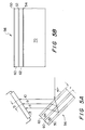
- Figure 8A shows an optical system employing the dual trichromatic beamsplitter with a prism.
- Figure 8B shows an isometric view of the dual trichromatic beamsplitter with a prism.
- FIG. 9 shows an alternate embodiment of the invention.
- Figure 10 is a test apparatus for the filters.
- Figure 11 is the spectral transmission of the filters in Figures 2A and 2B.
- Figure 12 is the output of the lamp tailored to the spectral transmission shown in Figure 11.
- each beamsplitter 2, 3 consists of a precisely ground and polished glass plate coated on one or both faces with a selected multilayer dielectric interference optical filter coating, 50, 52, 54 (hereinafter referred to as dichroic coating).
- dichroic coating At each dichroic coating 50, 52, 54, incident light is either reflected or transmitted according to wavelength with negligible absorption loss.
- the composition of the dichroic coatings 50, 52, 54 can be designed for accurate band pass filtration.
- Dichroic coatings are well known in the art of optics. Said coatings typically consist of 20 or more alternating high and low refractive index optical layers vacuum-deposited to an accumulative thickness of, typically, about 3 microns on a glass surface. The material composition and method of deposition can be designed for very accurate spectral bandpass filtration.
- a variety of dichroic filters, consisting of a single glass plate front surface coated with a dichroic coating, are commercially available from a variety of sources (e.g., Optical Coating Laboratory, Inc., located in Santa Rosa, California).
- Dichroic beamsplitter plates suitable for the invention are shown in Figures 2A and 2B.
- the beamsplitter plate 2 shown in Figure 2A is designed such that incident light striking its dichroic coating 50 at 45 degrees reflects blue light (spectral band approximately 400 - 500 nm.) while transmitting red light and green light.
- Beamsplitter 3 shown in Figure 2B is coated on both faces with dichroic coatings 52 and 54 such that incident light striking a first dichroic coating 52 at nominally 45 degrees reflects the red spectral band (e.g., 600 - 700 nm.) while transmitting the blue and green bands.
- the green light striking a second dichroic coating 54 and having an optical axis oriented nominally 45 degrees from the dichroic coating is reflected.
- the reflected green light is caused to pass back through the glass plate 62 and through the first dichroic coating 52 at a 45 degrees angle.
- the red and green components of the incident light are reflected at 90 degrees.
- the reflected red and green components are parallel and separated from each other by a distance determined by the glass plate 62 and dichroic coatings 52, 54, thickness and their refractive indexes.
- a trichromatic separation of an incident light beam can be achieved through a composite of beamsplitter plates 2 and 3, as shown in Figure 3.
- Each of the three spectrally-tailored dichroic coatings 50, 52, 54, are separated by a glass plate 60, 62 thickness.
- Incident light striking the first dichroic coating, and having an optical axes oriented 45 degrees from the dichroic coating is filtered such that the blue spectral band is reflected.
- the unreflected bands (red and green) are transmitted to a second dichroic coating 52 located between the glass plates 60 and 62.
- Coating 52 reflects the red spectral band.
- the remaining band, the green spectral band is reflected from the third dichroic coating 54.
- red, green, and blue components of the incident light beam are reflected at 90 degrees to the principal incident beam with a parallel spacial separation which is solely determined by the thickness of the glass plates 60, 62, and dichroic coatings 50, 52, and 54, and their refractive indexes.
- the order in which the reflected color bands have been presented is by example only. It is further obvious that a mirror coating could be substituted for the third dichroic coating 54, since only the third remaining color component reaches that coating interface.
- Photosensor 11 is preferrably a single chip, single package solid state device having three linear photosensor arrays, 12, 13 and 14, precisely aligned and spaced to coincide with the focused line images 8, 9 and 10, respectively, shown in Figures 3 and 5A.
- Such devices can be made using known technologies. For example, numerous photosensor array devices are now commercially available. Most prominent are photodiode arrays with charge-coupled shift registers (CCD photosensors).
- CCD photosensors charge-coupled shift registers
- Such single line CCD photodiode array devices are commercially available from Fairchild Semiconductor, located in Palo Alto, California, Toshiba, located in Japan, and other companies.
- the photosensor array devices have commercial resolutions ranging from 128 to over 5000 photoelements per line.
- the spacing between photoelements typically ranges from 10 to 62 microns.
- the design and manufacture of a photodiode array shown in Figure 4B uses known technologies to produce the three parallel photosensor arrays 12, 13 and 14.
- a distance “D” separates the photosensor arrays 12, 13, and 14.
- the distance “D” is related to the separation of the dichroic coatings 50, 52, and 54, and angle ⁇ of the photosensor 11.
- the distance between photosensors 12 and 13 does not have to be equal to the distance between photosensors 13 and 14.
- the three photosensor arrays 12, 13, and 14 have common clock inputs for synchronization.
- integrated circuit photolithography processes are capable of aligning and spacing the three linear photosensor arrays 12, 13 and 14 to submicron precision.
- the combined spacial precision of the described trichromatic beamsplitter 56 and three photosensor array detectors, 12, 13 and 14, allows accurate coincidence of the detected images with the single line image of the original.
- trichromatic beamsplitter 56 and photosensor 11 The preferred arrangement of trichromatic beamsplitter 56 and photosensor 11 is shown in an end view in Figure 5A. Due to the variations in path-length-through-glass between the three separated color components, beamsplitter 56 and photosensor 11 are mounted to have an inclusive angle less than 90 degrees, typically 80 degrees for nominal glass refractive index. Said angle is independent of the focal distance between the lens and photosensor. At said inclusive angle, the three separated color components will properly focus on their respective linear photosensor arrays 12, 13 and 14. The spacial separation of arrays 12, 13, and 14 is directly determined by the thickness of the glass plates 60, 62, dichroic coatings 50, 52, and 54, and their refractive indexes. (Standard lens formulas are used to calculate the angle and separation distances.) Trichromatic beamsplitter 56 and photosensor 11 are preferably assembled in a housing that maintains the desired angles and distances, and that consolidates the parts into a single package.
- a focused light beam transmitted through a glass plate at an angle of incidence other than 90 degrees is subject to oblique spherical aberration. This causes astigmatism. Increasing glass thickness and angle of incidence exacerbate the astigmatism.
- the red, blue, and green spectral components experience different degrees of degradation due to their different path lengths through the glass and the high angle of incidence (45 degrees). This compromises the focus and resolution of the color separation technique to the extent that the chromatic foci through the trichromatic beamsplitter occur beyond the depth of focus provided by the imaging lens.
- the thickness of the glass plates 60, 62 and dichroic coatings 50, 52, and 54, and the spacial separation of the three photosensor arrays 12, 13, and 14, in photosensor 11 are collectively minimized to render negligible the otherwise optical deficiencies and minimize cost.
- thin glass plates on the order of .1 to .2 millimeter
- a preferred method of beamsplitter manufacture will include a thick glass substrate 70, shown in Figure 5B, from which the trichromatic beamsplitter 56 is built up.
- the thick glass substrate 70 is ground flat, polished and coated with dichroic coating 54.
- glass plate 62 is bonded using an optical cement.
- glass plate 62 is then ground flat and polished to provide the desired thickness of coating, cement and glass as measured through the composite.
- glass plate 62 is coated with dichroic coating 52, then bonded to glass plate 60, at which point the surface of plate 60 is ground and polished to the desired thickness.
- dichroic coating 50 is deposited on the exposed surface of plate 60.
- An alternate embodiment utilizes a single pair of beamsplitter plates and a single prism.
- the incident light beam is aligned to impinge a first base side 30 of right-angle prism 1 at a normal angle and transmit therein to the hypotenuse face 32 of the prism 1 which the light beam impinges at 45 degrees.
- the composite beamsplitter 56 of Figure 3, consisting of beamsplitters 2 and 3, is attached thereto.
- a trichromatic separation of the red, green and blue spectral components of the incident light beam occurs as previously described.
- the three reflected component beams re-enter the prism 1 and are directed toward the second base side 34 of the prism.
- SQRT 2x optical axis spacial separation
- x is the thickness of the glass, optical cement and dichroic coating between two adjacent dichroic coatings.
- Trichromatic beamsplitter 56 with the prism 1 allows a 90 degree angle of incidence to glass and chromatic focusing to each sensor array 12, 13, and 14.
- the dual trichromatic beamsplitter with prism 59 shown in Figure 7A is adopted.
- the path-lengths-through-glass of the color-separated beams are made equal by the reciprocal arrangement of the trichromatic beamsplitters 56 and 58.
- the incident light beam is aligned to impinge the hypotenuse face 32 of right angle prism 1 at a normal angle and transmit therein to a first base side 30 of the prism 1 which the light beam impinges at 45 degrees.
- the composite beamsplitter 56 of Figure 3 is attached thereto.
- a trichromatic separation of the red, green and blue spectral components of the incident light beam occurs as previously described.
- the three reflected component beams reenter the prism 1 and are directed toward the second base side 34 of prism 1, each separated beam impinging the second base side 34 at 45 degrees incidence.
- a second composite beamsplitter 58 is attached to the second base side 34 of prism 1.
- the plates 60, 62 and the dichroic coatings 50, 52, and 54, in beamsplitters 56 and 58 are identical. However, the orientation of the composite beamsplitters 56 and 58, and their multilayer dielectric coatings 50, 52, and 54, on each base side 30, 34 of the prism 1 are reversed so that the path lengths of each component color beam entering and exiting the trichromatic prism beamsplitter 59 are identical. That is, a component color beam, such as blue, reflects off the dichroic coating 50 on plate 60 located on base side 30. Next, the blue component reflects off the dichroic coating 50 on plate 60 located adjacent to base side 34.
- a component color beam such as blue
- a red component color beam goes from middle filter 52 to middle filter 52, and the green component reflects off a backside filter 54 to a frontside filter 54 as shown in Figure 7A.
- Reflected beams from the trichromatic beamsplitter 58 adjacent to base side 34 are directed out of prism 1.
- the beams are perpendicular to the hypotenuse side 32 and parallel to the incident light beam.
- the thickness of the beamsplitter glass plates, 60, 62, and their dichroic coatings 50, 52, and 54, determine the separation of the reflected beams.
- the dual trichromatic beamsplitter 59 provides an equal path length through the glass for all color components. Also, the light enters and leaves the prism at a normal angle of incidence.
- trichromatic beamsplitter 59 would omit prism 1. Without the prism 1, incident light impinges the beamsplitter 56 and 58 at 45 degrees, creating astigmatic foci at the focal plane of photosensor 11. The degree of effect due to the astigmatism is functional to the depth of focus of the projection lens in the accompanying optical system and the spacial separation of the various dichroic coatings composing the trichromatic beamsplitter.
- the primary advantage of said alternative embodiment is the removal of glass in the optical path that a lens must otherwise be corrected for.
- an optical system employing the trichromatic beamsplitter 59 of Figure 7A is shown in Figures 8A and 8B.
- a similar optical system can be employed with the beamsplitters 56, 58, and prismless beamsplitter 59, in Figures 5A, 6 and 7A, respectively, or a beamsplitter that separates an incident light beam into more than three spectral bands through the compositing of multiple beamsplitter plates.
- a line image 7 of an original object is projected through an aperture 75 as shown in Figure 8A by a lens 6 through the hypotenuse face of prism 1 such that the optical axis of the incident beam is normal to said face.
- Aperture 75 is constructed to block images from far away adjacent object lines about the principal object line 7 which would otherwise allow multiple separated images to strike the photosensors.
- the incident beam is separated into its three color components as previously described.
- the blue, red and green components emerge from the prism 1 as line images 8, 9 and 10, respectively. Since the individual path lengths of the color component beams through the beamsplitter 58 are identical, the said line images 8, 9 and 10 reside on a single plane which is perpendicular to the hypotenuse face of prism 1.
- the spacial separation of the three line images 8, 9 and 10, is determined by the glass plate spacing of the six dichroic coatings, 50, 52, and 54, on the beamsplitter plates 60, 62.
- each line image, 8, 9 and 10 is electronically detected by one of three parallel spaced photosensors, 12, 13 and 14.
- FIG. 7B An assembly view of the described trichromatic beamsplitter 59 is shown in Figure 7B.
- the four beamsplitter plates 2, 3, 4, and 5 are oriented about prism 1 as shown and secured together with optical cement according to standard practice.
- Said optical cement is selected to have matching refractive index with the glass.
- Typical optical cements are polyester or acrylic based.
- glue line thickness preferrably micron to submicron glue films, to minimize random variation in the spacing of the dichroic coatings on the beamsplitter plates. This is typically accomplished by the application of heat and pressure to the composite structure during the adhesive process.
- the incurred separation of the three focus line images 8, 9 and 10 will be (SQRT 2)(2x).
- the separation of the dielectric optical filters, 50, 52 and 54 is dominated by the glass plate thickness (the filter 50, 52 and 54 thickness is typically 3 ⁇ m for standard dichroic coatings).
- the glass plate thickness principally determines the separation between image lines 8, 9 and 10. Variations in image lines 8, 9 and 10 separation are determined by variations in glass plate separation.
- the color component's path length through the trichromatic beamsplitter 59 is (2) 1/2 A + 2(2) 1/2 X where A is the dimension of a base side of prism 1, as shown in Figure 7A.
- A is the dimension of a base side of prism 1, as shown in Figure 7A.
- the line images 8, 9 and 10 and photosensor arrays 12, 13, and 14 preferrably have matched spacing.
- the spacing between photosensor arrays 12, 13, and 14 should be (SQRT 2)(2x) when the spacing between the dichroic coatings 50, 52, 54 is x in beamsplitter 59 as shown in Figure 7A.
- an array spacing of 1.0 mm requires a beamsplitter plate 60, 62, thickness of .35 mm. for beamsplitter 59.
- dichroic coatings 50, 52, and 54, applied to glass plates of such small thickness will cause a mild bowing of the glass plate.
- the profile view of Figure 8A has the appearance of a "projection" imaging apparatus. That is, a relatively long object line 7 is projected into smaller image lines 8, 9 and 10 via lens 6.
- the photoelements 80 shown in Figure 4B in the photosensor arrays 12, 13 and 14 must be proportionately smaller than the desired scanning resolution of the original.
- the advantages of such a "projection" type scanning device is the use of small photosensor arrays 12, 13 and 14.
- the present invention is not limited to "projection" optics and, in fact, is quite extensible into other product and application forms.
- the present trichromatic beamsplitter 59 and three linear array photosensor 11 can be packaged with a fiber array lens 15 to produce a "contact" type scan head 57, shown in Figure 9.
- "Contact" type scan heads 57 principally use lenses with unity magnification. As such, the lens and sensor can be compacted in close proximity to the original. (The scan head does not actually contact the original as the name would imply.)
- Fiber array lenses 15 are well known in the imaging field and are a product of Nippon Sheet Glass (Japan) under the name SelFoc Lens.
- the fiber array lenses 15 are available in small and long lengths such as page width.
- the fiber array lenses 15 are made of glass fibers of given length. Each fiber acts as an individual lens since chemical treatment varies the refractive index as a function of its radius. In this instance, the lens array 15 projects the line image of an original 7 through the trichromatic beamsplitter 59 to three linear array sensor 11.
- the length of the lens array 15, beamsplitter 59 (or other previously described beamsplitter embodiment) and photosensor 11, as it moves into the page in Figure 9, is determined by the application: relatively long lengths for page width scanning (e.g.
- the contact (unity magnification) type scan head 57 shown in Figure 9 requires proportionately less stringent tolerance on beamsplitter plates 2, 3, 4 and 5 thickness in comparison to the projection type scanner shown in Figures 8A and 8B.
- the contact scanner 57 must be proportionately longer as measured by the ratio of the lens magnifications, unless the scan head 57 is traversed across the original.
- a significant advantage of dichroic coatings 50, 52 and 54 over other filtration techniques is design versatility with respect to bandpass wavelengths and the slope and crossover characteristics of the band pass.
- Very sharp step function bandpass as well as controlled slope crossover with adjacent color bands is controlled by number of layers, material types, and coating layer thicknesses in a given filter.
- very clean bandpass discrimination can be achieved between red, green and blue or cyan, magenta and yellow.
- conventional organic dye filters as used in the prior art, are typically not as well-defined and usually have close band or multiple band filtration characteristics which ultimately prevents accurate color separation, usually due to undersaturation of a given detected trichromatic color.
- the teachings of the present invention have been principally applied to color document scanning. Scanned document images, in this instance, are displayed on a color monitor. The accuracy of the color separation is judged by the likeness of the displayed image colors to that of the original document. To obtain color fidelity, the color separation must match the spectral charateristics of the individual red, green and blue phosphorus in the monitor display screen. This was successfully achieved by using dichroic beamsplitters 16 and 17 and a phosphor-tailored fluorescent lamp 22 in a test apparatus, depicted in Figure 10. The test apparatus utilizes three single linear array CCD photosensors 18, 19 and 20 (Toshiba TCD 102C-1) with a 2048 element array.
- a fluorescent light source 22 illuminates the surface of an original document 21.
- a line image of the original 7 is projected onto a beamsplitter assembly, consisting of dichroic beamsplitters 16 and 17, by lens 6.
- Beamsplitters 16 and 17 are flat glass plates coated on one side with dichroic coatings 50 and 52, respectively.
- Beamsplitter 16 is designed to reflect blue light while transmitting red and green spectral bands. Said blue light is reflected to a first CCD linear-array photosensor 18, with beamsplitter 16 tilted at 45 degrees to the incident light beam.
- Beamsplitter 17 reflects red light to a second CCD photodiode array sensor 20.
- Said beamsplitter plates are Optical Coating Lab commercial blue and red 45 degree Dichroic Color Separation Filters.
- the green line image passing through both beamsplitter plates is captured by the third CCD photodiode array sensor 19.
- Beamsplitter plate 17 is also aligned at 45 degrees, as shown.
- the band pass characteristics of the collective beamsplitter assembly of Figure 10 is shown in Figure 11. Although the crossover wavelengths between color bands is clean and spectrally accurate for separation, the reflected bands do not share the spectral shape and balance of the output device's color palette.
- Output devices include monitors and hard copy devices. Spectral accuracy, in this case, is most easily provided by spectrally tailoring the light source 22. Fluorescent lamp phosphors can be blended to achieve a wide variety of spectra.
- the spectral bandpass characteristics of the dichroic coatings 50, 52 can be used to choose phosphors of the lamp 22 so that the color separation of the coatings 50, 52 will match the monitor's display phosphors.
Landscapes
- Physics & Mathematics (AREA)
- Spectroscopy & Molecular Physics (AREA)
- General Physics & Mathematics (AREA)
- Optics & Photonics (AREA)
- Engineering & Computer Science (AREA)
- Multimedia (AREA)
- Signal Processing (AREA)
- Color Television Image Signal Generators (AREA)
- Facsimile Scanning Arrangements (AREA)
- Optical Filters (AREA)
- Color Image Communication Systems (AREA)
- Facsimile Heads (AREA)
Claims (6)
- Un dispositif (59) servant à séparer spatialement et spectralement un faisceau optique d'entrée en une série de faisceaux optiques (8, 9, 10) d'une manière telle que chaque faisceau optique de ladite série possède une plage spectrale prédéterminée et d'une manière telle que les longueurs des trajets optiques des axes optiques de ladite série de faisceaux optiques soient sensiblement égaux entre un premier plan sensiblement normal à ladite série des faisceaux optiques et un deuxième plan sensiblement normal audit faisceau optique d'entrée,
ledit dispositif optique comprenant:
un premier moyen de filtre composite (56) disposé selon un premier angle prédéterminé d'incidence par rapport audit faisceau optique d'entrée afin de séparer spatialement et spectralement ledit faisceau optique d'entrée en ladite série de faisceaux optiques (8, 9, 10) d'une manière telle que chaque faisceau optique de la série présente une plage spectrale prédéterminée et soit dirigé sensiblement dans la même direction;
un deuxième moyen de filtre composite (58) disposé selon un deuxième angle prédéterminé d'incidence par rapport à ladite série de faisceaux optiques (8, 9, 10) afin d'égaliser lesdites longueurs des trajets optiques desdits axes optiques de chacun des faisceaux optiques de ladite série entre ledit premier et ledit deuxième plans;
lesdits premier et deuxième moyens de filtres composites (56, 58) comprenant chacun au moins une entretoise optique (60) constituée par une première couche transparente d'une épaisseur prédéterminée; une deuxième couche (50) disposée sur un côté de l'entretoise optique (60) afin de réfléchir une lumière située à l'intérieur d'une première plage spectrale optique et de transmettre une lumière située à l'extérieur de ladite première plage spectrale prédéterminée, et une troisième couche (52) disposée sur le deuxième côté de l'entretoise optique (60) pour réfléchir au moins une deuxième plage spectrale prédéterminée de lumière située à l'extérieur de ladite première plage spectrale prédéterminée, la séquence de réflexion de plage spectrale dans le deuxième moyen de filtre composite (58) étant inversée par rapport au premier moyen de filtre composite (56). - Dispositif selon la revendication 1 dans lequel la source dudit faisceau optique d'entrée comprend une source linéaire (7).
- Le dispositif selon la revendication 1 ou 2 dans lequel ledit premier angle prédéterminé d'incidence et ledit deuxième angle prédéterminé d'incidence sont sensiblement égaux.
- Le dispositif optique selon l'une des revendications 1 à 3 dans lequel:
ladite deuxième couche comprend une première couche dichroïque (50);
ladite troisième couche comprend une deuxième couche dichroïque (52) disposée sur le deuxième côté de ladite entretoise optique (60) afin de réfléchir une lumière située dans une deuxième plage spectrale prédéterminée et de transmettre une lumière située à l'extérieur de ladite deuxième plage spectrale prédéterminée; et
lesdits premier et deuxième moyens de filtres composites comprennent en outre
un revêtement réflecteur (54) disposé à une distance prédéterminée de ladite entretoise optique (60) et essentiellement parallèle à celle-ci, afin de réfléchir une lumière transmise par ladite première couche dichroïque (60) et ladite deuxième dichroïque (52). - Le dispositif optique selon la revendication 4 dans lequel ladite épaisseur prédéterminée de ladite entretoise optique (60) est essentiellement égale à ladite distance prédéterminée entre ledit revêtement réflecteur (54) et ladite entretoise optique (60).
- Le dispositif optique selon l'une quelconque des revendications 1 à 5 dans lequel chacun desdits premier et deuxième moyens de filtres composites (56, 58) est attaché à une face différente d'un prisme (1).
Applications Claiming Priority (2)
| Application Number | Priority Date | Filing Date | Title |
|---|---|---|---|
| US06/847,382 US4709144A (en) | 1986-04-02 | 1986-04-02 | Color imager utilizing novel trichromatic beamsplitter and photosensor |
| US847382 | 1986-04-02 |
Publications (3)
| Publication Number | Publication Date |
|---|---|
| EP0240000A2 EP0240000A2 (fr) | 1987-10-07 |
| EP0240000A3 EP0240000A3 (en) | 1989-08-30 |
| EP0240000B1 true EP0240000B1 (fr) | 1994-02-02 |
Family
ID=25300486
Family Applications (1)
| Application Number | Title | Priority Date | Filing Date |
|---|---|---|---|
| EP87104776A Expired - Lifetime EP0240000B1 (fr) | 1986-04-02 | 1987-03-31 | Appareil pour la séparation d'ondes électromagnétiques |
Country Status (4)
| Country | Link |
|---|---|
| US (2) | US4709144A (fr) |
| EP (1) | EP0240000B1 (fr) |
| JP (1) | JP2552856B2 (fr) |
| DE (1) | DE3788969T2 (fr) |
Families Citing this family (104)
| Publication number | Priority date | Publication date | Assignee | Title |
|---|---|---|---|---|
| US5020118A (en) * | 1984-06-13 | 1991-05-28 | Canon Kabushiki Kaisha | Image reading apparatus |
| US4870268A (en) * | 1986-04-02 | 1989-09-26 | Hewlett-Packard Company | Color combiner and separator and implementations |
| US5592309A (en) * | 1986-05-02 | 1997-01-07 | Scitex Corporation Ltd. | Multiple lens separation scanner |
| US5237446A (en) * | 1987-04-30 | 1993-08-17 | Olympus Optical Co., Ltd. | Optical low-pass filter |
| EP0325361B1 (fr) * | 1988-01-19 | 1995-06-28 | Hewlett-Packard Company | Système de projection de couleurs |
| JPH0218518A (ja) * | 1988-07-07 | 1990-01-22 | Think Lab Kk | 光ビーム分割器 |
| US5187358A (en) * | 1989-02-15 | 1993-02-16 | Canon Kabushiki Kaisha | Image reading device having a telecentric optical system and a blazed diffraction grating |
| JPH07121047B2 (ja) * | 1989-02-15 | 1995-12-20 | キヤノン株式会社 | カラー画像読取り装置 |
| US5045932A (en) * | 1989-06-29 | 1991-09-03 | Eastman Kodak Company | Method and apparatus for generating a high definition electronic signal from a line scan of a color original |
| JPH0347474A (ja) * | 1989-07-12 | 1991-02-28 | Mitsubishi Electric Corp | 配電器内蔵クランク角センサ |
| US4926041A (en) * | 1989-07-20 | 1990-05-15 | Hewlett-Packard Company | Optical scanner |
| US4959541A (en) * | 1989-08-03 | 1990-09-25 | Hewlett-Packard Company | Method for determining aperture shape |
| EP0416927A3 (en) * | 1989-09-08 | 1992-01-02 | Konica Corporation | Image reader and color separation device |
| JP2528371B2 (ja) * | 1989-12-29 | 1996-08-28 | ホーヤ株式会社 | 多波長ビ―ムスプリッタ装置 |
| US5019703A (en) * | 1990-01-25 | 1991-05-28 | Hewlett-Packard Company | Optical scanner with mirror mounted occluding aperture or filter |
| JPH03226067A (ja) * | 1990-01-30 | 1991-10-07 | Canon Inc | カラー画像読取り装置 |
| US5144498A (en) * | 1990-02-14 | 1992-09-01 | Hewlett-Packard Company | Variable wavelength light filter and sensor system |
| US5032004A (en) * | 1990-03-23 | 1991-07-16 | Hewlett-Packard Company | Beam splitter apparatus with adjustable image focus and registration |
| US5040872A (en) * | 1990-03-23 | 1991-08-20 | Hewlett-Packard Company | Beam splitter/combiner with path length compensator |
| JP2622185B2 (ja) * | 1990-06-28 | 1997-06-18 | シャープ株式会社 | カラー液晶表示装置 |
| JPH04212102A (ja) * | 1990-07-26 | 1992-08-03 | Canon Inc | ダイクロイックミラーおよび該ミラーを用いた投写型表示装置 |
| US5099359A (en) * | 1990-09-11 | 1992-03-24 | Eastman Kodak Company | Composite optical interference filter for use in film scanner system |
| JPH04163401A (ja) * | 1990-10-26 | 1992-06-09 | Canon Inc | カラー画像読取装置 |
| US5285271A (en) * | 1991-05-14 | 1994-02-08 | Hewlett-Packard Company | Digital color matrixing circuit |
| DE69218402T2 (de) * | 1992-04-15 | 1997-10-16 | Hewlett Packard Co | Farbbildaufnahmevorrichtung und -verfahren |
| US5410347A (en) * | 1992-08-19 | 1995-04-25 | Hewlett-Packard Company | Color optical scanner with image registration holding assembly |
| US5339107A (en) * | 1992-08-19 | 1994-08-16 | Hewlett-Packard Company | Color optical scanner with rotating color filter assembly |
| JPH06148559A (ja) * | 1992-11-13 | 1994-05-27 | Canon Inc | カラー画像読取装置 |
| JPH06222212A (ja) * | 1992-12-03 | 1994-08-12 | Matsushita Electric Ind Co Ltd | 偏波面回転光学装置及び偏光変換光学装置及び投写型表示装置 |
| US5438414A (en) * | 1993-01-22 | 1995-08-01 | The Johns Hopkins University | Integrated dual imaging detector |
| US5306908A (en) * | 1993-03-15 | 1994-04-26 | Hewlett-Packard Company | Manually operated hand-held optical scanner with tactile speed control assembly |
| US5381020A (en) * | 1993-03-31 | 1995-01-10 | Hewlett-Packard Company | Hand-held optical scanner with onboard battery recharging assembly |
| US5336878A (en) * | 1993-05-10 | 1994-08-09 | Hewlett-Packard Company | Variable speed single pass color optical scanner |
| US5406066A (en) * | 1993-07-06 | 1995-04-11 | Hewlett-Packard Company | Method and apparatus for correcting color registration error |
| US5459611A (en) * | 1993-08-18 | 1995-10-17 | Hewlett-Packard Company | Beam splitter/combiner with path length compensator and method for making the same |
| JPH07234501A (ja) * | 1994-02-22 | 1995-09-05 | Matsushita Electric Ind Co Ltd | 色分解装置およびカラー画像読取装置 |
| US5552597A (en) * | 1994-07-06 | 1996-09-03 | Hewlett-Packard Company | Hand-held scanner having adjustable light path |
| US5586212A (en) * | 1994-07-06 | 1996-12-17 | Hewlett-Packard | Optical wave guide for hand-held scanner |
| US5541771A (en) * | 1994-08-22 | 1996-07-30 | Hewlett-Packard Company | Beam splitter for use in a color imaging assembly |
| US5483053A (en) * | 1994-09-27 | 1996-01-09 | Hewlett-Packard Company | Variable resolution color image scanner having an exposure delay between successive linear photosensors detecting different colors |
| FI97264C (fi) * | 1994-10-28 | 1996-11-11 | Tvi Temet Vision Ind Oy | Menetelmä valoilmaisinrivin asemoimiseksi ja valojako- ja ilmaisinrakenne viivakameraa varten |
| US5523562A (en) * | 1994-10-31 | 1996-06-04 | Hewlett-Packard Company | Optical scanner having enhanced depth of illumination |
| JP3240870B2 (ja) * | 1995-02-09 | 2001-12-25 | キヤノン株式会社 | カラー画像読取装置 |
| DE19604795C2 (de) * | 1995-03-14 | 2001-05-17 | Hewlett Packard Co | Farbtrennung unter Verwendung einer Mehrpunkt-Schmalbandbeleuchtung von Lichtquellen mit N Farben |
| US5646394A (en) * | 1995-03-16 | 1997-07-08 | Hewlett-Packard Company | Imaging device with beam steering capability |
| JP3629068B2 (ja) * | 1995-07-04 | 2005-03-16 | ペンタックス株式会社 | 色分解光学装置 |
| KR970009185A (ko) * | 1995-07-31 | 1997-02-24 | 김광호 | 색분해장치 |
| US5805311A (en) * | 1995-08-18 | 1998-09-08 | Hewlett-Packard Company | Color optical scanner with single linear array |
| US5723859A (en) * | 1996-01-29 | 1998-03-03 | Hewlett-Packard Company | Line contact hand-held scanning device and method having a light path substantially perpendicular to the orientation of the object at a line portion |
| US5777321A (en) * | 1996-01-29 | 1998-07-07 | Hewlett-Packard Company | Scanning device with non-contact optical components |
| US6404550B1 (en) | 1996-07-25 | 2002-06-11 | Seiko Epson Corporation | Optical element suitable for projection display apparatus |
| GB2317021A (en) * | 1996-08-28 | 1998-03-11 | Seos Displays Ltd | An optical device |
| US5808293A (en) * | 1996-08-28 | 1998-09-15 | Hewlett-Packard Company | Photo detector with an integrated mirror and a method of making the same |
| US5895913A (en) * | 1997-01-09 | 1999-04-20 | Hewlett-Packard Company | Method and apparatus for moving a carriage to a home position |
| US5753908A (en) * | 1997-01-09 | 1998-05-19 | Hewlett-Packard Company | Photoelectric imaging device photosensor array alignment apparatus and method |
| US5920407A (en) * | 1997-01-09 | 1999-07-06 | Hewlett-Packard Company | Method and apparatus for applying tonal correction to image data |
| GB2321532A (en) * | 1997-01-22 | 1998-07-29 | Sharp Kk | Multi-colour reflector device and display |
| US6152546A (en) * | 1997-02-12 | 2000-11-28 | General Electric Company | Traction vehicle/wheel slip and slide control |
| US5995243A (en) * | 1997-06-18 | 1999-11-30 | Hewlett-Packard Company | Illumination system with white level calibration for hand-held scanner |
| US6064496A (en) * | 1997-06-18 | 2000-05-16 | Hewlett-Packard Company | Scanning device with floating window member |
| US6639203B1 (en) | 1997-07-02 | 2003-10-28 | Hewlett-Packard Development Company, L.P. | Catadioptric lens system for a scanning device |
| US6040572A (en) * | 1998-05-21 | 2000-03-21 | Hewlett-Packard Company | Notebook styled scanner |
| JP3555451B2 (ja) * | 1998-06-22 | 2004-08-18 | ミノルタ株式会社 | 偏光変換ダイクロイックミラーと液晶プロジェクター |
| US6147343A (en) * | 1998-07-23 | 2000-11-14 | Hewlett-Packard Company | Photoelectric imaging method and apparatus |
| JP4246818B2 (ja) | 1998-08-03 | 2009-04-02 | パナソニック株式会社 | 画像入力装置及び画像入力方法 |
| USD412496S (en) * | 1998-09-03 | 1999-08-03 | Hewlett-Packard Company | Notebook scanner |
| EP1014693A3 (fr) * | 1998-12-23 | 2000-09-06 | Hewlett-Packard Company | Séparation des couleurs pour l'analyse d'images en plus de trois couleurs |
| US6265705B1 (en) | 1999-04-13 | 2001-07-24 | Hewlett-Packard Company | Alignment apparatus and method for an imaging system |
| US6118598A (en) * | 1999-04-13 | 2000-09-12 | Hewlett-Packard Company | Method and apparatus for setting focus in an imaging device |
| US6614471B1 (en) | 1999-05-10 | 2003-09-02 | Banctec, Inc. | Luminance correction for color scanning using a measured and derived luminance value |
| US6341040B1 (en) * | 1999-06-08 | 2002-01-22 | Jds Uniphase Corporation | Multi-plate comb filter and applications therefor |
| US6278101B1 (en) | 1999-08-05 | 2001-08-21 | Hewlett Packard Company | Method for increasing the native resolution of an image sensor |
| US6486459B1 (en) * | 1999-08-30 | 2002-11-26 | Xerox Corporation | Color beam splitter using air-spaced prisms |
| US7554586B1 (en) | 1999-10-20 | 2009-06-30 | Rochester Institute Of Technology | System and method for scene image acquisition and spectral estimation using a wide-band multi-channel image capture |
| US8536513B2 (en) | 2001-06-20 | 2013-09-17 | Hewlett-Packard Development Company, L.P. | Space-saving flatbed scanner |
| JP2004144678A (ja) * | 2002-10-25 | 2004-05-20 | Arkray Inc | 光学ユニット、光センサ、マルチチャンネル光検出装置及び光学ユニットの製造方法 |
| JP4837279B2 (ja) * | 2004-04-05 | 2011-12-14 | オリンパス株式会社 | 落射顕微鏡および蛍光フィルターセット |
| CN100370308C (zh) * | 2004-06-30 | 2008-02-20 | 北京万方同辉科技有限公司 | 一种分色镜堆 |
| CN100370307C (zh) * | 2004-06-30 | 2008-02-20 | 北京万方同辉科技有限公司 | 一种基于分色镜堆的调光方法及调光装置 |
| ITMI20050590A1 (it) * | 2005-04-08 | 2006-10-09 | Antonini Andrea | Sistema fotovoltaico a concentrrazione di radiazione basato su selezione spettrale |
| US7741557B2 (en) * | 2005-12-19 | 2010-06-22 | Corning Incorporated | Apparatus for obtaining radiant energy |
| US20070158535A1 (en) * | 2006-01-12 | 2007-07-12 | Cory Watkins | Color imaging using monochrome imagers |
| JP4836625B2 (ja) * | 2006-03-24 | 2011-12-14 | パナソニック株式会社 | 固体撮像素子 |
| US7483213B2 (en) * | 2006-03-24 | 2009-01-27 | Omnitech Partners | Image combining viewer |
| US8107167B2 (en) * | 2009-05-04 | 2012-01-31 | The Regents Of The University Of Michigan | Spatial-dispersion-free spectral combining of pulsed high peak power fiber laser beams |
| US8238029B2 (en) * | 2009-11-13 | 2012-08-07 | Microvision, Inc. | Dichroic filter laser beam combining |
| US8376551B2 (en) * | 2010-02-25 | 2013-02-19 | Corning Incorporated | Illumination system for laser projection |
| US8622549B2 (en) * | 2011-06-29 | 2014-01-07 | Microvision, Inc. | Beam combiner for a scanned beam display |
| US9375172B2 (en) | 2011-11-07 | 2016-06-28 | Corning Incorporated | Apparatus for substance detection |
| US9258468B2 (en) | 2012-02-15 | 2016-02-09 | Fluxdata, Inc. | Method and apparatus for separate spectral imaging and sensing |
| EP2876482A4 (fr) * | 2012-07-19 | 2016-04-13 | Nikon Corp | Élément optique, dispositif optique, dispositif de mesure et dispositif de tri |
| US9638988B2 (en) * | 2013-12-12 | 2017-05-02 | Corning Incorporated | Light multiplexer with color combining element |
| EP3108222B1 (fr) * | 2014-02-17 | 2022-03-30 | Eaton Intelligent Power Limited | Capteur d'oxygene comprenant une fibre optique ayant un diametre large et une pointe revetue |
| US9655519B2 (en) | 2014-03-21 | 2017-05-23 | Hypermed Imaging, Inc. | Systems and methods for performing an imaging test under constrained conditions |
| AU2015230939B2 (en) | 2014-03-21 | 2019-05-02 | Hypermed Imaging, Inc. | Compact light sensor |
| US10459230B2 (en) * | 2016-02-02 | 2019-10-29 | Disney Enterprises, Inc. | Compact augmented reality / virtual reality display |
| WO2017201093A1 (fr) | 2016-05-17 | 2017-11-23 | Hypermed Imaging, Inc. | Imageur hyperspectral couplé à une poursuite de molécules indicatrices |
| CN106094224B (zh) * | 2016-08-04 | 2019-07-12 | 上海凯利泰医疗科技股份有限公司 | 一种转折分光单元及内窥镜光学成像系统、成像方法 |
| US10317344B2 (en) * | 2016-09-07 | 2019-06-11 | Kla-Tencor Corporation | Speed enhancement of chromatic confocal metrology |
| US10641939B2 (en) * | 2017-05-19 | 2020-05-05 | Ayar Labs, Inc. | Beam turning assembly with polarization splitter |
| US12066609B2 (en) * | 2018-06-27 | 2024-08-20 | The Charles Stark Draper Laboratory, Inc. | Multiple effective focal length (EFL) optical system |
| TWI749814B (zh) * | 2020-10-16 | 2021-12-11 | 虹光精密工業股份有限公司 | 多模式掃描裝置 |
| CN112987149B (zh) * | 2021-04-21 | 2023-01-20 | 广州立景创新科技有限公司 | 复合棱镜模块以及图像获取模块 |
| LT7041B (lt) * | 2022-05-20 | 2024-01-10 | Valstybinis mokslinių tyrimų institutas Fizinių ir technologijos mokslų centras | Detektavimo įrenginys, sistema ir būdas, skirti optinio pluošto kritimo kampui nustatyti |
Family Cites Families (17)
| Publication number | Priority date | Publication date | Assignee | Title |
|---|---|---|---|---|
| US2392978A (en) * | 1942-07-27 | 1946-01-15 | Rca Corp | Light divider |
| US2749792A (en) * | 1951-11-05 | 1956-06-12 | Technicolor Motion Picture | Light dividing system |
| US3498693A (en) * | 1967-01-24 | 1970-03-03 | Zenith Radio Corp | Radiation translating devices |
| US3659918A (en) * | 1970-03-24 | 1972-05-02 | Philips Corp | Color separating prism system |
| US3753822A (en) * | 1971-03-25 | 1973-08-21 | Laser Optics Inc | Method of making a multi-layer optical isolation |
| DE2515501C2 (de) * | 1975-04-09 | 1982-09-09 | Agfa-Gevaert Ag, 5090 Leverkusen | Verfahren zum zeilenweisen Abtasten einer kontinuierlich bewegten Vorlage |
| JPS53118645U (fr) * | 1977-02-28 | 1978-09-20 | ||
| US4185894A (en) * | 1978-03-13 | 1980-01-29 | Hughes Aircraft Company | Dielectric reflector for selective wavelength reflection |
| JPS54158247A (en) * | 1978-06-02 | 1979-12-13 | Nippon Telegr & Teleph Corp <Ntt> | Optical wave divider |
| US4408825A (en) * | 1980-11-10 | 1983-10-11 | Acton Research Corporation | Vacuum ultraviolet reflectance filter |
| JPS58180524U (ja) * | 1982-05-28 | 1983-12-02 | 三菱電機株式会社 | 組合せプリズム |
| JPS5918922A (ja) * | 1982-07-23 | 1984-01-31 | Mitsubishi Electric Corp | 光分波器 |
| JPS601119U (ja) * | 1983-06-15 | 1985-01-07 | 日立電線株式会社 | 光分波器 |
| US4555163A (en) * | 1983-09-22 | 1985-11-26 | Rca Corporation | Complementary color splitting filters used in a color camera |
| GB2153546A (en) * | 1984-02-02 | 1985-08-21 | Pilkington Perkin Elmer Ltd | Optical filtering devices |
| DE3413703A1 (de) * | 1984-04-12 | 1985-10-24 | Standard Elektrik Lorenz Ag, 7000 Stuttgart | Optischer multiplexer/demultiplexer |
| JPS61198102A (ja) * | 1985-02-27 | 1986-09-02 | Furukawa Electric Co Ltd:The | フイルタ付き光導波路の製造方法 |
-
1986
- 1986-04-02 US US06/847,382 patent/US4709144A/en not_active Expired - Lifetime
-
1987
- 1987-03-31 DE DE3788969T patent/DE3788969T2/de not_active Expired - Lifetime
- 1987-03-31 EP EP87104776A patent/EP0240000B1/fr not_active Expired - Lifetime
- 1987-04-02 JP JP62082754A patent/JP2552856B2/ja not_active Expired - Lifetime
- 1987-11-23 US US07/124,225 patent/US4806750A/en not_active Expired - Lifetime
Also Published As
| Publication number | Publication date |
|---|---|
| JPS62234106A (ja) | 1987-10-14 |
| EP0240000A3 (en) | 1989-08-30 |
| DE3788969D1 (de) | 1994-03-17 |
| JP2552856B2 (ja) | 1996-11-13 |
| US4709144A (en) | 1987-11-24 |
| US4806750A (en) | 1989-02-21 |
| EP0240000A2 (fr) | 1987-10-07 |
| DE3788969T2 (de) | 1994-08-18 |
Similar Documents
| Publication | Publication Date | Title |
|---|---|---|
| EP0240000B1 (fr) | Appareil pour la séparation d'ondes électromagnétiques | |
| US4870268A (en) | Color combiner and separator and implementations | |
| EP0325363B1 (fr) | Dispositif de condition spectrale | |
| US7394543B2 (en) | Spectral selection and image conveyance using micro filters and optical fibers | |
| EP0447644A1 (fr) | Décompositeur/compositeur de faisceau avec compensateur de la longeur de trajet optique | |
| US5044727A (en) | Beam splitter/combiner apparatus | |
| US4555163A (en) | Complementary color splitting filters used in a color camera | |
| US6698893B2 (en) | Optical device suitable for separating and synthesizing light | |
| EP0565776B1 (fr) | Dispositif et méthode de capteur d'image couleur | |
| AU627134B2 (en) | A beam splitter for color imaging apparatus | |
| WO2022111459A1 (fr) | Structure de puce, ensemble caméra et dispositif électronique | |
| JPH07143284A (ja) | カラー画像読み取り装置及び色分解フィルタ基板の製造方法 | |
| JPS6328551B2 (fr) | ||
| JPH0870371A (ja) | カラー画像読取装置 | |
| JPH0396063A (ja) | 画像読取装置 | |
| JPS62257264A (ja) | カラ−画像読取装置 | |
| JPH06326833A (ja) | カラー画像読取装置 | |
| JPS6234456A (ja) | カラ−イメ−ジセンサ | |
| JPH04196965A (ja) | カラー画像読取装置 | |
| JPH07236028A (ja) | カラー画像読取装置 | |
| JPH03172066A (ja) | カラー画像読取り装置 | |
| JPH03135509A (ja) | 等倍結像素子 | |
| JPS61293060A (ja) | カラ−原稿読取り装置 | |
| JPS63261965A (ja) | 固体撮像部品 |
Legal Events
| Date | Code | Title | Description |
|---|---|---|---|
| PUAI | Public reference made under article 153(3) epc to a published international application that has entered the european phase |
Free format text: ORIGINAL CODE: 0009012 |
|
| AK | Designated contracting states |
Kind code of ref document: A2 Designated state(s): DE FR GB |
|
| PUAL | Search report despatched |
Free format text: ORIGINAL CODE: 0009013 |
|
| AK | Designated contracting states |
Kind code of ref document: A3 Designated state(s): DE FR GB |
|
| 17P | Request for examination filed |
Effective date: 19891018 |
|
| RIN1 | Information on inventor provided before grant (corrected) |
Inventor name: NEUMANN, HANS D. Inventor name: VINCENT, KENT D. |
|
| 17Q | First examination report despatched |
Effective date: 19911008 |
|
| GRAA | (expected) grant |
Free format text: ORIGINAL CODE: 0009210 |
|
| AK | Designated contracting states |
Kind code of ref document: B1 Designated state(s): DE FR GB |
|
| REF | Corresponds to: |
Ref document number: 3788969 Country of ref document: DE Date of ref document: 19940317 |
|
| ET | Fr: translation filed | ||
| PLBE | No opposition filed within time limit |
Free format text: ORIGINAL CODE: 0009261 |
|
| STAA | Information on the status of an ep patent application or granted ep patent |
Free format text: STATUS: NO OPPOSITION FILED WITHIN TIME LIMIT |
|
| 26N | No opposition filed | ||
| REG | Reference to a national code |
Ref country code: GB Ref legal event code: 732E |
|
| REG | Reference to a national code |
Ref country code: FR Ref legal event code: TP |
|
| REG | Reference to a national code |
Ref country code: GB Ref legal event code: IF02 |
|
| PGFP | Annual fee paid to national office [announced via postgrant information from national office to epo] |
Ref country code: FR Payment date: 20060317 Year of fee payment: 20 |
|
| PGFP | Annual fee paid to national office [announced via postgrant information from national office to epo] |
Ref country code: GB Payment date: 20060329 Year of fee payment: 20 |
|
| PGFP | Annual fee paid to national office [announced via postgrant information from national office to epo] |
Ref country code: DE Payment date: 20060502 Year of fee payment: 20 |
|
| PG25 | Lapsed in a contracting state [announced via postgrant information from national office to epo] |
Ref country code: GB Free format text: LAPSE BECAUSE OF EXPIRATION OF PROTECTION Effective date: 20070330 |
|
| REG | Reference to a national code |
Ref country code: GB Ref legal event code: PE20 |