EP0239114B1 - Schwingförderer nach dem Gleitförderprinzip - Google Patents
Schwingförderer nach dem Gleitförderprinzip Download PDFInfo
- Publication number
- EP0239114B1 EP0239114B1 EP87104516A EP87104516A EP0239114B1 EP 0239114 B1 EP0239114 B1 EP 0239114B1 EP 87104516 A EP87104516 A EP 87104516A EP 87104516 A EP87104516 A EP 87104516A EP 0239114 B1 EP0239114 B1 EP 0239114B1
- Authority
- EP
- European Patent Office
- Prior art keywords
- movement
- leaf springs
- counterweight
- conveyor
- trough
- Prior art date
- Legal status (The legal status is an assumption and is not a legal conclusion. Google has not performed a legal analysis and makes no representation as to the accuracy of the status listed.)
- Expired - Lifetime
Links
- 230000001133 acceleration Effects 0.000 claims abstract description 9
- 230000001419 dependent effect Effects 0.000 claims abstract description 9
- 230000008878 coupling Effects 0.000 claims abstract description 7
- 238000010168 coupling process Methods 0.000 claims abstract description 7
- 238000005859 coupling reaction Methods 0.000 claims abstract description 7
- 239000006096 absorbing agent Substances 0.000 claims abstract 3
- 230000003534 oscillatory effect Effects 0.000 claims abstract 2
- 230000005284 excitation Effects 0.000 claims description 9
- 230000035939 shock Effects 0.000 claims 1
- 230000003068 static effect Effects 0.000 description 5
- 230000010355 oscillation Effects 0.000 description 4
- 230000015572 biosynthetic process Effects 0.000 description 2
- 238000013016 damping Methods 0.000 description 2
- 238000005516 engineering process Methods 0.000 description 2
- 238000011835 investigation Methods 0.000 description 2
- 239000002245 particle Substances 0.000 description 2
- 230000001788 irregular Effects 0.000 description 1
- 238000012423 maintenance Methods 0.000 description 1
- 238000012544 monitoring process Methods 0.000 description 1
- 239000007787 solid Substances 0.000 description 1
- 125000006850 spacer group Chemical group 0.000 description 1
Images
Classifications
-
- B—PERFORMING OPERATIONS; TRANSPORTING
- B65—CONVEYING; PACKING; STORING; HANDLING THIN OR FILAMENTARY MATERIAL
- B65G—TRANSPORT OR STORAGE DEVICES, e.g. CONVEYORS FOR LOADING OR TIPPING, SHOP CONVEYOR SYSTEMS OR PNEUMATIC TUBE CONVEYORS
- B65G27/00—Jigging conveyors
- B65G27/08—Supports or mountings for load-carriers, e.g. framework, bases, spring arrangements
Definitions
- the invention relates to a vibratory conveyor according to the sliding conveyor principle with a drive oscillating movement for a conveyor trough, which has a coupling to a counterweight, through which the movement of the conveyor trough in the conveying direction is connected with a vertical upward movement and the return movement with a vertical downward movement, the vertical movement Acceleration generated by the upward movement does not lead to a lifting of the parts to be conveyed from the conveyor trough, with a drive for the conveyor trough mounted on the counter mass, which accelerates in the conveying direction at an angle of incidence ( T ) of 45 to 70 ° to the trough bottom with a frequency of clearly generated under 25 Hz and a movement amplitude of 5 to 40 mm.
- T angle of incidence
- Vibratory conveyors in the form of vibratory conveying pots have been known for many years and are used industrially in a variety of ways to feed mass parts.
- the vibrating conveyor pots have on their outer circumference a coiled path on which the mass parts are separated and, if necessary, sorted according to their position, so that they can be removed one after the other in the desired orientation at the upper end of the coiled path.
- the vibrating bowls which have been used in principle unchanged for many years, have a drive which consists of inclined leaf springs which are aligned approximately tangentially on the outer circumferential circle of the vibrating bowl and connect the lower counterweight to the useful mass formed by the rocker bowl. The leaf springs are at an angle of 70 to 80 ° to the horizontal.
- a centrally located excitation magnet originally used has proven to be unsuitable because of its very low efficiency.
- excitation magnets provided on the outer circumferential circle of the feed pot, which are aligned approximately perpendicular to the leaf spring.
- the mass parts are imprinted with a harmonic excitation, a micro-throwing motion with a discharge angle of 10 to 20 ° .
- the micro-throws lead to a not inconsiderable mechanical load on the mass parts, generate considerable noise and cause very irregular conveyance, which depends on a large number of unmanageable parameters.
- the vibratory bowls therefore require constant monitoring and maintenance.
- DE-OS 3 331 050 has attempted to replace the micro-throwing movement with a pure sliding movement.
- a purely horizontal acceleration is exerted on the conveyor trough, which leads to a higher speed than the return movement caused by springs (non-harmonic excitation).
- the parts which are strongly accelerated in the forward direction, slide a little further when braking. Since the restoring movement takes place at a lower speed, the parts are conveyed back with the restoring movement by the amount of the restoring movement, but they do not slide since the static friction is not overcome due to the low speed.
- This funding principle poses considerable problems in terms of control technology and is very critical in its setting, since during the forward movement itself the static friction must not be exceeded, but only when braking, while the braking must also be maintained when braking the backward movement.
- the application of this principle presupposes extraordinarily well-defined parts, which must already be predetermined in their position if they are not uniformly designed on all sides. A practical application of this principle therefore seems possible at most for special cases.
- a vibratory conveyor pot in which a hyperbolic elastic sleeve, which consists of hyperbolic spring elements, is connected on the one hand to a countermass and on the other hand forms a flange, which in turn is connected to the bottom of the feed pot via a spring connection is.
- a pneumatic damper assembly is provided between the flange and the bottom. The vibration excitation takes place between the stationary one Counter mass and the upper flange of the elastic sleeve.
- the arrangement in which the upper flange forms an oscillating intermediate mass serves to subject the oscillating pot to an oscillation in which the movement excitations in the vertical and in the angular path direction occur out of phase, so that each point of the oscillating cup moves on an elliptical path.
- the implementation of a sliding promotion is not disclosed.
- the invention has for its object to make the advantages inherent in the sliding conveyor principle achievable with an industrially feasible vibratory conveyor.
- the arrangement of the speed-dependent dampers according to the invention has no model in vibratory conveyor technology.
- the known vibrating bowls working at higher frequencies have not been equipped with dampers.
- the invention is based on extensive investigations, which have shown that the defined sliding movement can only be realized before an adequate damping system is present.
- the speed-dependent dampers are provided according to the invention.
- the use of the speed-dependent damper is particularly advantageous if the drive is formed by leaf springs known per se with one or more oscillating magnets, the leaf springs being arranged perpendicular to the starting angle.
- the vibratory bowl feeder thus forms a mass-spring system that is stabilized by the speed-dependent dampers.
- the leaf springs each have an inner articulation point on the pot on an inner circle and an outer articulation point on the counterweight on an outer circle , if the leaf springs have approximately the direction of the respective tangents on the inner circle and if at least one of the articulation points of each leaf spring has a swivel joint, which is preferably attached to the upper articulation point and is designed as a pin joint with an axis perpendicular to the bottom of the conveying pot.
- the radius of the outer circle is of the order of 1.5 times the radius of the inner circle, so that the leaf spring forms an angle of approximately 50 ° with the tangent at the point of articulation of the outer circle.
- the vibrating conveyor pot is set into a rotating oscillating motion, which supports the formation of the sliding motion on the coiled transport path of the conveyor pot.
- the dampers are preferably arranged on the circumference of a partial circle of the feed pot and aligned approximately tangentially.
- the dampers are approximately perpendicular to the plane of the leaf springs, so that they can dampen the movement impressed by the leaf springs on the feed pot with full efficiency. It is not necessary to provide a damper for each leaf spring. Rather, the arrangement of two dampers for a drive system with, for example, five leaf springs is generally sufficient for a vibratory feeder.
- Figure 1 shows a circular mounting plate 1, which stands with four rubber feet 2 non-slip on a solid surface 3.
- Five mounting bases are welded onto the mounting plate 1, which have an upper, inclined support surface 6, into which a threaded hole is made.
- the mounting bases 5 are located on an outer circle around the center of the mounting plate 1.
- a protruding through a corresponding hole in a leaf spring 7 Fastening screw 8
- the leaf spring is attached with its lower end to the mounting base 5, whereby it lies flat on the support surface 6.
- the beveled bearing surface 6 thus defines the angle of the leaf spring 7 with the horizontal.
- the other end of the leaf spring 7 is fastened by means of a further fastening screw 9 to a support surface 10 of an extension 11 of a pivot pin 12.
- the pin 13 of the swivel joint 12 is fixedly connected to a base plate 14 of a vibratory feed pot (not shown). Below the base plate 14, the pin is surrounded by a spacer sleeve 15, to which a socket part 16 rotatably supported on the pin 13 with the attachment 11 is connected. The socket part 16 is secured at the bottom by two nuts 17.
- FIG. 2 shows that the swivel joints 12 are located on an inner circle 18 around the center M of the mounting plate 1.
- the leaf springs 7 extend with their central axis approximately in the direction of the tangent of the inner circle 18, each runs through the axis of rotation of the pivot joint 12.
- the fastening points of the leaf springs 7 on the bases 6, which are formed by the screws 8, lie on an outer circle, the radius of which is approximately 1.5 times the radius of the inner circle 18.
- the central axis of the leaf springs 7 forms an angle of slightly more than 50 ° with the tangent intersecting the respective attachment point 8 on the outer circle.
- the base plate 14 At the center M of the mounting plate 1 there is an oscillating magnet 19 which periodically attracts the base plate 14 of the oscillating conveyor pot and thus sets it in vibration via the restoring forces of the leaf springs 7.
- the oscillation frequency of the oscillating magnet 19 is between 3 and 8 Hz. Due to the coupling of the base plate 14 via the leaf springs 7 arranged in the manner described to the base plate 1 which represents the counterweight, the base plate 14 is set into a rotating oscillating movement, with a vertical opening at the same time - and downward movement is carried out.
- the contact surface 6 of the mounting base 5 is approximately at an angle of 30 ° to the horizontal, so that the leaf springs 7 also form this angle with the horizontal with their oscillating plane.
- the movement of the base plate 14 takes place perpendicular to the plane of oscillation of the leaf springs 7, so that an upward movement occurs at an angle of approximately 60 ° to the horizontal. This upward movement is superimposed on the rotational path movement in the conveying direction.
- the base plate 14 is also connected to the mounting plate 1 via two dampers 20, which are designed as speed-dependent air dampers.
- the air dampers are articulated on the outer circumference of a partial circle of the base plate 14 (approximately inner circle 18), the upper and lower articulation points 21, 22 being located at almost equal distances from the center point M of the mounting plate 1.
- the swivel joints 12 enable the leaf springs 7 to be rotated relative to the tangential of the outer circle, since they absorb the rotational movement transmitted to the base plate 14.
- the arrangement of a journal bearing with a vertical axis of rotation is not sufficient, since a further rotary component arises during the rotational movement of the base plate 14.
- this additional component is so small that it is absorbed by the bearing play.
- ball joints or the like which have a further degree of freedom, instead of the pivot pins 12.
- mass parts can be pre-conveyed at a defined speed and noise reduced by orders of magnitude compared to conventional vibratory feeders.
- the susceptibility to faults is significantly reduced because the parts are no longer subjected to throwing movements.
Landscapes
- Engineering & Computer Science (AREA)
- Mechanical Engineering (AREA)
- Jigging Conveyors (AREA)
- Moving Of Heads (AREA)
- Portable Nailing Machines And Staplers (AREA)
- Gear-Shifting Mechanisms (AREA)
- Escalators And Moving Walkways (AREA)
Description
- Die Erfindung betrifft einen Schwingförderer nach dem Gleitförderprinzip mit einer Antriebsschwingbewegung für eine Förderrinne, die eine Kopplung zu einer Gegenmasse aufweist, durch die die Bewegung der Förderrinne in Förderrichtung mit einer vertikalen Aufwärtsbewegung und die Rückstellbewegung mit einer vertikalen Abwärtsbewegung verbunden ist, wobei die durch die vertikale Aufwärtsbewegung erzeugte Beschleunigung nicht zu einem Abheben der zu fördernden Teile von der Förderrinne führt, mit einem auf der Gegenmasse montierten Antrieb für die Förderrinne, der eine Beschleunigung in Förderrichtung unter einem Anstellwinkel (T) von 45 bis 70° zum Rinnenboden mit einer Frequenz von deutlich unter 25 Hz und einer Bewegungsamplitude von 5 bis 40 mm erzeugt.
- Schwingförderer sind in Form von Schwingfördertöpfen seit vielen Jahren bekannt und werden industriell vielfältig zur Zuförderung von Massenteilen verwendet. Die Schwingfördertöpfe weisen an ihrem äußeren Umfang eine gewendelte Bahn auf, auf der die Masseteile vereinzelt und ggf. nach ihrer Lage sortiert werden, so daß sie am oberen Ende der gewendelten Bahn nacheinander in der gewünschten Ausrichtung abnehmbar sind. Die seit vielen Jahren prinzipiell unverändert verwendeten Schwingfördertöpfe weisen einen Antrieb auf, der aus schräggestellten Blattfedern besteht, die am äußeren Umfangskreis des Schwingfördertopfes etwa tangential ausgerichtet sind und die untere Gegenmasse mit der durch den Schwingfördertopf gebildeten Nutzmasse verbinden. Die Blattfedern stehen unter einem Winkel von 70 bis 80° zur Horizontalen. Ein ursprünglich verwendeter zentral angeordneter Erregermagnet hat sich wegen eines sehr geringen Wirkungsgrades als unzweckmäßig erwiesen. Es sind daher mehrere Erregermagnete am äußeren Umfangskreis des Fördertopfes vorgesehen worden, die etwa senkrecht zur Blattfeder ausgerichtet sind. Mit diesen Schwingfördertöpfen wird den Massenteilen mit einer harmonischen Anregung eine Mikrowurfbewegung mit einem Abwurfwinkel von 10 bis 20° aufgeprägt. Die Mikrowürfe führen zu einer nicht unerheblichen mechanischen Belastung der Massenteile, erzeugen einen erheblichen Lärm und bewirken eine sehr unregelmäßige Förderung, die von einer Vielzahl von nicht beherrschbaren Parametern abhängt. Die Schwingfördertöpfe bedürfen daher einer ständigen Überwachung und Wartung.
- Durch die DE-OS 3 331 050 ist versucht worden, die Mikrowurfbewegung durch eine reine Gleitbewegung zu ersetzen. Hierzu wird auf die Förderrinne eine rein horizontale Beschleunigung ausgeübt, die zu einer höheren Geschwindigkeit führt als die durch Federn verursachte Rückstellbewegung (nichtharmonische Anregung). Die in Vorwärtsrichtung stark beschleunigten Teile gleiten beim Abbremsen ein Stück weiter. Da die Rückstellbewegung mit einer geringeren Geschwindigkeit erfolgt, werden die Teile zwar mit der Rückstellbewegung um das Maß der Rückstellbewegung zurückgefördert, gleiten aber nicht, da aufgrund der geringen Geschwindigkeit die Haftreibung nicht überwunden wird. Dieses Förderprinzip wirft erhebliche steuerungstechnische Probleme auf und ist in seiner Einstellung sehr kritisch, da bei der Vorwärtsbewegung selbst die Haftreibung nicht, sondern erst beim Abbremsen überschritten werden darf, während bei der Abbremsung der Rückwärtsbewegung die Haftreibung auch beim Abbremsen erhalten bleiben muß. Die Anwendung dieses Prinzips setzt au- βerordentlich gut definierte Teile voraus, die in ihrer Lage bereits vorherbestimmt sein müssen, wenn sie nicht allseits gleichmäßig ausgebildet sind. Eine praktische Anwendung dieses Prinzips erscheint daher allenfalls für Spezialfälle möglich.
- Durch die Monographie Habenicht «Grundlagenuntersuchungen zur Werkstückgleitförderung in Schwingzuführsystemen", VDI-Verlag 1984, ist ein Schwingförderer nach dem Gleitförderprinzip der eingangs erwähnten Art untersucht worden. Dabei wird der Förderrinne eine harmonische Bewegung aufgeprägt, die das zu fördernde Teil einerseits horizontal in Förderrichtung, andererseits vertikal nach oben (also entgegen der Erdanziehung) beschleunigt. Durch die nach oben gerichtete vertikale Beschleunigung verringert sich die normalkraftabhängige Haftreibung, so daß das Teilchen aufgrund der Horizontalbeschleunigung vorwärts gleiten kann. Wichtige Randbedingung hierbei ist, daß die durch die vertikale Aufwärtsbewegung erzeugte Beschleunigung unter der Erdbeschleunigung bleibt, so daß ein Abheben der Teilchen vermieden wird. Bei der erforderlichen Rückstellbewegung des Schwingantriebs wird gleichzeitig eine vertikal nach unten gerichtete Bewegung ausgeübt, die die Normalkraft auf die Förderrinne und somit die Haftreibung vergrößert. Dadurch läßt sich erreichen, daß während der Vorwärtsbewegung in Förderrichtung das Teil gleitet, während es bei der Rückstellbewegung auf dem Boden der Förderrinne haftet. Zur Erzielung einer derartigen Förderung ist in der genannten Monographie ein Zweikomponentenantrieb angegeben, der die erforderlichen Horizontal- und Vertikal-Komponenten für die Beschleunigung der Förderrinne erzeugt. Der Anstellwinkel für die Bahnbewegung beträgt größenordnungsmäßig 60°. Sie Vibrationsfrequenz liegt wesentlich niedriger als bei herkömmlichen Schwingförderem (25 bis 100 Hz), nämlich bei wenigen Hertz (z.B. 3 bis 5 Hz). Die auf einer beschriebenen Versuchsanordnung realisierte Gleitförderung hat den Vorteil einer erheblichen Teileschonung sowie einer wesentlichen Lärmverminderung. Darüber hinaus entsteht ein relativ gut definierter Förderweg pro Schwingzyklus, so daß die Fördergeschwindigkeit gut definierbar und einstellbar ist.
- Durch die SU-A 1 047 791 ist ein Schwingfördertopf bekannt, bei dem eine hyperbolische elastische Hülse, die aus hyperbolisch geformten Federeiementen besteht, einerseits mit einer Gegenmasse verbunden ist und andererseits einen Flansch bildet, der seinerseits über eine Federverbindung mit dem Boden des Fördertopfes verbunden ist. Zwischen dem Flansch und dem Boden ist eine pneumatische Dämpferanordnung vorgesehen. Die Schwinganregung erfolgt zwischen der ortsfesten Gegenmasse und dem oberen Flansch der elastischen Hülse. Die Anordnung, bei der der obere Flansch eine schwingende Zwischenmasse bildet, dient dazu, den Schwingtopf einer Schwingung zu unterwerfen, bei der die Bewegungsanregungen in der Vertikalen und in der Winkelbahnrichtung phasenverschoben erfolgen, so daß sich jeder Punkt des Schwingtopfes auf einer elliptischen Bahn bewegt. Die Durchführung einer Gleitförderung ist nicht offenbart.
- Der Erfindung liegt die Aufgabe zugrunde, die dem Gleitförderprinzip innewohnenden Vorteile mit einem industriell realisierbaren Schwingförderer erzielbar zu machen.
- Diese Aufgabe wird erfindungsgemäß bei einem Schwingförderer der eingangs erwähnten Art dadurch gelöst, daß zusätzlich zu der Kopplung geschwindigkeitsabhängige Dämpfer zwischen der Förderrinne und der Gegenmasse angeordnet sind.
- Die erfindungsgemäße Anordnung der geschwindigkeitsabhängigen Dämpfer hat in der Schwingfördertechnik kein Vorbild. Die bekannten, mit höheren Frequenzen arbeitenden Schwingfördertöpfe sind nicht mit Dämpfern bestückt gewesen. Der Erfindung liegen umfangreiche Untersuchungen zugrunde, die gezeigt haben, daß die Realisierung der definierten Gleitbewegung nur vor Vorhandensein eines ausreichenden Dämpfsystems möglich ist. Um eine definierte Dämpfung und damit eine gute Stabilität des Schwingsystems zu erzielen, werden erfindungsgemäß die geschwindigkeitsabhängigen Dämpfer vorgesehen.
- Besonders vorteilhaft ist der Einsatz der geschwindigkeitsabhängigen Dämpfer, wenn der Antrieb durch an sich bekannte Blattfedern mit einem oder mehreren Schwingmagneten gebildet ist, wobei die Blattfedern senkrecht zum AnstelIwinkeIΨ angeordnet sind. Der Schwingförderer bildet somit ein Masse-Feder-System, das durch die geschwindigkeitsabhängigen Dämpfer stabilisiert ist.
- Bei der Ausbildung der Förderrinne des erfindungsgemäßen Schwingförderers als Fördertopf mit einer gewendelten Transportbahn ist es für die Realisierung der Gleitförderung besonders vorteilhaft, wenn die Blattfedem jeweils einen inneren Anlenkungspunkt an dem Fördertopf auf einem inneren Kreis und einen äußeren Anlenkungspunkt an der Gegenmasse auf einen äußeren Kreis aufweisen, wenn die Blattfedern etwa die Richtung der jeweiligen Tangenten am inneren Kreis aufweisen und wenn mindestens einer der Anlenkungspunkte jeder Blattfeder ein Drehgelenk aufweist, das vorzugsweise am oberen Anlenkungspunkt angebracht ist und als Zapfengelenk mit einer Achse senkrecht zum Boden des Fördertopfes ausgebildet ist.
- Der Radius des äußeren Kreises ist dabei größenordnungsmäßig 1,5 mal so groß wie der Radius des inneren Kreises, so daß die Blattfeder mit der Tangente am Anlenkungspunkt des äußeren Kreises einen Winkel von ungefähr 50° einschließt.
- Durch diese Anordnung wird der Schwingfördertopf in eine rotierende Schwingbewegung versetzt, die die Ausbildung der Gleitbewegung auf der gewendelten Transportbahn des Fördertopfes unterstützt.
- Störende Nebenschwingungen werden bei dieser Anordnung vermieden, wenn ein gemeinsamer Erregermagnet in der Achse des Fördertopfes angeordnet ist. Auf diese Weise findet eine gleichmäßige Anregung der Schwingbewegung des Fördertopfes über alle Blattfedern, beispielsweise fünf, statt. Die Ausbildung von die Gleichmäßigkeit der Förderbewegung störenden Überlagerungsschwingungen, die zu Schwingungsknoten und Schwingungsbäuchen führen könnten, läßt sich dadurch vermeiden.
- Auch bei einer derartigen Anordnung der Blattfedem sind die Dämpfer vorzugsweise am Umfang eines Teilkreises des Fördertopfes angeordnet und etwa tangential ausgerichtet. Die Dämpfer stehen etwa senkrecht zur Ebene der Blattfedern, so daß sie die durch die Blattfedern auf den Fördertopf aufgeprägte Bewegung mit vollem Wirkungsgrad bedämpfen können. Dabei ist es nicht erforderlich, für jede Blattfeder einen Dämpfer vorzusehen. Vielmehr reicht für einen Schwingfördertopf in der Regel die Anordnung von zwei Dämpfern für ein Antriebssystem mit beispielsweise fünf Blattfedern aus.
- Die Erfindung soll im folgenden anhand eines in der Zeichnung dargestellten Ausführungsbeispiels näher erläutert werden. Es zeigen:
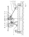
- Figur 1 - einen Längsschnitt durch die Antriebsanordnung für einen Schwingfördertopf, gezogen entlang der Linie C-D in Figur 2
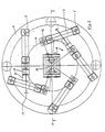
- Figur 2 - eine Draufsicht auf die Antriebsanordnung, gesehen von der Schnittlinie A-B in Figur 1.
- Figur 1 läßt eine kreisrunde Montageplatte 1 erkennen, die mit vier Gummifüßen 2 rutschfest auf einer massiven Stellfläche 3 steht. Auf die Montageplatte 1 sind fünf Befestigungssockel aufgeschweißt, die eine obere, schräggestellte Auflagefläche 6 aufweisen, in die eine Gewindebohrung eingebracht ist Die Montagesockel 5 befinden sich auf einem äußeren Kreis um den Mittelpunkt der Montageplatte 1. Mittels einer durch eine entsprechende Bohrung einer Blattfeder 7 ragenden Befestigungsschraube 8 ist die Blattfeder mit ihrem unteren Ende an dem Montagesockel 5 befestigt, wobei sie flächig auf der Auflagefläche 6 aufliegt. Die abgeschrägte Auflagefläche 6 definiert somit den Winkel der Blattfeder 7 mit der Horizontalen. Das andere Ende der Blattfeder 7 ist mittels einer weiteren Befestigungsschraube 9 an einer Auflagefläche 10 eines Ansatzes 11 eines Zapfen-Drehgelenks 12 befestigt. Der Zapfen 13 des Drehgelenks 12 ist fest mit einer Grundplatte 14 eines (nicht dargestellten) Schwingfördertopfes verbunden. Unterhalb der Grundplatte 14 ist der Zapfen durch eine Abstandshülse 15 umgeben, an die sich nach unten ein drehbar auf dem Zapfen 13 gelagertes Buchsenteil 16 mit dem Ansatz 11 anschließt. Das Buchsenteil 16 ist nach unten durch zwei Muttern 17 gesichert.
- Figur 2 läßt erkennen, daß sich die Drehgelenke 12 auf einem inneren Kreis 18 um den Mittelpunkt M der Montageplatte 1 befinden. Die Blattfedern 7 erstrecken sich mit ihrer Mittelachse etwa in Richtung der Tangente des inneren Kreises 18, die jeweils durch die Drehachse des Drehgelenks 12 läuft. Die Befestigungspunkte der Blattfedern 7 an den Sockeln 6, die durch die Schrauben 8 gebildet sind, liegen auf einem äußeren Kreis, dessen Radius etwa das 1,5fache des Radius des inneren Kreises 18 beträgt. Somit bildet die Mittelachse der Blattfedern 7 mit der den jeweiligen Befestigungspunkt 8 schneidenden Tangente am äußeren Kreis einen Winkel von etwas mehr als 50°.
- Im Mittelpunkt M der Montageplatte 1 ist ein Schwingmagnet 19 angeordnet, der die Grundplatte 14 des Schwingfördertopfes periodisch anzieht und so über die Rückstellkräfte der Blattfedern 7 in Schwingung versetzt. Die Schwingfrequenz des Schwingmagneten 19 liegt zwischen 3 und 8 Hz. Aufgrund der Ankoppelung der Grundplatte 14 über die in der beschriebenen Weise angeordneten Blattfedem 7 an der die Gegenmasse darstellenden Grundplatte 1 wird die Grundplatte 14 in eine rotierende Schwingbewegung versetzt, bei der gleichzeitig eine vertikale Auf- und Abbewegung ausgeführt wird. Die Anlagefläche 6 der Montagesockel 5 steht etwa in einem Winkel von 30° zur Horizontalen, so daß auch die Blattfedern 7 mit ihrer Schwingebene diesen Winkel mit der Horizontalen bilden. Die Bewegung der Grundplatte 14 erfolgt senkrecht zu der Schwingebene der Blattfedern 7, so daß eine Aufwärtsbewegung in einem Winkel von etwa 60° zur Horizontalen entsteht. Dieser Aufwärtsbewegung ist die Rotations-Bahnbewegung in Förderrichtung überlagert.
- Die Grundplatte 14 ist mit der Montageplatte 1 ferner über zwei Dämpfer 20 verbunden, die als geschwindigkeitsabhängige Luftdämpfer ausgebildet sind. Die Luftdämpfer sind am äußeren Umfang eines Teilkreises der Grundplatte 14 (etwa innerer Kreis 18) angelenkt, wobei sich der obere und der untere Anlenkungspunkt 21, 22 in fast gleichen Abständen vom Mittelpunkt M der Montageplatte 1 befindet.
- Die Drehgelenke 12 ermöglichen die gegunüber der tangentialen des äußeren Kreises verdrehten Anordnung der Blattfedern 7, da sie die auf die Grundplatte 14 übertragene Rotationsbewegung aufnehmen. An sich ist die Anordnung eines Zapfenlagers mit einer vertikal stehenden Drehachse nicht ausreichend, da eine weitere Drehkomponente bei der Rotationsbewegung der Grundplatte 14 entsteht. Diese weitere Komponente ist jedoch so gering, daß sie durch das Lagerspiel aufgenommen wird. Es wäre jedoch auch denkbar,statt der Zapfen-Drehgelenke12 Kugelgelenke o. ä. einzusetzen, die einen weiteren Freiheitsgrad haben.
- Mit dem dargestellten Schwingförderer lassen sich Massenteile mit einer definierten Geschwindigkeit und einem gegenüber herkömmlichen Schwingfördertöpfen um Größenordnungen reduzierten Lärm vorfördern. Die Störanfälligkeit ist wesentlich verringert, weil die Teile keiner Wurfbewegung mehr unterworfen werden.
Claims (6)
Priority Applications (1)
| Application Number | Priority Date | Filing Date | Title |
|---|---|---|---|
| AT87104516T ATE53367T1 (de) | 1986-03-26 | 1987-03-26 | Schwingfoerderer nach dem gleitfoerderprinzip. |
Applications Claiming Priority (2)
| Application Number | Priority Date | Filing Date | Title |
|---|---|---|---|
| DE3610139 | 1986-03-26 | ||
| DE19863610139 DE3610139A1 (de) | 1986-03-26 | 1986-03-26 | Schwingfoerderer nach dem gleitfoerderprinzip |
Publications (2)
| Publication Number | Publication Date |
|---|---|
| EP0239114A1 EP0239114A1 (de) | 1987-09-30 |
| EP0239114B1 true EP0239114B1 (de) | 1990-06-06 |
Family
ID=6297284
Family Applications (1)
| Application Number | Title | Priority Date | Filing Date |
|---|---|---|---|
| EP87104516A Expired - Lifetime EP0239114B1 (de) | 1986-03-26 | 1987-03-26 | Schwingförderer nach dem Gleitförderprinzip |
Country Status (4)
| Country | Link |
|---|---|
| EP (1) | EP0239114B1 (de) |
| AT (1) | ATE53367T1 (de) |
| DE (2) | DE3610139A1 (de) |
| ES (1) | ES2015909B3 (de) |
Families Citing this family (2)
| Publication number | Priority date | Publication date | Assignee | Title |
|---|---|---|---|---|
| DE3801956A1 (de) * | 1988-01-23 | 1989-07-27 | Schlafhorst & Co W | Verfahren und vorrichtung zum foerdern von kopsen und huelsen |
| DE4214050A1 (de) * | 1992-04-29 | 1993-11-04 | Guenther Ohrt | Schwingfoerderer, insbesondere schwingrinnenfoerderer |
Family Cites Families (4)
| Publication number | Priority date | Publication date | Assignee | Title |
|---|---|---|---|---|
| DE210209C (de) * | ||||
| AT255966B (de) * | 1965-04-23 | 1967-07-25 | Syntron Company Division Of Li | Zweimassen-Drehschwingungseinrichtung, insbesondere für eine Fördereinrichtung für Massenartikel |
| CA941397A (en) * | 1971-11-12 | 1974-02-05 | Daniel J. Baljet | Spring system for vibratory parts feeders |
| DE3331050A1 (de) * | 1983-08-29 | 1985-03-14 | Rhein-Nadel Automation GmbH, 5100 Aachen | Vorrichtung zur reihenfoermig geordneten zufuhr von werkstuecken mit einem vibrationsantrieb |
-
1986
- 1986-03-26 DE DE19863610139 patent/DE3610139A1/de active Granted
-
1987
- 1987-03-26 AT AT87104516T patent/ATE53367T1/de not_active IP Right Cessation
- 1987-03-26 ES ES87104516T patent/ES2015909B3/es not_active Expired - Lifetime
- 1987-03-26 DE DE8787104516T patent/DE3763057D1/de not_active Expired - Fee Related
- 1987-03-26 EP EP87104516A patent/EP0239114B1/de not_active Expired - Lifetime
Also Published As
| Publication number | Publication date |
|---|---|
| DE3610139A1 (de) | 1987-10-01 |
| DE3763057D1 (de) | 1990-07-12 |
| ATE53367T1 (de) | 1990-06-15 |
| DE3610139C2 (de) | 1990-02-08 |
| ES2015909B3 (es) | 1990-09-16 |
| EP0239114A1 (de) | 1987-09-30 |
Similar Documents
| Publication | Publication Date | Title |
|---|---|---|
| DE60002924T2 (de) | Abstreifer für Förderbänder bei unterschiedlichem Verschleiss | |
| DE3001207C2 (de) | Gelenk-Rotor für Hubschrauber | |
| DE2356933C3 (de) | Straßenfertiger mit an Zugarmen angeschlossener Einbauvorrichtung | |
| DE3402861C2 (de) | ||
| EP2601426B1 (de) | Drehschwingungstilger mit zweiarmigem pendel | |
| EP1142651B1 (de) | Siebvorrichtung | |
| DE2532547B2 (de) | Zweimassen-Rotationsschwingförderer | |
| EP0239114B1 (de) | Schwingförderer nach dem Gleitförderprinzip | |
| EP1899245B1 (de) | Linear-vibrationsförderer | |
| DE3415068A1 (de) | Hubschrauber-rotor | |
| DE1900811A1 (de) | Antrieb fuer einen Schuettelzufuehrer | |
| DE19701403C1 (de) | Mehrblattrotor für ein Drehflügelflugzeug | |
| DE1828880U (de) | Vorrichtung zum ausstreuen koernigen oder pulvrigen materials. | |
| DE8608259U1 (de) | Schwingförderer nach dem Gleitförderprinzip | |
| EP1731451B1 (de) | Schwingsystem für einen Vibrations-Linearförderer zum Fördern eines Fördergutes und Vibrations-Linearförderer | |
| DE3147164C2 (de) | ||
| DE3221422C3 (de) | Einblatt-Windturbine mit Fliehkraftregelung | |
| DE1900811C (de) | Antrieb fur einen Vibrationsförderer | |
| DE1215050B (de) | Foerderer zum Auf- oder Abwaertstransport von Schuettgut | |
| DE435143C (de) | Klassiervorrichtung, deren Sieb mit einer darunter befindlichen Stuetze und einer Ein-richtung zum Erschuettern des Siebes zusammenwirkt und an der Stuetze unbefestigt ist | |
| DE2104514C3 (de) | Elektromagnetischer Vibrator | |
| DE2809367A1 (de) | Reversierbarer schwingfoerderer | |
| AT156225B (de) | Schwingsieb mit Gegengewicht. | |
| DE1675809B1 (de) | Mehrteiliges Kreuzstueck fuer Kardangelenk | |
| DE1248445B (de) | Siebvorrichtung, insbesondere fuer feuchtes oder klebriges Siebgut |
Legal Events
| Date | Code | Title | Description |
|---|---|---|---|
| PUAI | Public reference made under article 153(3) epc to a published international application that has entered the european phase |
Free format text: ORIGINAL CODE: 0009012 |
|
| AK | Designated contracting states |
Kind code of ref document: A1 Designated state(s): AT BE CH DE ES FR GB IT LI NL SE |
|
| 17P | Request for examination filed |
Effective date: 19880318 |
|
| RAP1 | Party data changed (applicant data changed or rights of an application transferred) |
Owner name: FACTRON MASCHINENGESELLSCHAFT MBH + CO. KG |
|
| 17Q | First examination report despatched |
Effective date: 19890613 |
|
| RAP3 | Party data changed (applicant data changed or rights of an application transferred) |
Owner name: FACTRON MASCHINENBAUGESELLSCHAFT MBH + CO. KG |
|
| GRAA | (expected) grant |
Free format text: ORIGINAL CODE: 0009210 |
|
| AK | Designated contracting states |
Kind code of ref document: B1 Designated state(s): AT BE CH DE ES FR GB IT LI NL SE |
|
| REF | Corresponds to: |
Ref document number: 53367 Country of ref document: AT Date of ref document: 19900615 Kind code of ref document: T |
|
| REF | Corresponds to: |
Ref document number: 3763057 Country of ref document: DE Date of ref document: 19900712 |
|
| GBT | Gb: translation of ep patent filed (gb section 77(6)(a)/1977) | ||
| ET | Fr: translation filed | ||
| ITF | It: translation for a ep patent filed | ||
| PLBE | No opposition filed within time limit |
Free format text: ORIGINAL CODE: 0009261 |
|
| STAA | Information on the status of an ep patent application or granted ep patent |
Free format text: STATUS: NO OPPOSITION FILED WITHIN TIME LIMIT |
|
| ITTA | It: last paid annual fee | ||
| 26N | No opposition filed | ||
| ITPR | It: changes in ownership of a european patent |
Owner name: CESSIONE;RIWA PRAEZISIONSTECHNIK GMBH & CO. BETRIE |
|
| REG | Reference to a national code |
Ref country code: CH Ref legal event code: PUE Owner name: RIWA PRAEZISIONSTECHNIK GMBH & CO. BETRIEBS KG Ref country code: CH Ref legal event code: PFA Free format text: FMB-RIWA PRAEZISIONSTECHNIK GMBH & CO. AUTOMATISIERUNGS KG |
|
| REG | Reference to a national code |
Ref country code: GB Ref legal event code: 732 |
|
| BECN | Be: change of holder's name |
Effective date: 19920316 |
|
| PGFP | Annual fee paid to national office [announced via postgrant information from national office to epo] |
Ref country code: BE Payment date: 19930211 Year of fee payment: 7 |
|
| PGFP | Annual fee paid to national office [announced via postgrant information from national office to epo] |
Ref country code: SE Payment date: 19930212 Year of fee payment: 7 |
|
| PGFP | Annual fee paid to national office [announced via postgrant information from national office to epo] |
Ref country code: ES Payment date: 19930223 Year of fee payment: 7 |
|
| PGFP | Annual fee paid to national office [announced via postgrant information from national office to epo] |
Ref country code: FR Payment date: 19930224 Year of fee payment: 7 |
|
| PGFP | Annual fee paid to national office [announced via postgrant information from national office to epo] |
Ref country code: GB Payment date: 19930312 Year of fee payment: 7 |
|
| PGFP | Annual fee paid to national office [announced via postgrant information from national office to epo] |
Ref country code: CH Payment date: 19930329 Year of fee payment: 7 |
|
| PGFP | Annual fee paid to national office [announced via postgrant information from national office to epo] |
Ref country code: NL Payment date: 19930331 Year of fee payment: 7 Ref country code: AT Payment date: 19930331 Year of fee payment: 7 |
|
| PGFP | Annual fee paid to national office [announced via postgrant information from national office to epo] |
Ref country code: DE Payment date: 19930510 Year of fee payment: 7 |
|
| REG | Reference to a national code |
Ref country code: ES Ref legal event code: PC2A Owner name: FMB-RIWA PR ZISIONSTECHNIK GMBH & CO. AUTOMATISIER |
|
| PG25 | Lapsed in a contracting state [announced via postgrant information from national office to epo] |
Ref country code: GB Effective date: 19940326 Ref country code: AT Effective date: 19940326 |
|
| PG25 | Lapsed in a contracting state [announced via postgrant information from national office to epo] |
Ref country code: SE Free format text: LAPSE BECAUSE OF NON-PAYMENT OF DUE FEES Effective date: 19940327 |
|
| PG25 | Lapsed in a contracting state [announced via postgrant information from national office to epo] |
Ref country code: ES Free format text: LAPSE BECAUSE OF NON-PAYMENT OF DUE FEES Effective date: 19940328 |
|
| PG25 | Lapsed in a contracting state [announced via postgrant information from national office to epo] |
Ref country code: LI Effective date: 19940331 Ref country code: CH Effective date: 19940331 Ref country code: BE Effective date: 19940331 |
|
| BERE | Be: lapsed |
Owner name: FMB-RIWA PRAZISIONSTECHNIK G.M.B.H. & CO. AUTOMAT Effective date: 19940331 |
|
| PG25 | Lapsed in a contracting state [announced via postgrant information from national office to epo] |
Ref country code: NL Effective date: 19941001 |
|
| NLV4 | Nl: lapsed or anulled due to non-payment of the annual fee | ||
| GBPC | Gb: european patent ceased through non-payment of renewal fee |
Effective date: 19940326 |
|
| PG25 | Lapsed in a contracting state [announced via postgrant information from national office to epo] |
Ref country code: FR Effective date: 19941130 |
|
| REG | Reference to a national code |
Ref country code: CH Ref legal event code: PL |
|
| PG25 | Lapsed in a contracting state [announced via postgrant information from national office to epo] |
Ref country code: DE Effective date: 19941201 |
|
| REG | Reference to a national code |
Ref country code: FR Ref legal event code: ST |
|
| EUG | Se: european patent has lapsed |
Ref document number: 87104516.7 Effective date: 19941010 |
|
| REG | Reference to a national code |
Ref country code: ES Ref legal event code: FD2A Effective date: 19990301 |
|
| PG25 | Lapsed in a contracting state [announced via postgrant information from national office to epo] |
Ref country code: IT Free format text: LAPSE BECAUSE OF NON-PAYMENT OF DUE FEES;WARNING: LAPSES OF ITALIAN PATENTS WITH EFFECTIVE DATE BEFORE 2007 MAY HAVE OCCURRED AT ANY TIME BEFORE 2007. THE CORRECT EFFECTIVE DATE MAY BE DIFFERENT FROM THE ONE RECORDED. Effective date: 20050326 |