EP0236998B1 - Werkstückträger für zylindrische einseitig offene Werkstücke - Google Patents
Werkstückträger für zylindrische einseitig offene Werkstücke Download PDFInfo
- Publication number
- EP0236998B1 EP0236998B1 EP87103293A EP87103293A EP0236998B1 EP 0236998 B1 EP0236998 B1 EP 0236998B1 EP 87103293 A EP87103293 A EP 87103293A EP 87103293 A EP87103293 A EP 87103293A EP 0236998 B1 EP0236998 B1 EP 0236998B1
- Authority
- EP
- European Patent Office
- Prior art keywords
- pistons
- piston
- recess
- fork
- plate
- Prior art date
- Legal status (The legal status is an assumption and is not a legal conclusion. Google has not performed a legal analysis and makes no representation as to the accuracy of the status listed.)
- Expired - Lifetime
Links
- 238000000465 moulding Methods 0.000 claims description 5
- 239000000463 material Substances 0.000 claims description 3
- 238000004806 packaging method and process Methods 0.000 claims description 3
- 238000002485 combustion reaction Methods 0.000 claims description 2
- 241001125879 Gobio Species 0.000 claims 5
- 238000004519 manufacturing process Methods 0.000 description 2
- 230000015572 biosynthetic process Effects 0.000 description 1
- 238000007664 blowing Methods 0.000 description 1
- 238000013461 design Methods 0.000 description 1
- 238000011161 development Methods 0.000 description 1
- 238000005187 foaming Methods 0.000 description 1
- 238000001746 injection moulding Methods 0.000 description 1
- 238000009434 installation Methods 0.000 description 1
- 238000009413 insulation Methods 0.000 description 1
- 238000012856 packing Methods 0.000 description 1
- 238000012545 processing Methods 0.000 description 1
Images
Classifications
-
- B—PERFORMING OPERATIONS; TRANSPORTING
- B65—CONVEYING; PACKING; STORING; HANDLING THIN OR FILAMENTARY MATERIAL
- B65D—CONTAINERS FOR STORAGE OR TRANSPORT OF ARTICLES OR MATERIALS, e.g. BAGS, BARRELS, BOTTLES, BOXES, CANS, CARTONS, CRATES, DRUMS, JARS, TANKS, HOPPERS, FORWARDING CONTAINERS; ACCESSORIES, CLOSURES, OR FITTINGS THEREFOR; PACKAGING ELEMENTS; PACKAGES
- B65D71/00—Bundles of articles held together by packaging elements for convenience of storage or transport, e.g. portable segregating carrier for plural receptacles such as beer cans or pop bottles; Bales of material
- B65D71/70—Trays provided with projections or recesses in order to assemble multiple articles, e.g. intermediate elements for stacking
Definitions
- the invention relates to a device of the type mentioned in the preamble of the first claim.
- Pistons for installation in piston engines, especially in internal combustion engines, are attached to the connecting rod using a piston pin.
- a piston pin Such an arrangement is shown, for example, in US Pat. No. 4,124,010.
- the piston pin is usually already inserted into the corresponding receiving bore in the piston at the piston manufacturer.
- These pistons are then packed in a folding box by the piston manufacturer, which can hold a certain number of pistons without contact via a plug-in grid.
- the boxes filled in this way are then delivered to the engine manufacturer in mesh boxes.
- a disadvantage of this embodiment is that the pistons cannot be fixed exactly in position within the packing. This can cause damage during transport.
- due to the lack of exact position fixation it is impossible to remove the pistons from the packaging fully automatically and deliver them for further processing, since this requires a very specific piston position. This is due to the fact that the piston pin must be partially pushed out again in order to accommodate the connecting rod.
- the object of the present invention is to provide a workpiece carrier and a transport packaging of the type mentioned at the outset, with which the pistons can be fixed in position. According to the invention, this object is achieved by the characterizing features of the first claim.
- the invention is based on the knowledge that the piston can be slipped over it because of the pin and is thus fixed in position due to the formation of the free pin end over the piston pin.
- the piston crown is then inserted into the recess of the next mold plate, so that the entire piston is thereby fixed both above and below.
- the arrangement of the next mold plate on the piston crown also protects the piston crown, which in the large number of cases has a specific configuration.
- the mold plate itself can be made relatively thin-walled because the pot-like depression does not have to be absorbed by the thickness of the mold plate.
- the molding plate is also particularly suitable for being made of plastic, the deep-drawing or injection molding process having proven to be an outstanding manufacturing process.
- manufacturing by foaming or blowing is also possible. Due to the thin walls of the mold plate and its stackability, the mold plate can be reused. This significantly reduces the disposal costs, since the boxes previously used are only suitable for one-time use.
- the warming-up of the pistons required for connecting rod assembly is simplified in the cold season, since the insulation is no longer required due to the sheathing previously available.
- a thin-walled shaped plate for one-sided hollow cylindrical workpieces is known in general.
- This shaped plate has pot-shaped depressions on its underside, which form sock-like projections with stepped diameter areas on the top. This makes it possible to accommodate hollow cylindrical components of different internal diameters that are open on one side. A fixation of the position of the components in the sense that it acts as an anti-rotation device for the components is not possible with this arrangement.
- the development according to claim 3 has the advantage that the preassembled piston rings can also be immersed in the pot-like recess. This also protects them.
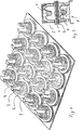
- the mold plate 1 is shown in perspective. It has 16 bases 2 on its upper side - in this example. Each base carries a pin 3, which has a trough 4 in the middle.
- the pins 3 can be conical. Their base circle diameter is chosen so that the pistons to be stacked can be easily attached.
- Fig. 2 shows a schematic cross section through two stacked mold plates 1.
- a piston 5 is placed on the lower mold plate 1.
- the piston 5 is already equipped with a piston pin 6.
- a trough 4 is provided in each pin 3 and is dimensioned such that the piston pin 6 is easily clamped in it by the trough walls.
- the trough depth is designed in such a way that pistons of different heights can be placed securely and the piston skirt always stands on the base 2.
- piston 5 has piston rings 7 that have already been pulled on.
- the pins can have a base circle diameter which corresponds to the inside diameter of the piston. This also keeps the piston at its lower circumference.
Landscapes
- Engineering & Computer Science (AREA)
- Mechanical Engineering (AREA)
- Moulds For Moulding Plastics Or The Like (AREA)
- Buffer Packaging (AREA)
Applications Claiming Priority (2)
| Application Number | Priority Date | Filing Date | Title |
|---|---|---|---|
| DE3608017 | 1986-03-11 | ||
| DE19863608017 DE3608017A1 (de) | 1986-03-11 | 1986-03-11 | Werkstuecktraeger fuer zylindrische, einseitig offene werkstuecke |
Publications (3)
| Publication Number | Publication Date |
|---|---|
| EP0236998A2 EP0236998A2 (de) | 1987-09-16 |
| EP0236998A3 EP0236998A3 (en) | 1988-09-21 |
| EP0236998B1 true EP0236998B1 (de) | 1990-01-17 |
Family
ID=6296034
Family Applications (1)
| Application Number | Title | Priority Date | Filing Date |
|---|---|---|---|
| EP87103293A Expired - Lifetime EP0236998B1 (de) | 1986-03-11 | 1987-03-07 | Werkstückträger für zylindrische einseitig offene Werkstücke |
Country Status (2)
| Country | Link |
|---|---|
| EP (1) | EP0236998B1 (enExample) |
| DE (2) | DE3608017A1 (enExample) |
Families Citing this family (2)
| Publication number | Priority date | Publication date | Assignee | Title |
|---|---|---|---|---|
| DE4135228C2 (de) * | 1991-10-25 | 1996-03-28 | Mtu Muenchen Gmbh | Vorrichtung zur Festlegung von Ladegut |
| AT407373B (de) * | 1998-03-06 | 2001-02-26 | Karl Pawel | Anordnung zum lagebeständigen verpacken von formstücken |
Family Cites Families (11)
| Publication number | Priority date | Publication date | Assignee | Title |
|---|---|---|---|---|
| DE1129884B (de) * | 1956-01-21 | 1962-05-17 | Efka Werke Kiehn Gmbh Fritz | Lager- und Transportbehaelter |
| CH350921A (de) * | 1956-06-18 | 1960-12-15 | Cafag Cartonnagenfabrik Freibu | Verpackung zur Aufnahme von durchbrochenen Gegenständen, z.B. Zifferblättern, und Verfahren zur Herstellung der Verpackung |
| BE670128A (enExample) * | 1965-09-27 | 1966-01-17 | ||
| AT272183B (de) * | 1966-06-08 | 1969-06-25 | Etablissemenet Allemann Praez | Einrichtung zum Magazinieren von zu bearbeitenden Massenteilchen |
| DE6941014U (de) * | 1969-10-21 | 1970-04-09 | Knecht Filterwerke Ges Mit Bes | Ladepalette |
| DE2055344A1 (enExample) * | 1970-11-11 | 1972-05-18 | ||
| DE2217705A1 (de) * | 1971-04-20 | 1972-10-26 | Colgate-Palmolive Co., New York, N.Y. (V.St.A.) | Verpackung für zusammendrückbare Tuben oder ähnliche Behälter |
| DE2143246B2 (de) * | 1971-08-28 | 1973-09-27 | Fa. Richard Heinze, 4900 Herford | Kombinierte Magazin- und Verpackungseinheit für eine Vielzahl von Montageteilen |
| US3949876A (en) * | 1974-09-26 | 1976-04-13 | Aladdin Industries, Incorporated | Articles for beverage service |
| DE2450216A1 (de) * | 1974-10-12 | 1976-05-06 | Nebel Erhard | Paletten |
| US4124010A (en) * | 1976-12-20 | 1978-11-07 | Dana Corporation | Piston pin bore and method of finishing |
-
1986
- 1986-03-11 DE DE19863608017 patent/DE3608017A1/de active Granted
-
1987
- 1987-03-07 DE DE8787103293T patent/DE3761423D1/de not_active Expired - Lifetime
- 1987-03-07 EP EP87103293A patent/EP0236998B1/de not_active Expired - Lifetime
Also Published As
| Publication number | Publication date |
|---|---|
| DE3608017C2 (enExample) | 1988-01-21 |
| EP0236998A3 (en) | 1988-09-21 |
| DE3608017A1 (de) | 1987-09-24 |
| EP0236998A2 (de) | 1987-09-16 |
| DE3761423D1 (de) | 1990-02-22 |
Similar Documents
| Publication | Publication Date | Title |
|---|---|---|
| DE69801081T2 (de) | Baueinheit zum Einsatz in einem Kaffeebrühgerät, sowie deren Filterbehälter und Filterbeutel dafür | |
| DE69001756T2 (de) | Mischkammer zum mischen gasfoermiger und fluessiger komponenten. | |
| DE2720767C2 (enExample) | ||
| DE3300590C2 (de) | Flaschenkasten aus Kunststoff | |
| DE3808065A1 (de) | Stirnwand aus formbarem material fuer eine wickelrolle | |
| DE19500743A1 (de) | Packungsträger für Halbleiter-Bauteile und Herstellungsverfahren hierzu | |
| DE3721902C2 (de) | Verfahren zur Herstellung von axial verlaufenden Rillen am Außenumfang eines Kolbenringes | |
| DE602005004981T2 (de) | Ladeplattform | |
| EP0477575A1 (de) | US-Wandler, insbesondere zur Luft- und Gasdurchflussmessung, und Verfahren zur Herstellung desselben | |
| EP0236998B1 (de) | Werkstückträger für zylindrische einseitig offene Werkstücke | |
| DE3021918C2 (de) | Wärmetauscher, insbesondere für Kraftfahrzeuge | |
| EP0601494B1 (de) | Stirnwand aus Spritzgussmaterial für eine Wickelfolie | |
| DE2849885C2 (de) | Behälter aus Kunststoff | |
| EP0304752B1 (de) | Kochplatten-Stapelhilfe sowie Verfahren zu deren Verwendung | |
| DE3817883A1 (de) | Lenkrad | |
| DE1936152B2 (de) | Formwerkzeug zum bereichsweisen Um hüllen von elektrischen Bauteilen | |
| DE2263785C2 (de) | Vorrichtung zum Blasformen eines Behälters aus thermoplastischem Kunststoff | |
| DE3886954T2 (de) | Einrichtung zum Ineinandergreifen von Platten. | |
| DE19815413B4 (de) | Verfahren zur Herstellung einer Verpackung sowie Verpackung hergestellt nach diesem Verfahren | |
| CH636542A5 (en) | Method for the production of flanged bushes and a flanged bush produced by this method | |
| DE2342249A1 (de) | Nietmutter und verfahren zu deren erzeugung | |
| DE2921516A1 (de) | Palette fuer topfpflanzen | |
| DE2756165C3 (de) | Schaumerzeugungskörper | |
| DE2254442C3 (de) | Vorrichtung zum Ein- oder Ausbauen eines Kolbens einer Kolbenmaschine | |
| DE20116825U1 (de) | Zweischaliges Behältnis für flüssige Werkstoffe |
Legal Events
| Date | Code | Title | Description |
|---|---|---|---|
| PUAI | Public reference made under article 153(3) epc to a published international application that has entered the european phase |
Free format text: ORIGINAL CODE: 0009012 |
|
| AK | Designated contracting states |
Kind code of ref document: A2 Designated state(s): DE FR GB IT SE |
|
| PUAL | Search report despatched |
Free format text: ORIGINAL CODE: 0009013 |
|
| AK | Designated contracting states |
Kind code of ref document: A3 Designated state(s): DE FR GB IT SE |
|
| 17P | Request for examination filed |
Effective date: 19881015 |
|
| 17Q | First examination report despatched |
Effective date: 19881228 |
|
| GRAA | (expected) grant |
Free format text: ORIGINAL CODE: 0009210 |
|
| AK | Designated contracting states |
Kind code of ref document: B1 Designated state(s): DE FR GB IT SE |
|
| REF | Corresponds to: |
Ref document number: 3761423 Country of ref document: DE Date of ref document: 19900222 |
|
| ET | Fr: translation filed | ||
| GBT | Gb: translation of ep patent filed (gb section 77(6)(a)/1977) | ||
| ITF | It: translation for a ep patent filed | ||
| PLBE | No opposition filed within time limit |
Free format text: ORIGINAL CODE: 0009261 |
|
| STAA | Information on the status of an ep patent application or granted ep patent |
Free format text: STATUS: NO OPPOSITION FILED WITHIN TIME LIMIT |
|
| 26N | No opposition filed | ||
| PGFP | Annual fee paid to national office [announced via postgrant information from national office to epo] |
Ref country code: SE Payment date: 19910227 Year of fee payment: 5 |
|
| PGFP | Annual fee paid to national office [announced via postgrant information from national office to epo] |
Ref country code: GB Payment date: 19910306 Year of fee payment: 5 |
|
| PGFP | Annual fee paid to national office [announced via postgrant information from national office to epo] |
Ref country code: FR Payment date: 19910329 Year of fee payment: 5 |
|
| ITTA | It: last paid annual fee | ||
| PG25 | Lapsed in a contracting state [announced via postgrant information from national office to epo] |
Ref country code: GB Effective date: 19920307 |
|
| PG25 | Lapsed in a contracting state [announced via postgrant information from national office to epo] |
Ref country code: SE Effective date: 19920308 |
|
| GBPC | Gb: european patent ceased through non-payment of renewal fee | ||
| PG25 | Lapsed in a contracting state [announced via postgrant information from national office to epo] |
Ref country code: FR Effective date: 19921130 |
|
| REG | Reference to a national code |
Ref country code: FR Ref legal event code: ST |
|
| EUG | Se: european patent has lapsed |
Ref document number: 87103293.4 Effective date: 19921005 |
|
| PGFP | Annual fee paid to national office [announced via postgrant information from national office to epo] |
Ref country code: DE Payment date: 20010809 Year of fee payment: 14 |
|
| PG25 | Lapsed in a contracting state [announced via postgrant information from national office to epo] |
Ref country code: DE Free format text: LAPSE BECAUSE OF NON-PAYMENT OF DUE FEES Effective date: 20020201 |
|
| PG25 | Lapsed in a contracting state [announced via postgrant information from national office to epo] |
Ref country code: IT Free format text: LAPSE BECAUSE OF NON-PAYMENT OF DUE FEES;WARNING: LAPSES OF ITALIAN PATENTS WITH EFFECTIVE DATE BEFORE 2007 MAY HAVE OCCURRED AT ANY TIME BEFORE 2007. THE CORRECT EFFECTIVE DATE MAY BE DIFFERENT FROM THE ONE RECORDED. Effective date: 20050307 |