EP0236109B1 - Multi-jointed robot - Google Patents
Multi-jointed robot Download PDFInfo
- Publication number
- EP0236109B1 EP0236109B1 EP87301801A EP87301801A EP0236109B1 EP 0236109 B1 EP0236109 B1 EP 0236109B1 EP 87301801 A EP87301801 A EP 87301801A EP 87301801 A EP87301801 A EP 87301801A EP 0236109 B1 EP0236109 B1 EP 0236109B1
- Authority
- EP
- European Patent Office
- Prior art keywords
- arm
- motor
- shaft
- drive means
- robot
- Prior art date
- Legal status (The legal status is an assumption and is not a legal conclusion. Google has not performed a legal analysis and makes no representation as to the accuracy of the status listed.)
- Expired - Lifetime
Links
- 239000003638 chemical reducing agent Substances 0.000 description 2
Images


Classifications
-
- B—PERFORMING OPERATIONS; TRANSPORTING
- B25—HAND TOOLS; PORTABLE POWER-DRIVEN TOOLS; MANIPULATORS
- B25J—MANIPULATORS; CHAMBERS PROVIDED WITH MANIPULATION DEVICES
- B25J9/00—Programme-controlled manipulators
- B25J9/02—Programme-controlled manipulators characterised by movement of the arms, e.g. cartesian coordinate type
- B25J9/04—Programme-controlled manipulators characterised by movement of the arms, e.g. cartesian coordinate type by rotating at least one arm, excluding the head movement itself, e.g. cylindrical coordinate type or polar coordinate type
-
- B—PERFORMING OPERATIONS; TRANSPORTING
- B25—HAND TOOLS; PORTABLE POWER-DRIVEN TOOLS; MANIPULATORS
- B25J—MANIPULATORS; CHAMBERS PROVIDED WITH MANIPULATION DEVICES
- B25J9/00—Programme-controlled manipulators
- B25J9/10—Programme-controlled manipulators characterised by positioning means for manipulator elements
- B25J9/1005—Programme-controlled manipulators characterised by positioning means for manipulator elements comprising adjusting means
-
- B—PERFORMING OPERATIONS; TRANSPORTING
- B25—HAND TOOLS; PORTABLE POWER-DRIVEN TOOLS; MANIPULATORS
- B25J—MANIPULATORS; CHAMBERS PROVIDED WITH MANIPULATION DEVICES
- B25J17/00—Joints
-
- B—PERFORMING OPERATIONS; TRANSPORTING
- B25—HAND TOOLS; PORTABLE POWER-DRIVEN TOOLS; MANIPULATORS
- B25J—MANIPULATORS; CHAMBERS PROVIDED WITH MANIPULATION DEVICES
- B25J9/00—Programme-controlled manipulators
- B25J9/02—Programme-controlled manipulators characterised by movement of the arms, e.g. cartesian coordinate type
- B25J9/04—Programme-controlled manipulators characterised by movement of the arms, e.g. cartesian coordinate type by rotating at least one arm, excluding the head movement itself, e.g. cylindrical coordinate type or polar coordinate type
- B25J9/041—Cylindrical coordinate type
- B25J9/042—Cylindrical coordinate type comprising an articulated arm
-
- B—PERFORMING OPERATIONS; TRANSPORTING
- B25—HAND TOOLS; PORTABLE POWER-DRIVEN TOOLS; MANIPULATORS
- B25J—MANIPULATORS; CHAMBERS PROVIDED WITH MANIPULATION DEVICES
- B25J9/00—Programme-controlled manipulators
- B25J9/10—Programme-controlled manipulators characterised by positioning means for manipulator elements
- B25J9/106—Programme-controlled manipulators characterised by positioning means for manipulator elements with articulated links
- B25J9/1065—Programme-controlled manipulators characterised by positioning means for manipulator elements with articulated links with parallelograms
-
- F—MECHANICAL ENGINEERING; LIGHTING; HEATING; WEAPONS; BLASTING
- F16—ENGINEERING ELEMENTS AND UNITS; GENERAL MEASURES FOR PRODUCING AND MAINTAINING EFFECTIVE FUNCTIONING OF MACHINES OR INSTALLATIONS; THERMAL INSULATION IN GENERAL
- F16H—GEARING
- F16H21/00—Gearings comprising primarily only links or levers, with or without slides
- F16H21/10—Gearings comprising primarily only links or levers, with or without slides all movement being in, or parallel to, a single plane
- F16H21/16—Gearings comprising primarily only links or levers, with or without slides all movement being in, or parallel to, a single plane for interconverting rotary motion and reciprocating motion
- F16H21/18—Crank gearings; Eccentric gearings
- F16H21/34—Crank gearings; Eccentric gearings with two or more connecting-rods to each crank or eccentric
-
- H—ELECTRICITY
- H02—GENERATION; CONVERSION OR DISTRIBUTION OF ELECTRIC POWER
- H02K—DYNAMO-ELECTRIC MACHINES
- H02K7/00—Arrangements for handling mechanical energy structurally associated with dynamo-electric machines, e.g. structural association with mechanical driving motors or auxiliary dynamo-electric machines
- H02K7/06—Means for converting reciprocating motion into rotary motion or vice versa
Definitions
- This invention relates generally to robots, and more particularly to a robot with a multi-jointed arm.
- Japanese Patent Disclosure (Kokai) 60-76992 discloses a directly driven multi-jointed robot.
- a first arm pivots in response to a first motor.
- a second arm which is attached to a shaft passing through an aperture in the first arm, is driven by a second motor with a double parallel link mechanism.
- the second motor is set at the pivotal center of the first arm.
- a single crank shaft which is directly driven by the second motor, drives the double parallel link mechanism.
- the crank shaft since the crank shaft is driven at one side of the second motor, the crank shaft is highly stressed. Thus, the shaft must have a high strength and rigidity.
- the second motor is supported on the first arm, the mass and the inertia of the second motor are added to the first arm, and the reaction torque of the second motor is added to the first motor load. Therefore, the first motor requires large torque and large power.
- European patent publication no. EP-A-118012 discloses a robot joint comprising a first arm (16) and second arm (34) which are probably connected by a joint having an integral motor (12), the motor being mounted on the first arm and connected to the second arm, for causing pivotal movement thereof, at both ends of the motor shaft so as to reduce the strain on the motor. In this case also, however, because the motor is incorporated in the joint, its mass must be supported by the first arm.
- the present invention seeks to provide an arrangement which reduces the stress in the crank shaft of a motor of a multi-jointed robot.
- the invention also seeks to reduce the torque and power requirements of a motor for a multi-jointed robot.
- a multi-jointed robot comprising: a first arm pivotable about a first axis, and a second arm pivotably connected to the first arm; first drive means connected to the first arm to cause pivotal movement of said arm about said axis; second drive means connected to said second arm for causing pivotal movement of said second arm relative to said first arm, said second drive means comprising a motor which is connected to the second arm by means of a first pair of crank arms which extend from opposite ends of the motor shaft and are perpendicular to the shaft and to each other, and a second pair of crank arms which extend from opposite ends of the second arm pivot and each of which is parallel to its corresponding first crank arm and is connected to it by a connecting rod.
- Figure 1 is a perspective view of an embodiment of a robot of this invention
- Figure 2 is an elevational sectional view showing the major components of the embodiment shown in Figure 1
- Figure 3 is a plan view of the embodiment shown in Figure 1 to display its motion
- Figure 4 is a partial plan view of the embodiment shown in Figure 1 showing the motion of essential parts
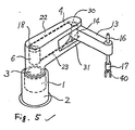
- Figure 5 is a perspective view of another embodiment of a robot of this invention.
- a first motor 1 of low speed and high torque which is fixed on a base 2 has a vertically pivoted shaft 3.
- a first arm 4 is fixed to the shaft 3.
- a supporting frame 5 is fixed to a side of the base 2, and a second motor 6 of low speed and high torque is supported by the supporting frame 5.
- the second motor 6 has two pivotal second-motor shafts 7 and 8, respectively, at its top and bottom, and the first-motor shaft 3 and the second-motor shafts 7 and 8 are arranged coaxially.
- a pair of first-arm bearings 9 and 10 are arranged on the first arm 4, and the first arm 4 and the second motor 6 are pivotably supported with the first-arm bearings 9 and 10.
- Second-arm bearings 11 and 12 are arranged near the tip of the first arm 4, and the second arm 13 is pivotably supported by the second-arm bearing 11 and 12 with a second-arm shaft 14 which is fixed to the second arm 13.
- the first arm 4 has a cavity 15 around the second-arm shaft 14 such that the second arm 13 can pivot without interference with the first arm 4.
- the second-arm shaft 14 is arranged vertically, so that the second arm 13 pivots horizontally as does the first arm 4.
- the second arm 13 has a vertically sliding axis 16 at a tip 41, and the vertically sliding axis 16 has a revolving axis 17.
- the revolving axis 17 has an endeffector 40 at its bottom end which manipulates objects, such as parts to be assembled (not shown).
- a first lever 18 and a second lever 19 are respectively fixed to the second-motor shafts 7 and 8, and extend perpendicular to the shafts 7 and 8, at right angles to each other.
- First and second connecting rods 22 and 23 include tips 20 and 21 which are pivotably connected to the first and the second levers 18 and 19 via shafts 24 and 25 (shown in Fig. 4) and bearings 26 and 27 (not shown), respectively.
- the opposite tips 28 and 29 of the first and the second connecting rods 22 and 23 are likewise pivotably connected to a third lever 30 and a fourth lever 31, respectively, via shafts 32 and 33 (shown in Fig. 4) and bearings (not shown).
- the third lever 30 and the fourth lever 31 are fixed to the top and the bottom,respectively, of the second-arm shaft 14, and extend perpendicular to the second-arm shaft 14, at a right angle to each other.
- the connecting rods 22 and 23 have span adjusters 34 and 35 which are used to adjust the lengths of the connecting rods 22 and 23. This adjustment can make the first lever 18 and the third lever 30, and the second lever 19 and the fourth lever 31 parallel.
- the second arm 13 pivots, as shown at 13c-13-13d in Figs. 3 and 4, in accordance with the movement of the levers 18, 19, 30 and 31, and the connecting rods 22 and 23. Since the first and the second levers 18 and 19, and the third and the fourth levers 30 and 31 are arranged at right angles, there are no "dead points" where the second arm 13 is unstable in position, and the second arm 13 can be freely driven unless the first arm 4 interferes the second arm 13 in the cavity 15.
- the stress in the second motor shafts 7 and 8 is mitigated compared with the stress in the conventional one sided crank shaft.
- the second motor 6 can be supported on the first arm 4, instead of the base 2, as shown in Figure 5.
- stress in the second motor shafts (not shown) is mitigated as in the above described embodiment, although the load on the first motor 1 is not mitigated.
Landscapes
- Engineering & Computer Science (AREA)
- Mechanical Engineering (AREA)
- Robotics (AREA)
- General Engineering & Computer Science (AREA)
- Power Engineering (AREA)
- Manipulator (AREA)
Applications Claiming Priority (2)
| Application Number | Priority Date | Filing Date | Title |
|---|---|---|---|
| JP44131/86 | 1986-03-03 | ||
| JP61044131A JPS62203786A (ja) | 1986-03-03 | 1986-03-03 | 産業用ロボツト |
Publications (2)
| Publication Number | Publication Date |
|---|---|
| EP0236109A1 EP0236109A1 (en) | 1987-09-09 |
| EP0236109B1 true EP0236109B1 (en) | 1991-05-29 |
Family
ID=12683062
Family Applications (1)
| Application Number | Title | Priority Date | Filing Date |
|---|---|---|---|
| EP87301801A Expired - Lifetime EP0236109B1 (en) | 1986-03-03 | 1987-03-02 | Multi-jointed robot |
Country Status (5)
| Country | Link |
|---|---|
| US (1) | US4797061A (ja) |
| EP (1) | EP0236109B1 (ja) |
| JP (1) | JPS62203786A (ja) |
| KR (1) | KR890005092B1 (ja) |
| DE (1) | DE3770292D1 (ja) |
Families Citing this family (19)
| Publication number | Priority date | Publication date | Assignee | Title |
|---|---|---|---|---|
| JPH0261588U (ja) * | 1988-10-24 | 1990-05-08 | ||
| US4949586A (en) * | 1988-11-07 | 1990-08-21 | Intelmatic Corp. | Actuator swing arm mechanism |
| JPH03239483A (ja) * | 1990-02-15 | 1991-10-25 | Fanuc Ltd | 産業用ロボットの駆動機構 |
| IT1251017B (it) * | 1991-05-21 | 1995-04-28 | Ugo Crippa | Meccanismo per compiere traiettorie prefissate assimilabili ad ellittiche |
| JPH05285747A (ja) * | 1992-04-14 | 1993-11-02 | Hirata Kiko Kk | 部品組立装置 |
| JPH07223180A (ja) * | 1994-02-10 | 1995-08-22 | Tescon:Kk | 水平多関節ロボット |
| US5634377A (en) * | 1994-03-09 | 1997-06-03 | Sony Corporation | Articulated robot |
| US5934856A (en) * | 1994-05-23 | 1999-08-10 | Tokyo Electron Limited | Multi-chamber treatment system |
| JP2896108B2 (ja) * | 1995-11-28 | 1999-05-31 | 株式会社神戸製鋼所 | タイヤ加硫機用アンローダ |
| US5672924A (en) * | 1996-10-15 | 1997-09-30 | New York University | Robots using modular direct drive motors |
| JP3360001B2 (ja) * | 1996-10-30 | 2002-12-24 | 芝浦メカトロニクス株式会社 | 処理装置 |
| JP4255663B2 (ja) * | 2002-08-28 | 2009-04-15 | 本田技研工業株式会社 | 脚式移動ロボット |
| JP4635135B2 (ja) * | 2004-06-28 | 2011-02-16 | 学校法人 芝浦工業大学 | 歩行装置 |
| KR101484943B1 (ko) * | 2008-05-30 | 2015-01-21 | 삼성전자 주식회사 | 보행로봇 |
| KR101464125B1 (ko) * | 2008-06-05 | 2014-12-04 | 삼성전자주식회사 | 보행로봇 |
| CN104786224B (zh) * | 2015-04-07 | 2016-11-30 | 上海大学 | 仿人机器人下颚咀嚼运动机构 |
| US10933525B2 (en) * | 2018-07-04 | 2021-03-02 | Fanuc Corporation | Horizontal articulated robot |
| CN110154078B (zh) * | 2019-05-09 | 2022-05-13 | 广东工业大学 | 一种刚柔耦合模块化机器人关节及其应用 |
| CN113183164A (zh) * | 2021-05-10 | 2021-07-30 | 上海工程技术大学 | 一种基于曲柄摇杆机构的仿生机械牛及控制方法 |
Family Cites Families (8)
| Publication number | Priority date | Publication date | Assignee | Title |
|---|---|---|---|---|
| US527671A (en) * | 1894-10-16 | deyoll | ||
| US4034246A (en) * | 1974-12-26 | 1977-07-05 | Akinobu Nakashima | Variable vibrating motor |
| EP0078522B1 (en) * | 1981-10-30 | 1988-05-04 | Hitachi, Ltd. | Industrial robot |
| DE3371609D1 (en) * | 1982-08-30 | 1987-06-25 | Hitachi Ltd | Industrial robot |
| DE3303555A1 (de) * | 1983-02-03 | 1984-08-09 | Müller, Arnold, 7312 Kirchheim | Vorrichtung zur erzeugung von schwenkbewegungen |
| JPS6036192U (ja) * | 1983-08-18 | 1985-03-12 | シルバー精工株式会社 | 産業用ロボット |
| JPS6076992A (ja) * | 1983-09-30 | 1985-05-01 | ぺんてる株式会社 | ロボツトのア−ム駆動装置 |
| DE3440762A1 (de) * | 1984-11-08 | 1986-05-07 | Pittler Maschinenfabrik Ag, 6070 Langen | Vertikal arbeitende werkzeugmaschine mit handhabungsgeraet |
-
1986
- 1986-03-03 JP JP61044131A patent/JPS62203786A/ja active Pending
-
1987
- 1987-02-10 US US07/013,136 patent/US4797061A/en not_active Expired - Fee Related
- 1987-02-26 KR KR1019870001649A patent/KR890005092B1/ko not_active IP Right Cessation
- 1987-03-02 DE DE8787301801T patent/DE3770292D1/de not_active Expired - Lifetime
- 1987-03-02 EP EP87301801A patent/EP0236109B1/en not_active Expired - Lifetime
Also Published As
| Publication number | Publication date |
|---|---|
| EP0236109A1 (en) | 1987-09-09 |
| US4797061A (en) | 1989-01-10 |
| DE3770292D1 (de) | 1991-07-04 |
| JPS62203786A (ja) | 1987-09-08 |
| KR890005092B1 (ko) | 1989-12-11 |
| KR870008667A (ko) | 1987-10-20 |
Similar Documents
| Publication | Publication Date | Title |
|---|---|---|
| EP0236109B1 (en) | Multi-jointed robot | |
| US5054332A (en) | Articulated robot | |
| US7281447B2 (en) | Articulated mechanism comprising a cable reduction gear for use in a robot arm | |
| JPS6312752B2 (ja) | ||
| US4425818A (en) | Robotic manipulator | |
| US4674947A (en) | Industrial robot | |
| CN112917509B (zh) | 一种基于球面并联机构驱动的三自由度机械臂 | |
| JP2542932B2 (ja) | クランク式射出機構 | |
| JPS597593A (ja) | ロボツトの関節装置 | |
| JP3777783B2 (ja) | 水平アームを有するロボット | |
| CN210790980U (zh) | 一种弹簧配重重心后置式曲柄滑杆机械臂 | |
| CN113459071A (zh) | 一种三自由度并联机器人 | |
| CN111633685A (zh) | 一种机械手并联关节 | |
| KR19980034790A (ko) | 수직 다관절 로보트의 아암 연결 구조 | |
| EP0233625B1 (en) | Industrial robot | |
| KR100434771B1 (ko) | 다관절 로보트의 발란서 | |
| JPS61192486A (ja) | 多関節型ア−ム装置 | |
| JPS6161778A (ja) | 産業用ロボツト | |
| CN212601925U (zh) | 一种机械手并联关节 | |
| JPS62251090A (ja) | 産業用ロボツト | |
| JPS6328584A (ja) | 産業用ロボツト | |
| JPH05253882A (ja) | 3自由度の手首を持つロボット | |
| JPS62188687A (ja) | 産業用ロボツト | |
| JPS629880A (ja) | 平行リンク形ロボツトア−ム | |
| JPS62213980A (ja) | 多関節型ロボツトの構造 |
Legal Events
| Date | Code | Title | Description |
|---|---|---|---|
| PUAI | Public reference made under article 153(3) epc to a published international application that has entered the european phase |
Free format text: ORIGINAL CODE: 0009012 |
|
| 17P | Request for examination filed |
Effective date: 19870306 |
|
| AK | Designated contracting states |
Kind code of ref document: A1 Designated state(s): DE FR GB SE |
|
| 17Q | First examination report despatched |
Effective date: 19890410 |
|
| GRAA | (expected) grant |
Free format text: ORIGINAL CODE: 0009210 |
|
| AK | Designated contracting states |
Kind code of ref document: B1 Designated state(s): DE FR GB SE |
|
| ET | Fr: translation filed | ||
| REF | Corresponds to: |
Ref document number: 3770292 Country of ref document: DE Date of ref document: 19910704 |
|
| PLBE | No opposition filed within time limit |
Free format text: ORIGINAL CODE: 0009261 |
|
| STAA | Information on the status of an ep patent application or granted ep patent |
Free format text: STATUS: NO OPPOSITION FILED WITHIN TIME LIMIT |
|
| 26N | No opposition filed | ||
| EAL | Se: european patent in force in sweden |
Ref document number: 87301801.4 |
|
| PGFP | Annual fee paid to national office [announced via postgrant information from national office to epo] |
Ref country code: SE Payment date: 19950315 Year of fee payment: 9 |
|
| PGFP | Annual fee paid to national office [announced via postgrant information from national office to epo] |
Ref country code: FR Payment date: 19960126 Year of fee payment: 10 |
|
| PGFP | Annual fee paid to national office [announced via postgrant information from national office to epo] |
Ref country code: GB Payment date: 19960222 Year of fee payment: 10 |
|
| PG25 | Lapsed in a contracting state [announced via postgrant information from national office to epo] |
Ref country code: SE Effective date: 19960303 |
|
| PGFP | Annual fee paid to national office [announced via postgrant information from national office to epo] |
Ref country code: DE Payment date: 19960313 Year of fee payment: 10 |
|
| EUG | Se: european patent has lapsed |
Ref document number: 87301801.4 |
|
| PG25 | Lapsed in a contracting state [announced via postgrant information from national office to epo] |
Ref country code: GB Effective date: 19970302 |
|
| GBPC | Gb: european patent ceased through non-payment of renewal fee |
Effective date: 19970302 |
|
| PG25 | Lapsed in a contracting state [announced via postgrant information from national office to epo] |
Ref country code: FR Free format text: LAPSE BECAUSE OF NON-PAYMENT OF DUE FEES Effective date: 19971128 |
|
| PG25 | Lapsed in a contracting state [announced via postgrant information from national office to epo] |
Ref country code: DE Effective date: 19971202 |
|
| REG | Reference to a national code |
Ref country code: FR Ref legal event code: ST |