EP0235493A1 - Profilé composite thermiquement isolant - Google Patents
Profilé composite thermiquement isolant Download PDFInfo
- Publication number
- EP0235493A1 EP0235493A1 EP86810095A EP86810095A EP0235493A1 EP 0235493 A1 EP0235493 A1 EP 0235493A1 EP 86810095 A EP86810095 A EP 86810095A EP 86810095 A EP86810095 A EP 86810095A EP 0235493 A1 EP0235493 A1 EP 0235493A1
- Authority
- EP
- European Patent Office
- Prior art keywords
- grooves
- webs
- plastic
- teeth
- toothing
- Prior art date
- Legal status (The legal status is an assumption and is not a legal conclusion. Google has not performed a legal analysis and makes no representation as to the accuracy of the status listed.)
- Granted
Links
Images
Classifications
-
- E—FIXED CONSTRUCTIONS
- E06—DOORS, WINDOWS, SHUTTERS, OR ROLLER BLINDS IN GENERAL; LADDERS
- E06B—FIXED OR MOVABLE CLOSURES FOR OPENINGS IN BUILDINGS, VEHICLES, FENCES OR LIKE ENCLOSURES IN GENERAL, e.g. DOORS, WINDOWS, BLINDS, GATES
- E06B3/00—Window sashes, door leaves, or like elements for closing wall or like openings; Layout of fixed or moving closures, e.g. windows in wall or like openings; Features of rigidly-mounted outer frames relating to the mounting of wing frames
- E06B3/04—Wing frames not characterised by the manner of movement
- E06B3/263—Frames with special provision for insulation
- E06B3/26301—Frames with special provision for insulation with prefabricated insulating strips between two metal section members
- E06B3/26305—Connection details
- E06B3/26307—Insulating strips and metal section members both having L-shaped ribs, the engagement being made by a movement transversal to the plane of the strips
-
- E—FIXED CONSTRUCTIONS
- E06—DOORS, WINDOWS, SHUTTERS, OR ROLLER BLINDS IN GENERAL; LADDERS
- E06B—FIXED OR MOVABLE CLOSURES FOR OPENINGS IN BUILDINGS, VEHICLES, FENCES OR LIKE ENCLOSURES IN GENERAL, e.g. DOORS, WINDOWS, BLINDS, GATES
- E06B3/00—Window sashes, door leaves, or like elements for closing wall or like openings; Layout of fixed or moving closures, e.g. windows in wall or like openings; Features of rigidly-mounted outer frames relating to the mounting of wing frames
- E06B3/04—Wing frames not characterised by the manner of movement
- E06B3/263—Frames with special provision for insulation
- E06B3/26301—Frames with special provision for insulation with prefabricated insulating strips between two metal section members
- E06B3/26305—Connection details
- E06B2003/26314—Provisions for reducing the shift between the strips and the metal section members
-
- E—FIXED CONSTRUCTIONS
- E06—DOORS, WINDOWS, SHUTTERS, OR ROLLER BLINDS IN GENERAL; LADDERS
- E06B—FIXED OR MOVABLE CLOSURES FOR OPENINGS IN BUILDINGS, VEHICLES, FENCES OR LIKE ENCLOSURES IN GENERAL, e.g. DOORS, WINDOWS, BLINDS, GATES
- E06B3/00—Window sashes, door leaves, or like elements for closing wall or like openings; Layout of fixed or moving closures, e.g. windows in wall or like openings; Features of rigidly-mounted outer frames relating to the mounting of wing frames
- E06B3/04—Wing frames not characterised by the manner of movement
- E06B3/263—Frames with special provision for insulation
- E06B3/273—Frames with special provision for insulation with prefabricated insulating elements held in position by deformation of portions of the metal frame members
-
- Y—GENERAL TAGGING OF NEW TECHNOLOGICAL DEVELOPMENTS; GENERAL TAGGING OF CROSS-SECTIONAL TECHNOLOGIES SPANNING OVER SEVERAL SECTIONS OF THE IPC; TECHNICAL SUBJECTS COVERED BY FORMER USPC CROSS-REFERENCE ART COLLECTIONS [XRACs] AND DIGESTS
- Y10—TECHNICAL SUBJECTS COVERED BY FORMER USPC
- Y10T—TECHNICAL SUBJECTS COVERED BY FORMER US CLASSIFICATION
- Y10T428/00—Stock material or miscellaneous articles
- Y10T428/23—Sheet including cover or casing
- Y10T428/233—Foamed or expanded material encased
-
- Y—GENERAL TAGGING OF NEW TECHNOLOGICAL DEVELOPMENTS; GENERAL TAGGING OF CROSS-SECTIONAL TECHNOLOGIES SPANNING OVER SEVERAL SECTIONS OF THE IPC; TECHNICAL SUBJECTS COVERED BY FORMER USPC CROSS-REFERENCE ART COLLECTIONS [XRACs] AND DIGESTS
- Y10—TECHNICAL SUBJECTS COVERED BY FORMER USPC
- Y10T—TECHNICAL SUBJECTS COVERED BY FORMER US CLASSIFICATION
- Y10T428/00—Stock material or miscellaneous articles
- Y10T428/23—Sheet including cover or casing
- Y10T428/237—Noninterengaged fibered material encased [e.g., mat, batt, etc.]
-
- Y—GENERAL TAGGING OF NEW TECHNOLOGICAL DEVELOPMENTS; GENERAL TAGGING OF CROSS-SECTIONAL TECHNOLOGIES SPANNING OVER SEVERAL SECTIONS OF THE IPC; TECHNICAL SUBJECTS COVERED BY FORMER USPC CROSS-REFERENCE ART COLLECTIONS [XRACs] AND DIGESTS
- Y10—TECHNICAL SUBJECTS COVERED BY FORMER USPC
- Y10T—TECHNICAL SUBJECTS COVERED BY FORMER US CLASSIFICATION
- Y10T428/00—Stock material or miscellaneous articles
- Y10T428/23—Sheet including cover or casing
- Y10T428/239—Complete cover or casing
Definitions
- the invention relates to a heat-insulating composite profile for windows, doors and / or facades, in which two profile parts made of metal are kept at a distance from one another by webs of poorly heat-conducting plastic, the plastic webs engaging in grooves of the metal parts with angled anchoring strips, and furthermore the grooves are provided with a tooth-like structure.
- Composite profiles of the type mentioned are known for example from DE-C2-23 66 421 or EP-A-01 23 110;
- the tooth-like structure in the grooves which consists of an embossed corrugation or pressed-in indentations or teeth, serves to improve the shear strength in the axial direction.
- the connection of the webs, which are angled to absorb the transverse tensile forces, with the metal parts is thereby ensured that the insulating webs are drawn into undercut grooves in the longitudinal direction and are fixed by pressing on a flank of the metal part.
- the tooth-like structure should press into the plastic, which is partly compressed and partly displaced.
- the heat-insulating webs have recently been made from fiber-reinforced plastic, in particular from glass-fiber-reinforced polyamide. It has been shown that a tooth-like structure is only impressed to an insufficient extent in fiber-reinforced plastic, so that the axial shear strength is reduced in an impermissible manner and is not reliable enough. In known profiles, therefore, by adding additional elements (see, for example, EP-A-00 85 410) and / or with the aid of an adhesive (EP-A-00 43 968), a better form fit and a higher shear strength have been sought. Additional work steps for introducing the additional material and / or the adhesive and for curing an adhesive connection make the profile production considerably more complicated and complex.
- the object of the invention is to improve the bond between metal parts and fiber-reinforced webs, especially in the case of highly thermally insulated composite profiles, in which particularly high demands are placed on strength and durability, since their webs have a 5 to 8 times the height of those previously common profiles and higher due to larger temperature differences Have shear loads. Furthermore, the manufacture of composite profiles of this type is to be simplified, the space requirement and the number of operations being reduced above all.
- a toothing is cut in the side flanks of the grooves, the teeth of which run in the direction perpendicular to the reference plane defined by the longitudinal thrust and the transverse tensile force, and also that the anchoring strips are made of fiber-reinforced plastic, in particular glass-fiber-reinforced polyamide Bridges are pressed into the teeth by pressing in the direction of the teeth by means of at least partially machining shaping in the plastic and are anchored in it without adhesive, without the bars engaging behind undercuts in the grooves for the positive connection.
- a space-saving and labor-saving manufacturing process for the new composite profiles is characterized in that the toothing is cut into the side flanks of the grooves of the metal parts by means of a hardened punch or reamer, and that the anchoring strips of the webs are then in the direction perpendicular to the longitudinal thrust and the transverse tensile force defined reference plane are pressed into the toothed groove.
- the cutting shape which is achieved by the teeth in the fiber-reinforced plastic, ensures a high strength of the composite and thus a high shear strength in the axial direction; the lack of undercuts for a positive connection allows the bond between metal and plastic to be pressed in by pressing in the direction perpendicular to the plane of the profile defined by longitudinal thrust and transverse tensile force put. A retraction of the webs in the longitudinal direction of the profile can thus be omitted. The space required for the assembly of the composite profile is thus reduced to about the profile length, i.e. to a little less than half.
- the metal legs of the groove are slightly expanded apart from the cutting deformation of the plastic; this creates a preload in the bond area, which increases the safety of the positive and non-positive connection even in the event of large temperature differences in practical use.
- a bending tab can advantageously be provided as additional securing of the composite.
- the transverse tensile force is transmitted eccentrically from the webs; it is therefore appropriate if a longitudinally extending cam is attached to the end faces of the strips, which cam in a corresponding recess of the groove engages. By engaging in the recess, the cam clamps the angled anchoring strip in the groove and prevents inadmissible deformation of the plastic web.
- the material "shifting" cutting and press-in processes can be considerably facilitated if the groove has an undercut that adjoins the "inner" ends of the teeth and / or if the groove and / or the strips are at the rear end of the toothing in the press-in direction are provided with collecting grooves for the admission of the shaved plastic chips.
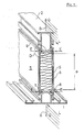
- the new composite profile which is used, for example, as a frame profile of a window, has two metal profile parts 1 and 2, preferably made of aluminum, for the necessary mechanical strength.
- plate-like webs 5 made of glass fiber reinforced polyamide are provided, between which 6 foam or mineral fiber material are additionally embedded as insulation material.
- the web connection can absorb transverse tensile forces Q, its ends are angled to anchoring strips 7, which are pressed into grooves 8 in the metal parts 1 and 2.
- the longitudinal shear forces L are also transmitted from the webs 5 to the metal parts 1 and 2 or vice versa in the composite area D.
- highly insulating metal-plastic composite profiles with a distance a between the metal parts 1 and 2 of at least 40 mm (EP-A1-01 17 885)
- there is a large difference in thermal expansion and due to the large temperature difference between the outer and inner profile parts 1 and 2 thus a large longitudinal shear stress on the plastic webs 5 and the composite zone D can also be expected.
- the direction of the two forces L and Q define the reference plane B, which runs parallel to the surfaces of the webs 5;
- the teeth 10 and the press-in direction E for the webs 5 and the strips 7 run perpendicular to this plane B into the grooves 8.
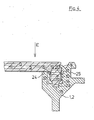
- a bending tab 9 is provided on the metal parts 1 and 2, which at the end of the press-in process for the anchoring strips 7 to be described in the grooves 8 against a rear shoulder 11 (FIG. 4) the last 7 is pressed.
- the tab 9 prevents the strips 7 from sliding out of the grooves 8; in practical use, it is not subjected to any loads.
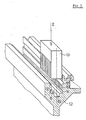
- the first step for the production of the new composite profile consists in cutting the toothing 10 into the side flanks 12 (FIG. 1) of the grooves 8 in the metal profile parts 1 and 2.
- the toothing 10 is cut in both side flanks 12 of the groove 8 by a hardened punch or reamer 13, for example made of steel, which penetrates into the groove 8 in the pressing direction E.
- a hardened punch or reamer 13 for example made of steel
- the undercut 14 in the groove 8 which on the one hand ensures that the metal chips peeled off by the punch 13 between the teeth 10 are torn off and second, these metal chips are "stored” until they are removed, e.g. blown out.
- 14 there is a rectangular depression 15, the function of which will be described later.
- longitudinal grooves 16 and 17 are provided for receiving the plastic of the webs 5 machined when pressed in, as will be described later.
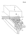
- Fig. 3 shows the beginning of the second operation in the manufacture of the composite, in which an anchoring strip 7 is pressed into the teeth 10 of the groove 8 by a press 18 in the same direction E as the teeth 10.
- the teeth 10 in the harder metal parts 1 and 2 cut a corresponding counter-toothing in the side flanks of the strips 7, the resulting chips being stored in collecting grooves 16 and 17 of the metal parts 1 and 2 and 19 and 20 at the foot of the anchoring strips 7.
- the plastic webs 5 can be pressed in at the same time in all four composite areas D - and advantageously over the entire profile length - with the aid of a correspondingly equipped press brake 18. will. Because of the material-related non-ideal cutting relationships between the strip 7 and the metal profile part 1 or 2, in addition to the machining deformation of the plastic, the legs 24, 25 (FIG. 4) of the groove 8 are also slightly expanded. The resulting preload in bond zone D ensures a secure positive and non-positive connection even in the event of large temperature fluctuations in practical use.
- a nose 21 on the outside of the press 18 bends the bending tab 9 in the direction of the web 5, this tab 9 resting on a shoulder 22 on the outer boundary of the web 5.
- the strip 7 engages in the aforementioned recess 15 in the bottom of the groove 8 of the metal profiles 1 and 2.
- the cam 23 clamps the anchoring strip 7 of the plastic web 5 in the metal profile 1 or 2 and thus absorbs the moment caused by the eccentric attack of the transverse tensile force Q in the strip 7.
- Lugs 23 and depression 15 thus prevent impermissible deformation of the plastic profile as a result of the eccentric attack of the transverse tensile forces Q.
Priority Applications (9)
| Application Number | Priority Date | Filing Date | Title |
|---|---|---|---|
| AT86810095T ATE47193T1 (de) | 1986-02-25 | 1986-02-25 | Waermedaemmendes verbundprofil. |
| EP86810095A EP0235493B1 (fr) | 1986-02-25 | 1986-02-25 | Profilé composite thermiquement isolant |
| DE8686810095T DE3666259D1 (en) | 1986-02-25 | 1986-02-25 | Thermally insulating composite profile member |
| DK007087A DK165992C (da) | 1986-02-25 | 1987-01-07 | Varmeisolerende, sammensat profil og fremgangsmaade til fremstilling af det sammensatte profil |
| FI870195A FI83254C (fi) | 1986-02-25 | 1987-01-19 | Vaermeisolerande lamellprofil och foerfarande foer dess tillverkning. |
| US07/015,289 US4786539A (en) | 1986-02-25 | 1987-02-17 | Thermal insulating composite laminate |
| JP62041219A JPH0730657B2 (ja) | 1986-02-25 | 1987-02-24 | 断熱作用を有する型抜き材枠構造及びその製作方法 |
| CA000530437A CA1286471C (fr) | 1986-02-25 | 1987-02-24 | Composite multicouche thermo-isolant |
| NO870753A NO166668C (no) | 1986-02-25 | 1987-02-24 | Varmeisolerende, sammensatt profil, og fremgangsmaate ved fremstilling av samme. |
Applications Claiming Priority (1)
| Application Number | Priority Date | Filing Date | Title |
|---|---|---|---|
| EP86810095A EP0235493B1 (fr) | 1986-02-25 | 1986-02-25 | Profilé composite thermiquement isolant |
Publications (2)
| Publication Number | Publication Date |
|---|---|
| EP0235493A1 true EP0235493A1 (fr) | 1987-09-09 |
| EP0235493B1 EP0235493B1 (fr) | 1989-10-11 |
Family
ID=8196453
Family Applications (1)
| Application Number | Title | Priority Date | Filing Date |
|---|---|---|---|
| EP86810095A Expired EP0235493B1 (fr) | 1986-02-25 | 1986-02-25 | Profilé composite thermiquement isolant |
Country Status (9)
| Country | Link |
|---|---|
| US (1) | US4786539A (fr) |
| EP (1) | EP0235493B1 (fr) |
| JP (1) | JPH0730657B2 (fr) |
| AT (1) | ATE47193T1 (fr) |
| CA (1) | CA1286471C (fr) |
| DE (1) | DE3666259D1 (fr) |
| DK (1) | DK165992C (fr) |
| FI (1) | FI83254C (fr) |
| NO (1) | NO166668C (fr) |
Cited By (1)
| Publication number | Priority date | Publication date | Assignee | Title |
|---|---|---|---|---|
| FR2922990A1 (fr) * | 2007-10-31 | 2009-05-01 | Norsk Hydro As | Barre isolante, de type profile, destinee a etre associee a une barre metallique, de type profile, par une liaison complete, et barre de construction ainsi obtenue |
Families Citing this family (8)
| Publication number | Priority date | Publication date | Assignee | Title |
|---|---|---|---|---|
| US4892770A (en) * | 1988-08-10 | 1990-01-09 | Davidson Textron Inc. | Interior trim foam product and method of fabrication thereof |
| US5469683A (en) * | 1994-02-09 | 1995-11-28 | Kawneer Company, Inc. | Thermally insulating composite frame member with snap-in thermal isolator |
| US8617702B2 (en) | 2010-04-28 | 2013-12-31 | Sabic Innovative Plastics Ip B.V. | Thermally insulated structural members, and doors and windows incorporating them |
| US9133614B2 (en) * | 2011-11-14 | 2015-09-15 | Oldcastle Buildingenvelope, Inc. | Method and system for thermal barrier installation |
| WO2015006847A1 (fr) | 2013-07-19 | 2015-01-22 | Litezone Technologies Inc. | Unité de vitre à pression compensée |
| US10125537B2 (en) * | 2014-07-18 | 2018-11-13 | Litezone Technologies Inc. | Pressure compensated glass unit |
| EP3396096B1 (fr) * | 2017-04-28 | 2020-02-19 | RP Technik GmbH Profilsysteme | Profilé composite et son procédé de fabrication |
| US10370893B2 (en) * | 2017-09-15 | 2019-08-06 | Arconic Inc. | Apparatus and method for assembly of structural profiles and resultant structures |
Citations (5)
| Publication number | Priority date | Publication date | Assignee | Title |
|---|---|---|---|---|
| FR2312615A1 (fr) * | 1975-05-27 | 1976-12-24 | Capitol Prod Corp | Profile isolant et son application pour la realisation d'un element de construction calorifuge |
| DE2741905A1 (de) * | 1977-09-17 | 1979-03-22 | Volkmar Heuser | Waermeisolierender rahmenschenkel fuer fenster, tueren o.dgl. |
| DE2744553A1 (de) * | 1977-10-04 | 1979-04-05 | Hartmann & Co W | Verfahren zur herstellung von verbundprofilstaeben und hierzu verwendetes stegprofil |
| EP0032408A2 (fr) * | 1978-03-20 | 1981-07-22 | Helmar Dr. Dr. Nahr | Profilé composite thermiquement isolant |
| EP0059458A1 (fr) * | 1981-02-27 | 1982-09-08 | Tefo Ag | Dispositif de liaison |
Family Cites Families (2)
| Publication number | Priority date | Publication date | Assignee | Title |
|---|---|---|---|---|
| DE2904192C2 (de) * | 1979-02-05 | 1982-03-25 | Fa. Eduard Hueck, 5880 Lüdenscheid | Verfahren zur Herstellung eines Verbundprofils für Fensterrahmen, Türrahmen, Fassadenkonstruktionen o.dgl. |
| JPS5758676U (fr) * | 1980-09-25 | 1982-04-06 |
-
1986
- 1986-02-25 AT AT86810095T patent/ATE47193T1/de active
- 1986-02-25 DE DE8686810095T patent/DE3666259D1/de not_active Expired
- 1986-02-25 EP EP86810095A patent/EP0235493B1/fr not_active Expired
-
1987
- 1987-01-07 DK DK007087A patent/DK165992C/da not_active IP Right Cessation
- 1987-01-19 FI FI870195A patent/FI83254C/fi not_active IP Right Cessation
- 1987-02-17 US US07/015,289 patent/US4786539A/en not_active Expired - Lifetime
- 1987-02-24 JP JP62041219A patent/JPH0730657B2/ja not_active Expired - Lifetime
- 1987-02-24 CA CA000530437A patent/CA1286471C/fr not_active Expired - Lifetime
- 1987-02-24 NO NO870753A patent/NO166668C/no unknown
Patent Citations (5)
| Publication number | Priority date | Publication date | Assignee | Title |
|---|---|---|---|---|
| FR2312615A1 (fr) * | 1975-05-27 | 1976-12-24 | Capitol Prod Corp | Profile isolant et son application pour la realisation d'un element de construction calorifuge |
| DE2741905A1 (de) * | 1977-09-17 | 1979-03-22 | Volkmar Heuser | Waermeisolierender rahmenschenkel fuer fenster, tueren o.dgl. |
| DE2744553A1 (de) * | 1977-10-04 | 1979-04-05 | Hartmann & Co W | Verfahren zur herstellung von verbundprofilstaeben und hierzu verwendetes stegprofil |
| EP0032408A2 (fr) * | 1978-03-20 | 1981-07-22 | Helmar Dr. Dr. Nahr | Profilé composite thermiquement isolant |
| EP0059458A1 (fr) * | 1981-02-27 | 1982-09-08 | Tefo Ag | Dispositif de liaison |
Cited By (3)
| Publication number | Priority date | Publication date | Assignee | Title |
|---|---|---|---|---|
| FR2922990A1 (fr) * | 2007-10-31 | 2009-05-01 | Norsk Hydro As | Barre isolante, de type profile, destinee a etre associee a une barre metallique, de type profile, par une liaison complete, et barre de construction ainsi obtenue |
| EP2055883A2 (fr) | 2007-10-31 | 2009-05-06 | Norsk Hydro ASA | Procédé de fabrication d'une barre de construction par sertissage, et barre de construction ainsi obtenue |
| EP2055883A3 (fr) * | 2007-10-31 | 2011-01-19 | Norsk Hydro ASA | Procédé de fabrication d'une barre de construction par sertissage, et barre de construction ainsi obtenue |
Also Published As
| Publication number | Publication date |
|---|---|
| NO870753D0 (no) | 1987-02-24 |
| JPH0730657B2 (ja) | 1995-04-10 |
| FI83254B (fi) | 1991-02-28 |
| NO166668C (no) | 1991-08-21 |
| FI870195A (fi) | 1987-08-26 |
| JPS62202186A (ja) | 1987-09-05 |
| DK7087D0 (da) | 1987-01-07 |
| DK7087A (da) | 1987-08-26 |
| EP0235493B1 (fr) | 1989-10-11 |
| NO870753L (no) | 1987-08-26 |
| CA1286471C (fr) | 1991-07-23 |
| DK165992B (da) | 1993-02-22 |
| US4786539A (en) | 1988-11-22 |
| FI83254C (fi) | 1991-06-10 |
| NO166668B (no) | 1991-05-13 |
| ATE47193T1 (de) | 1989-10-15 |
| DK165992C (da) | 1993-07-05 |
| DE3666259D1 (en) | 1989-11-16 |
| FI870195A0 (fi) | 1987-01-19 |
Similar Documents
| Publication | Publication Date | Title |
|---|---|---|
| EP2476853B1 (fr) | Profil composite pour fenêtres, portes et façades et son procédé de fabrication | |
| EP1555376A1 (fr) | Profilé composite | |
| EP1024243A2 (fr) | Connection resistante au feu avec âme isolante | |
| DE10326503A1 (de) | Aluminium-Verbundprofil für Fenster- oder Türrahmen | |
| EP0235493B1 (fr) | Profilé composite thermiquement isolant | |
| EP1138864B1 (fr) | Profilé composite pour fenêtres, façades, portes ou toiture vitrée | |
| EP0043968B1 (fr) | Profilé composite, notamment pour fenêtres, portes ou similaires | |
| EP0261159B1 (fr) | Profile composite | |
| DE3101630C2 (de) | Verbindung von formstabilen Elementen | |
| EP2325431B1 (fr) | Procédé de fabrication d'un profilé composite à isolation thermique | |
| EP0551836A1 (fr) | Raccord à vis entre un profilé et une ferrure ou un autre élément de construction | |
| DE7511558U (de) | Waermeisoliertes aluminiumprofil fuer aussenwandkonstruktionen | |
| DE3702004C2 (fr) | ||
| EP0952270B2 (fr) | Profilés support pour façades en forme de montant/traverse, auvents, galeries de toit ou analogues | |
| DE19828188C1 (de) | Fassadenprofil | |
| DE2826783C2 (de) | Verbundprofil, insbesondere für Fenster, Türen o.dgl. | |
| DE2821096C2 (fr) | ||
| EP1215360B9 (fr) | Profilé composite | |
| EP1837095A2 (fr) | Profilé métallique pour constructions de cadres d'éléments de fenêtre, porte ou façade tout comme son procédé de fabrication | |
| EP1199481A1 (fr) | Liaison transversale pour des barres profilées | |
| EP0748919A2 (fr) | Raccord en T pour la partie métallique extérieure de profilés isolés pour portes, fenêtres ou façades | |
| DE102020106891B4 (de) | T-Verbindung zwischen einem Pfosten- und Riegelprofil und Pfosten-Riegel-Konstruktion mit einer derartigen T-Verbindung | |
| EP1698736B1 (fr) | Façade et méthode de construction de façade | |
| DE19740461C2 (de) | Verfahren und Verbindungssystem zur unlösbaren Verbindung von Profilen oder Profilelementen | |
| EP0540982A1 (fr) | Joint d'angle pour profils creux d'une fenêtre, porte, façade ou des choses pareilles |
Legal Events
| Date | Code | Title | Description |
|---|---|---|---|
| PUAI | Public reference made under article 153(3) epc to a published international application that has entered the european phase |
Free format text: ORIGINAL CODE: 0009012 |
|
| AK | Designated contracting states |
Kind code of ref document: A1 Designated state(s): AT BE CH DE FR GB IT LI LU NL SE |
|
| RBV | Designated contracting states (corrected) |
Designated state(s): AT BE CH DE FR GB IT LI NL SE |
|
| 17P | Request for examination filed |
Effective date: 19880119 |
|
| 17Q | First examination report despatched |
Effective date: 19880819 |
|
| GRAA | (expected) grant |
Free format text: ORIGINAL CODE: 0009210 |
|
| AK | Designated contracting states |
Kind code of ref document: B1 Designated state(s): AT BE CH DE FR GB IT LI NL SE |
|
| REF | Corresponds to: |
Ref document number: 47193 Country of ref document: AT Date of ref document: 19891015 Kind code of ref document: T |
|
| ITF | It: translation for a ep patent filed |
Owner name: ING. ZINI MARANESI & C. S.R.L. |
|
| GBT | Gb: translation of ep patent filed (gb section 77(6)(a)/1977) | ||
| REF | Corresponds to: |
Ref document number: 3666259 Country of ref document: DE Date of ref document: 19891116 |
|
| ET | Fr: translation filed | ||
| PLBE | No opposition filed within time limit |
Free format text: ORIGINAL CODE: 0009261 |
|
| STAA | Information on the status of an ep patent application or granted ep patent |
Free format text: STATUS: NO OPPOSITION FILED WITHIN TIME LIMIT |
|
| 26N | No opposition filed | ||
| ITTA | It: last paid annual fee | ||
| PGFP | Annual fee paid to national office [announced via postgrant information from national office to epo] |
Ref country code: FR Payment date: 19950113 Year of fee payment: 10 |
|
| PGFP | Annual fee paid to national office [announced via postgrant information from national office to epo] |
Ref country code: SE Payment date: 19950116 Year of fee payment: 10 Ref country code: AT Payment date: 19950116 Year of fee payment: 10 |
|
| PGFP | Annual fee paid to national office [announced via postgrant information from national office to epo] |
Ref country code: GB Payment date: 19950119 Year of fee payment: 10 Ref country code: DE Payment date: 19950119 Year of fee payment: 10 |
|
| PGFP | Annual fee paid to national office [announced via postgrant information from national office to epo] |
Ref country code: BE Payment date: 19950126 Year of fee payment: 10 |
|
| EAL | Se: european patent in force in sweden |
Ref document number: 86810095.9 |
|
| PGFP | Annual fee paid to national office [announced via postgrant information from national office to epo] |
Ref country code: CH Payment date: 19950223 Year of fee payment: 10 |
|
| PGFP | Annual fee paid to national office [announced via postgrant information from national office to epo] |
Ref country code: NL Payment date: 19950228 Year of fee payment: 10 |
|
| PG25 | Lapsed in a contracting state [announced via postgrant information from national office to epo] |
Ref country code: GB Effective date: 19960225 Ref country code: AT Effective date: 19960225 |
|
| PG25 | Lapsed in a contracting state [announced via postgrant information from national office to epo] |
Ref country code: SE Effective date: 19960226 |
|
| PG25 | Lapsed in a contracting state [announced via postgrant information from national office to epo] |
Ref country code: LI Free format text: LAPSE BECAUSE OF NON-PAYMENT OF DUE FEES Effective date: 19960228 Ref country code: CH Free format text: LAPSE BECAUSE OF NON-PAYMENT OF DUE FEES Effective date: 19960228 Ref country code: BE Effective date: 19960228 |
|
| BERE | Be: lapsed |
Owner name: GEILINGER A.G. Effective date: 19960228 |
|
| PG25 | Lapsed in a contracting state [announced via postgrant information from national office to epo] |
Ref country code: NL Effective date: 19960901 |
|
| REG | Reference to a national code |
Ref country code: CH Ref legal event code: PL |
|
| GBPC | Gb: european patent ceased through non-payment of renewal fee |
Effective date: 19960225 |
|
| PG25 | Lapsed in a contracting state [announced via postgrant information from national office to epo] |
Ref country code: FR Effective date: 19961031 |
|
| NLV4 | Nl: lapsed or anulled due to non-payment of the annual fee |
Effective date: 19960901 |
|
| PG25 | Lapsed in a contracting state [announced via postgrant information from national office to epo] |
Ref country code: DE Effective date: 19961101 |
|
| REG | Reference to a national code |
Ref country code: FR Ref legal event code: ST |
|
| PG25 | Lapsed in a contracting state [announced via postgrant information from national office to epo] |
Ref country code: IT Free format text: LAPSE BECAUSE OF NON-PAYMENT OF DUE FEES;WARNING: LAPSES OF ITALIAN PATENTS WITH EFFECTIVE DATE BEFORE 2007 MAY HAVE OCCURRED AT ANY TIME BEFORE 2007. THE CORRECT EFFECTIVE DATE MAY BE DIFFERENT FROM THE ONE RECORDED. Effective date: 20050225 |