EP0235493A1 - Wärmedämmendes Verbundprofil - Google Patents
Wärmedämmendes Verbundprofil Download PDFInfo
- Publication number
- EP0235493A1 EP0235493A1 EP86810095A EP86810095A EP0235493A1 EP 0235493 A1 EP0235493 A1 EP 0235493A1 EP 86810095 A EP86810095 A EP 86810095A EP 86810095 A EP86810095 A EP 86810095A EP 0235493 A1 EP0235493 A1 EP 0235493A1
- Authority
- EP
- European Patent Office
- Prior art keywords
- grooves
- webs
- plastic
- teeth
- toothing
- Prior art date
- Legal status (The legal status is an assumption and is not a legal conclusion. Google has not performed a legal analysis and makes no representation as to the accuracy of the status listed.)
- Granted
Links
Images
Classifications
-
- E—FIXED CONSTRUCTIONS
- E06—DOORS, WINDOWS, SHUTTERS, OR ROLLER BLINDS IN GENERAL; LADDERS
- E06B—FIXED OR MOVABLE CLOSURES FOR OPENINGS IN BUILDINGS, VEHICLES, FENCES OR LIKE ENCLOSURES IN GENERAL, e.g. DOORS, WINDOWS, BLINDS, GATES
- E06B3/00—Window sashes, door leaves, or like elements for closing wall or like openings; Layout of fixed or moving closures, e.g. windows in wall or like openings; Features of rigidly-mounted outer frames relating to the mounting of wing frames
- E06B3/04—Wing frames not characterised by the manner of movement
- E06B3/263—Frames with special provision for insulation
- E06B3/26301—Frames with special provision for insulation with prefabricated insulating strips between two metal section members
- E06B3/26305—Connection details
- E06B3/26307—Insulating strips and metal section members both having L-shaped ribs, the engagement being made by a movement transversal to the plane of the strips
-
- E—FIXED CONSTRUCTIONS
- E06—DOORS, WINDOWS, SHUTTERS, OR ROLLER BLINDS IN GENERAL; LADDERS
- E06B—FIXED OR MOVABLE CLOSURES FOR OPENINGS IN BUILDINGS, VEHICLES, FENCES OR LIKE ENCLOSURES IN GENERAL, e.g. DOORS, WINDOWS, BLINDS, GATES
- E06B3/00—Window sashes, door leaves, or like elements for closing wall or like openings; Layout of fixed or moving closures, e.g. windows in wall or like openings; Features of rigidly-mounted outer frames relating to the mounting of wing frames
- E06B3/04—Wing frames not characterised by the manner of movement
- E06B3/263—Frames with special provision for insulation
- E06B3/26301—Frames with special provision for insulation with prefabricated insulating strips between two metal section members
- E06B3/26305—Connection details
- E06B2003/26314—Provisions for reducing the shift between the strips and the metal section members
-
- E—FIXED CONSTRUCTIONS
- E06—DOORS, WINDOWS, SHUTTERS, OR ROLLER BLINDS IN GENERAL; LADDERS
- E06B—FIXED OR MOVABLE CLOSURES FOR OPENINGS IN BUILDINGS, VEHICLES, FENCES OR LIKE ENCLOSURES IN GENERAL, e.g. DOORS, WINDOWS, BLINDS, GATES
- E06B3/00—Window sashes, door leaves, or like elements for closing wall or like openings; Layout of fixed or moving closures, e.g. windows in wall or like openings; Features of rigidly-mounted outer frames relating to the mounting of wing frames
- E06B3/04—Wing frames not characterised by the manner of movement
- E06B3/263—Frames with special provision for insulation
- E06B3/273—Frames with special provision for insulation with prefabricated insulating elements held in position by deformation of portions of the metal frame members
-
- Y—GENERAL TAGGING OF NEW TECHNOLOGICAL DEVELOPMENTS; GENERAL TAGGING OF CROSS-SECTIONAL TECHNOLOGIES SPANNING OVER SEVERAL SECTIONS OF THE IPC; TECHNICAL SUBJECTS COVERED BY FORMER USPC CROSS-REFERENCE ART COLLECTIONS [XRACs] AND DIGESTS
- Y10—TECHNICAL SUBJECTS COVERED BY FORMER USPC
- Y10T—TECHNICAL SUBJECTS COVERED BY FORMER US CLASSIFICATION
- Y10T428/00—Stock material or miscellaneous articles
- Y10T428/23—Sheet including cover or casing
- Y10T428/233—Foamed or expanded material encased
-
- Y—GENERAL TAGGING OF NEW TECHNOLOGICAL DEVELOPMENTS; GENERAL TAGGING OF CROSS-SECTIONAL TECHNOLOGIES SPANNING OVER SEVERAL SECTIONS OF THE IPC; TECHNICAL SUBJECTS COVERED BY FORMER USPC CROSS-REFERENCE ART COLLECTIONS [XRACs] AND DIGESTS
- Y10—TECHNICAL SUBJECTS COVERED BY FORMER USPC
- Y10T—TECHNICAL SUBJECTS COVERED BY FORMER US CLASSIFICATION
- Y10T428/00—Stock material or miscellaneous articles
- Y10T428/23—Sheet including cover or casing
- Y10T428/237—Noninterengaged fibered material encased [e.g., mat, batt, etc.]
-
- Y—GENERAL TAGGING OF NEW TECHNOLOGICAL DEVELOPMENTS; GENERAL TAGGING OF CROSS-SECTIONAL TECHNOLOGIES SPANNING OVER SEVERAL SECTIONS OF THE IPC; TECHNICAL SUBJECTS COVERED BY FORMER USPC CROSS-REFERENCE ART COLLECTIONS [XRACs] AND DIGESTS
- Y10—TECHNICAL SUBJECTS COVERED BY FORMER USPC
- Y10T—TECHNICAL SUBJECTS COVERED BY FORMER US CLASSIFICATION
- Y10T428/00—Stock material or miscellaneous articles
- Y10T428/23—Sheet including cover or casing
- Y10T428/239—Complete cover or casing
Definitions
- the invention relates to a heat-insulating composite profile for windows, doors and / or facades, in which two profile parts made of metal are kept at a distance from one another by webs of poorly heat-conducting plastic, the plastic webs engaging in grooves of the metal parts with angled anchoring strips, and furthermore the grooves are provided with a tooth-like structure.
- Composite profiles of the type mentioned are known for example from DE-C2-23 66 421 or EP-A-01 23 110;
- the tooth-like structure in the grooves which consists of an embossed corrugation or pressed-in indentations or teeth, serves to improve the shear strength in the axial direction.
- the connection of the webs, which are angled to absorb the transverse tensile forces, with the metal parts is thereby ensured that the insulating webs are drawn into undercut grooves in the longitudinal direction and are fixed by pressing on a flank of the metal part.
- the tooth-like structure should press into the plastic, which is partly compressed and partly displaced.
- the heat-insulating webs have recently been made from fiber-reinforced plastic, in particular from glass-fiber-reinforced polyamide. It has been shown that a tooth-like structure is only impressed to an insufficient extent in fiber-reinforced plastic, so that the axial shear strength is reduced in an impermissible manner and is not reliable enough. In known profiles, therefore, by adding additional elements (see, for example, EP-A-00 85 410) and / or with the aid of an adhesive (EP-A-00 43 968), a better form fit and a higher shear strength have been sought. Additional work steps for introducing the additional material and / or the adhesive and for curing an adhesive connection make the profile production considerably more complicated and complex.
- the object of the invention is to improve the bond between metal parts and fiber-reinforced webs, especially in the case of highly thermally insulated composite profiles, in which particularly high demands are placed on strength and durability, since their webs have a 5 to 8 times the height of those previously common profiles and higher due to larger temperature differences Have shear loads. Furthermore, the manufacture of composite profiles of this type is to be simplified, the space requirement and the number of operations being reduced above all.
- a toothing is cut in the side flanks of the grooves, the teeth of which run in the direction perpendicular to the reference plane defined by the longitudinal thrust and the transverse tensile force, and also that the anchoring strips are made of fiber-reinforced plastic, in particular glass-fiber-reinforced polyamide Bridges are pressed into the teeth by pressing in the direction of the teeth by means of at least partially machining shaping in the plastic and are anchored in it without adhesive, without the bars engaging behind undercuts in the grooves for the positive connection.
- a space-saving and labor-saving manufacturing process for the new composite profiles is characterized in that the toothing is cut into the side flanks of the grooves of the metal parts by means of a hardened punch or reamer, and that the anchoring strips of the webs are then in the direction perpendicular to the longitudinal thrust and the transverse tensile force defined reference plane are pressed into the toothed groove.
- the cutting shape which is achieved by the teeth in the fiber-reinforced plastic, ensures a high strength of the composite and thus a high shear strength in the axial direction; the lack of undercuts for a positive connection allows the bond between metal and plastic to be pressed in by pressing in the direction perpendicular to the plane of the profile defined by longitudinal thrust and transverse tensile force put. A retraction of the webs in the longitudinal direction of the profile can thus be omitted. The space required for the assembly of the composite profile is thus reduced to about the profile length, i.e. to a little less than half.
- the metal legs of the groove are slightly expanded apart from the cutting deformation of the plastic; this creates a preload in the bond area, which increases the safety of the positive and non-positive connection even in the event of large temperature differences in practical use.
- a bending tab can advantageously be provided as additional securing of the composite.
- the transverse tensile force is transmitted eccentrically from the webs; it is therefore appropriate if a longitudinally extending cam is attached to the end faces of the strips, which cam in a corresponding recess of the groove engages. By engaging in the recess, the cam clamps the angled anchoring strip in the groove and prevents inadmissible deformation of the plastic web.
- the material "shifting" cutting and press-in processes can be considerably facilitated if the groove has an undercut that adjoins the "inner" ends of the teeth and / or if the groove and / or the strips are at the rear end of the toothing in the press-in direction are provided with collecting grooves for the admission of the shaved plastic chips.
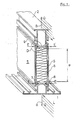
- the new composite profile which is used, for example, as a frame profile of a window, has two metal profile parts 1 and 2, preferably made of aluminum, for the necessary mechanical strength.
- plate-like webs 5 made of glass fiber reinforced polyamide are provided, between which 6 foam or mineral fiber material are additionally embedded as insulation material.
- the web connection can absorb transverse tensile forces Q, its ends are angled to anchoring strips 7, which are pressed into grooves 8 in the metal parts 1 and 2.
- the longitudinal shear forces L are also transmitted from the webs 5 to the metal parts 1 and 2 or vice versa in the composite area D.
- highly insulating metal-plastic composite profiles with a distance a between the metal parts 1 and 2 of at least 40 mm (EP-A1-01 17 885)
- there is a large difference in thermal expansion and due to the large temperature difference between the outer and inner profile parts 1 and 2 thus a large longitudinal shear stress on the plastic webs 5 and the composite zone D can also be expected.
- the direction of the two forces L and Q define the reference plane B, which runs parallel to the surfaces of the webs 5;
- the teeth 10 and the press-in direction E for the webs 5 and the strips 7 run perpendicular to this plane B into the grooves 8.
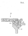
- a bending tab 9 is provided on the metal parts 1 and 2, which at the end of the press-in process for the anchoring strips 7 to be described in the grooves 8 against a rear shoulder 11 (FIG. 4) the last 7 is pressed.
- the tab 9 prevents the strips 7 from sliding out of the grooves 8; in practical use, it is not subjected to any loads.
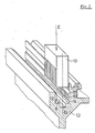
- the first step for the production of the new composite profile consists in cutting the toothing 10 into the side flanks 12 (FIG. 1) of the grooves 8 in the metal profile parts 1 and 2.
- the toothing 10 is cut in both side flanks 12 of the groove 8 by a hardened punch or reamer 13, for example made of steel, which penetrates into the groove 8 in the pressing direction E.
- a hardened punch or reamer 13 for example made of steel
- the undercut 14 in the groove 8 which on the one hand ensures that the metal chips peeled off by the punch 13 between the teeth 10 are torn off and second, these metal chips are "stored” until they are removed, e.g. blown out.
- 14 there is a rectangular depression 15, the function of which will be described later.
- longitudinal grooves 16 and 17 are provided for receiving the plastic of the webs 5 machined when pressed in, as will be described later.
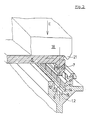
- Fig. 3 shows the beginning of the second operation in the manufacture of the composite, in which an anchoring strip 7 is pressed into the teeth 10 of the groove 8 by a press 18 in the same direction E as the teeth 10.
- the teeth 10 in the harder metal parts 1 and 2 cut a corresponding counter-toothing in the side flanks of the strips 7, the resulting chips being stored in collecting grooves 16 and 17 of the metal parts 1 and 2 and 19 and 20 at the foot of the anchoring strips 7.
- the plastic webs 5 can be pressed in at the same time in all four composite areas D - and advantageously over the entire profile length - with the aid of a correspondingly equipped press brake 18. will. Because of the material-related non-ideal cutting relationships between the strip 7 and the metal profile part 1 or 2, in addition to the machining deformation of the plastic, the legs 24, 25 (FIG. 4) of the groove 8 are also slightly expanded. The resulting preload in bond zone D ensures a secure positive and non-positive connection even in the event of large temperature fluctuations in practical use.
- a nose 21 on the outside of the press 18 bends the bending tab 9 in the direction of the web 5, this tab 9 resting on a shoulder 22 on the outer boundary of the web 5.
- the strip 7 engages in the aforementioned recess 15 in the bottom of the groove 8 of the metal profiles 1 and 2.
- the cam 23 clamps the anchoring strip 7 of the plastic web 5 in the metal profile 1 or 2 and thus absorbs the moment caused by the eccentric attack of the transverse tensile force Q in the strip 7.
- Lugs 23 and depression 15 thus prevent impermissible deformation of the plastic profile as a result of the eccentric attack of the transverse tensile forces Q.
Landscapes
- Civil Engineering (AREA)
- Structural Engineering (AREA)
- Engineering & Computer Science (AREA)
- Wing Frames And Configurations (AREA)
- Door And Window Frames Mounted To Openings (AREA)
- Moulding By Coating Moulds (AREA)
- Laminated Bodies (AREA)
- Thermal Insulation (AREA)
- Pens And Brushes (AREA)
- Adhesives Or Adhesive Processes (AREA)
- Compositions Of Macromolecular Compounds (AREA)
- Load-Bearing And Curtain Walls (AREA)
- Glass Compositions (AREA)
- Heating, Cooling, Or Curing Plastics Or The Like In General (AREA)
- Insulators (AREA)
- Insulating Bodies (AREA)
Abstract
Description
- Die Erfindung betrifft ein wärmedämmendes Verbundprofil für Fenster, Türen und/oder Fassaden, bei dem zwei Profilteile aus Metall durch Stege aus schlecht wärmeleitendem Kunststoff im Abstand voneinander gehalten sind, wobei die Kunststoffstege mit abgewinkelten Verankerungsleisten in Nuten der Metallteile eingreifen, und wobei ferner die Nuten mit einer verzahnungsähnlichen Struktur versehen sind.
- Verbundprofile der genannten Art sind beispielsweise aus der DE-C2-23 66 421 oder der EP-A- 01 23 110 bekannt; die in den Nuten angebrachte verzahnungsähnliche Struktur, die in einer eingeprägten Riffelung bzw. in eingepressten Einbuchtungen oder Zähnen besteht, dient dazu, die Schubfestigkeit in axialer Richtung zu verbessern. Die Verbindung der Stege, die zur Aufnahme der Querzugkräfte abgewinkelt sind, mit den Metallteilen wird dabei dadurch gewährleistet, dass die Isolierstege in Längsrichtung in hinterschnittene Nuten eingezogen sind und durch Anpressen einer Flanke des Metallteiles fixiert werden. Die zahnähnliche Struktur soll sich dabei in den Kunststoff einpressen, wobei dieser teils verdichtet und teils verdrängt wird.
- Aus Festigkeitsgründen werden die wärmeisolierenden Stege in neuerer Zeit aus faserverstärktem Kunststoff, insbesondere aus glasfaserverstärktem Polyamid, gefertigt. Es hat sich dabei gezeigt, dass ein Einprägen einer zahnähnlicher Struktur in faserverstärkten Kunststoff nur in ungenügendem Masse stattfindet, so dass die axiale Schubfestigkeit in unzulässiger Weise verringert wird und zu wenig zuverlässig ist. Bei bekannten Profilen hat man daher durch Hinzufügen von Zusatzelementen (siehe z. Beispiel EP-A- 00 85 410) und/oder mit Hilfe eines Klebstoffes (EP-A- 00 43 968) einen besseren Formschluss und eine höhere Schubfestigkeit angestrebt. Durch zusätzliche Arbeitsgänge für das Einbringen des Zusatzmaterials und/oder des Klebstoffes und für das Aushärten einer Klebeverbindung wird die Profilherstellung erheblich komplizierter und aufwendiger.
- Weiterhin müssen bisher die Kunststoffstege in Längsrichtung in die Metallteile eingezogen und anschliessend durch Anpressen einer Nutenflanke fixiert werden, da die Verbindung zwischen Metallteilen und Kunststoffstegen bei bisherigen Profilen dieser Art durch formschlüssiges Verbinden in hinterschnittenen Nuten erfolgt. Die Montage solcher Profile erfordert daher Anlagen, deren Länge mehr als das Zweifache der Profillänge beträgt; diese ist bei handelsüblichen Profilen etwa 6 m, so dass Montageplätze von etwa 15 m Länge erforderlich sind.
- Aufgabe der Erfindung ist es, den Verbund zwischen Metallteilen und faserverstärkten Stegen zu verbessern, insbesondere bei hochwärmegedämmten Verbundprofilen, bei denen an Festigkeit und Dauerhaftigkeit besonders hohe Anforderungen gestellt werden, da deren Stege eine 5- bis 8-fache Höhe derjenigen bisher üblicher Profile haben und infolge grösserer Temperaturdifferenzen höhere Schubbelastungen aufweisen. Weiterhin soll die Herstellung derartiger Verbundprofile vereinfacht werden, wobei vor allem der Platzbedarf und die Anzahl der Arbeitsgänge zu verringern sind.
- Diese Aufgabe wird dadurch gelöst, dass in seitliche Flanken der Nuten eine Verzahnung eingeschnitten ist, deren Zähne in Richtung senkrecht zur durch die Längsschub- und die Querzugkraft definierten Bezugsebene verlaufen, und dass ferner die Verankerungsleisten der aus faserverstärktem Kunststoff, insbesondere aus glasfaserverstärktem Polyamid, bestehenden Stege durch Einpressen in Richtung der Zähne mittels mindestens teilweise spanabhebender Formgebung in dem Kunststoff in die Verzahnung eingepasst und in ihr klebstofffrei verankert sind, ohne dass zur formschlüssigen Verbindung die Leisten Hinterschneidungen in den Nuten hintergreifen.
- Ein raum- und arbeitssparendes Herstellungsverfahren für die neuen Verbundprofile ist dadurch gekennzeichnet, dass mittels eines gehärteten Stempels oder Räumers in die seitlichen Flanken der Nuten der Metallteile die Verzahnung eingeschnitten wird, und dass anschliessend die Verankerungsleisten der Stege in Richtung senkrecht zur durch die Längsschub- und die Querzugkraft definierten Bezugsebene in die verzahnte Nut eingepresst werden.
- Die spanabhebende Formgebung, die durch die Verzahnung in dem faserverstärkten Kunststoff erfolgt, gewährleistet eine hohe Festigkeit des Verbundes und damit eine grosse Schubbelastbarkeit in axialer Richtung; das Fehlen von Hinterschneidungen für eine formschlüssige Verbindung erlaubt es den Verbund zwischen Metall und Kunststoff durch Einpressen in Richtung senkrecht zur durch Längsschub- und Querzugkraft definierten Ebene des Profils herzu stellen. Damit kann ein Einziehen der Stege in Längsrichtung des Profils entfallen. Der Platzbedarf für die Montage des Verbundprofils ist somit etwa auf die Profillänge, also auf etwas weniger als die Hälfte reduziert.
- Weiterhin findet durch das Einpressen wegen der materialbedingt nicht idealen Schnittverhältnisse zwischen faserverstärktem Kunststoff und dem Metallteil, der vorzugsweise aus Aluminium oder einer Aluminiumlegierung besteht, neben der zerspanenden Verformung des Kunststoffes ein leichts Aufspreizen der Metallschenkel der Nut statt; dadurch entsteht eine Vorspannung im Verbundbereich, die die Sicherheit des Form- und Kraftschlusses auch bei grossen Temperaturdifferenzen im praktischen Einsatz zusätzlich erhöht.
- Obwohl es generell möglich ist, die Nuten in gabelartigen abgewinkelten Flanken der Stege anzuordnen und die Verzahnung in Seitenflanken von entsprechenden Verankerungsleisten eines Metallteils anzubringen - also eine Umkehrung von "Vater"- und "Mutter"teil des Verbundes vorzunehmen -, ist es vorteilhaft, Nut und Verzahnung dem Metallteil zuzuordnen, weil wegen der Kaltfliesseigenschaften des Kunststoffes bei einer Zuordnung der Nuten zu dem Kunststoffsteg die geschilderte Vorspannung im Laufe der Zeit verlorenginge, und der Verbund beeinträchtigt werden könnte.
- Mit Vorteil kann als zusätzliche Sicherung des Verbundes ein Biegelappen vorgesehen sein.
- Durch die abgewinkelte Form der Verankerungsleisten an den Stegen wird die Querzugkraft aus den Stegen exzentrisch weitergeleitet; es ist daher zweckmässig, wenn an die Stirnseiten der Leisten ein in Längsrichtung verlaufender Nocken angesetzt ist, der in eine entsprechende Vertiefung der Nut eingreift. Der Nocken bewirkt durch den Eingriff in die Vertiefung eine Einspannung der abgewinkelten Verankerungsleiste in der Nut und verhindert eine unzulässige Deformation des Kunststoffsteges.
- Für die Herstellung des neuen Verbundprofils sind nur zwei Arbeitsgänge erforderlich: Das Schneiden der Verzahnung in den Metallteil und das spanabhebende Einpressen der Verzahnung in den Kunststoff. Darüber hinaus können diese beiden Arbeitsgänge mit Vorteil auf der ganzen Profilänge gleichzeitig durchgeführt werden.
- Die Material "verschiebenden" Schneid- und Einpressprozesse können erheblich erleichtert werden, wenn die Nut eine Hinterschneidung aufweist, die an die "inneren" Enden der Zähne anschliesst, und/ oder wenn am in Einpressrichtung hinteren Ende der Verzahnung die Nute und/oder die Leisten mit Auffangrillen für die Aufnahme der bei der Formgebung abgeschälten Kunststoffspäne versehen sind.
- Im folgenden wird die Erfindung anhand eines Ausführungsbeispiels im Zusammenhang mit der Zeichnung näher erläutert.
- Fig. 1 ist in schematischer räumlicher Darstellung ein Schnitt durch das neue Verbundprofil senkrecht zu siner Längsrichtung;
- Fig. 2 zeigt in ähnlicher räumlicher Darstellung das Schneiden der Verzahnung in eine Nut als ersten Arbeitsgang des Herstellungsverfahrens;
- Fig. 3 gibt den zweiten Arbeitsgang des Herstellungsverfahrens, nämlich das Einpressen des Kunststoffes in eine verzahnte Nut wieder;
- Fig. 4 schliesslich ist in ebener Darstellung eine Verbundstelle an dem neuen Profil als vergrössertes Detail D aus Fig. 1.
- Das neue Verbundprofil, das beispielsweise als Rahmenprofil eines Fensters dient, hat für die notwendige mechanische Festigkeit zwei metallene Profilteile 1 und 2, vorzugsweise aus Aluminium.
- Als wärmeisolierende Verbindung der Metallteile 1 und 2 sind plattenartige Stege 5 aus glasfaserverstärktem Polyamid vorgesehen, zwischen denen zusätzlich als Isolationsmaterial 6 Schaumstoff oder Mineralfasermaterial eingelagert sind.
- Damit die Stegverbindung Querzugkräfte Q aufnehmen kann, sind ihre Enden abgewinkelt zu Verankerungsleisten 7, die in Nuten 8 der Metallteile 1 und 2 eingepresst sind. Neben den Querzugkräften Q werden im Verbundbereich D auch die Längsschubkräfte L von den Stegen 5 auf die Metallteile 1 und 2 bzw. umgekehrt übertragen. Besonders bei hochisolierenden Metall-Kunststoff-Verbundprofilen mit einem Abstand a zwischen den Metallteilen 1 und 2 von mindestens 40 mm (EP-A1-01 17 885) ist wegen der grossen Temperaturdifferenz zwischen äusserem und inneren Profilteil 1 und 2 eine grosse Differenz der Wärmedehnung und somit auch eine grosse Längsschubbeanspruchung der Kunststoffstege 5 und der Verbundzone D zu erwarten.
- Die bei darartigen Verbundprofilen gestellten Mindestanforderungen hinsichtlich der notwendigen Widerstandsfähigkeit gegen Querzugkräfte Q sind beispielsweise in der "Richtlinie für den Nachweis der Standsicherheit von Metall-Kunststoff-Verbundprofilen" des Instituts für Bautechnik, Berlin, enthalten. Sie betragen für die Querzugkraft Q = 20 N/mm Profillänge bei einer Temperatur von 80°C
- Die Richtung der beiden Kräfte L und Q definieren die Bezugsebene B, die parallel den Flächen der Stege 5 verläuft; senkrecht zu dieser Ebene B verlaufen die Zähne 10 und die Einpressrichtung E für die Stege 5 bzw. die Leisten 7 in die Nuten 8.
- Als Sicherung des Verbundes zwischen den Profilteilen 1 und 2 und den Stegen 5 ist ein Biegelappen 9 an den Metallteilen 1 und 2 vorhanden, der am Ende des noch zu beschreibenden Einpressvorganges für die Verankerungsleisten 7 in die Nuten 8 gegen eine rückseitig Schulter 11 (Fig. 4) der Leisten 7 gepresst wird. Der Lappen 9 verhindert ein seitliches Herausgleiten der Leisten 7 aus den Nuten 8, im praktischen Einsatz ist er keinerlei Belastungen unterworfen.
- Der erste Schritt für die Herstellung des neuen Verbundprofils besteht im Schneiden der Verzahnung 10 in die Seitenflanken 12 (Fig. 1) der Nuten 8 in dem metallenen Profilteilen 1 und 2. Wie in der vergrösserten Darstellung einer Nut 8 in Fig. 2 gezeigt wird, wird die Verzahnung 10 in beiden Seitenflanken 12 der Nut 8 durch einen gehärteten Stempel oder Räumer 13, beispielsweise aus Stahl, eingeschnitten, der in Einpressrichtung E in die Nut 8 eindringt. An das "innere" Ende der Zähne 10 schliesst sich in der Nut 8 eine Hinterschneidung 14 an, die zum einen ein Abreissen der vom Stempel 13 zwischen den Zähnen 10 abgeschälten Metallspäne sicherge stellt und zum zweiten diese Metallspäne "eingelagert", bis sie entfernt, z.Beispiel ausgeblasen, werden. Im Boden der Nut 8,14 ist eine rechteckige Vertiefung 15, deren Funktion später beschrieben wird.
- Schliesslich sind "vor" den Zähnen 10 in den Seitenflanken 12 der Nut 8 Längsrillen 16 und 17 für die Aufnahme des beim Einpressen zerspanten Kunststoffs der Stege 5 vorgesehen, wie später noch beschrieben wird.
- Fig. 3 gibt den Beginn des zweiten Arbeitsganges bei der Herstellung des Verbundes wieder, bei dem eine Verankerungsleiste 7 in die Verzahnung 10 der Nut 8 von einer Presse 18 in der gleichen Richtung E wie die Verzahnung 10 eingepresst werden. Die Zähne 10 in den härteren Metallteilen 1 und 2 schneiden dabei eine entsprechende Gegenverzahnung in die Seitenflanken der Leisten 7, wobei die anfallenden Späne in Auffangrillen 16 und 17 der Metallteile 1 und 2 und 19 und 20 am Fuss der Verankerungsleisten 7 eingelagert werden.
- Die Kunststoffstege 5 können dabei in allen vier Verbundbereichen D - und mit Vorteil über die gesamte Profillänge - mit Hilfe einer entsprechend ausgerüsteten Abkantpresse 18 gleichzeitig eingepresst. werden. Wegen der materialbedingt nicht idealen Schnittverhältnisse zwischen der Leiste 7 und dem metallenen Profilteil 1 oder 2 findet neben der zerspanenden Verformung des Kunststoffs auch ein leichtes Aufspreizen der Schenkel 24,25 (Fig. 4) der Nut 8 statt. Die dadurch entstehende Vorspannung in der Verbundzone D gewährleistet einen sicheren Form- und Kraftschluss auch bei grossen Temperaturschwankungen im praktischen Einsatz.
- Gegen Ende des Einpressvorgangs biegt eine Nase 21 an der Aussenseite der Presse 18 den Biegelappen 9 in Richtung auf den Steg 5, wobei dieser Lappen 9 auf einer Schulter 22 an der äusseren Begrenzung des Steges 5 zur Auflage kommt.
- Mit einem stirnseitigen Nocken 23 greift die Leiste 7 in die bereits erwähnte Vertiefung 15 im Boden der Nut 8 der Metallprofile 1 und 2 ein. Durch diesen Eingriff bewirkt der Nocken 23 eine Einspannung der Verankerungsleiste 7 des Kunststoffsteges 5 im Metallprofil 1 oder 2 und nimmt so das Moment auf, das durch den exzentrischen Angriff der Querzugkraft Q in der Leiste 7 entsteht. Nokken 23 und Vertiefung 15 verhindern so eine unzulässige Deformation des Kunststoffprofiles infolge des exzentrischen Angreifens der Querzugkräfte Q.
- Wie bereits erwähnt ist es auch möglich, die Erfindung bei einer Umkehrung von Nut und Leiste anzwenden, wobei die Leiste am Metallprofil 1 oder 2 und die Nut am Steg 5 angeordnet sind, was jedoch wegen des Kaltfliessens des Kunststoffes gewisse Nachteile mit sich bringt.
Claims (7)
Priority Applications (9)
| Application Number | Priority Date | Filing Date | Title |
|---|---|---|---|
| DE8686810095T DE3666259D1 (en) | 1986-02-25 | 1986-02-25 | Thermally insulating composite profile member |
| AT86810095T ATE47193T1 (de) | 1986-02-25 | 1986-02-25 | Waermedaemmendes verbundprofil. |
| EP86810095A EP0235493B1 (de) | 1986-02-25 | 1986-02-25 | Wärmedämmendes Verbundprofil |
| DK007087A DK165992C (da) | 1986-02-25 | 1987-01-07 | Varmeisolerende, sammensat profil og fremgangsmaade til fremstilling af det sammensatte profil |
| FI870195A FI83254C (fi) | 1986-02-25 | 1987-01-19 | Vaermeisolerande lamellprofil och foerfarande foer dess tillverkning. |
| US07/015,289 US4786539A (en) | 1986-02-25 | 1987-02-17 | Thermal insulating composite laminate |
| NO870753A NO166668C (no) | 1986-02-25 | 1987-02-24 | Varmeisolerende, sammensatt profil, og fremgangsmaate ved fremstilling av samme. |
| JP62041219A JPH0730657B2 (ja) | 1986-02-25 | 1987-02-24 | 断熱作用を有する型抜き材枠構造及びその製作方法 |
| CA000530437A CA1286471C (en) | 1986-02-25 | 1987-02-24 | Thermal insulating composite laminate |
Applications Claiming Priority (1)
| Application Number | Priority Date | Filing Date | Title |
|---|---|---|---|
| EP86810095A EP0235493B1 (de) | 1986-02-25 | 1986-02-25 | Wärmedämmendes Verbundprofil |
Publications (2)
| Publication Number | Publication Date |
|---|---|
| EP0235493A1 true EP0235493A1 (de) | 1987-09-09 |
| EP0235493B1 EP0235493B1 (de) | 1989-10-11 |
Family
ID=8196453
Family Applications (1)
| Application Number | Title | Priority Date | Filing Date |
|---|---|---|---|
| EP86810095A Expired EP0235493B1 (de) | 1986-02-25 | 1986-02-25 | Wärmedämmendes Verbundprofil |
Country Status (9)
| Country | Link |
|---|---|
| US (1) | US4786539A (de) |
| EP (1) | EP0235493B1 (de) |
| JP (1) | JPH0730657B2 (de) |
| AT (1) | ATE47193T1 (de) |
| CA (1) | CA1286471C (de) |
| DE (1) | DE3666259D1 (de) |
| DK (1) | DK165992C (de) |
| FI (1) | FI83254C (de) |
| NO (1) | NO166668C (de) |
Cited By (1)
| Publication number | Priority date | Publication date | Assignee | Title |
|---|---|---|---|---|
| FR2922990A1 (fr) * | 2007-10-31 | 2009-05-01 | Norsk Hydro As | Barre isolante, de type profile, destinee a etre associee a une barre metallique, de type profile, par une liaison complete, et barre de construction ainsi obtenue |
Families Citing this family (8)
| Publication number | Priority date | Publication date | Assignee | Title |
|---|---|---|---|---|
| US4892770A (en) * | 1988-08-10 | 1990-01-09 | Davidson Textron Inc. | Interior trim foam product and method of fabrication thereof |
| US5469683A (en) * | 1994-02-09 | 1995-11-28 | Kawneer Company, Inc. | Thermally insulating composite frame member with snap-in thermal isolator |
| US8617702B2 (en) | 2010-04-28 | 2013-12-31 | Sabic Innovative Plastics Ip B.V. | Thermally insulated structural members, and doors and windows incorporating them |
| US9133614B2 (en) * | 2011-11-14 | 2015-09-15 | Oldcastle Buildingenvelope, Inc. | Method and system for thermal barrier installation |
| WO2015006847A1 (en) | 2013-07-19 | 2015-01-22 | Litezone Technologies Inc. | Pressure compensated glass unit |
| US10125537B2 (en) * | 2014-07-18 | 2018-11-13 | Litezone Technologies Inc. | Pressure compensated glass unit |
| EP3396096B1 (de) * | 2017-04-28 | 2020-02-19 | RP Technik GmbH Profilsysteme | Verbundprofil sowie verfahren zur herstellung des verbundprofils |
| US10370893B2 (en) * | 2017-09-15 | 2019-08-06 | Arconic Inc. | Apparatus and method for assembly of structural profiles and resultant structures |
Citations (5)
| Publication number | Priority date | Publication date | Assignee | Title |
|---|---|---|---|---|
| FR2312615A1 (fr) * | 1975-05-27 | 1976-12-24 | Capitol Prod Corp | Profile isolant et son application pour la realisation d'un element de construction calorifuge |
| DE2741905A1 (de) * | 1977-09-17 | 1979-03-22 | Volkmar Heuser | Waermeisolierender rahmenschenkel fuer fenster, tueren o.dgl. |
| DE2744553A1 (de) * | 1977-10-04 | 1979-04-05 | Hartmann & Co W | Verfahren zur herstellung von verbundprofilstaeben und hierzu verwendetes stegprofil |
| EP0032408A2 (de) * | 1978-03-20 | 1981-07-22 | Helmar Dr. Dr. Nahr | Wärmeisolierender Profilkörper |
| EP0059458A1 (de) * | 1981-02-27 | 1982-09-08 | Tefo Ag | Verbindungsanordnung |
Family Cites Families (2)
| Publication number | Priority date | Publication date | Assignee | Title |
|---|---|---|---|---|
| DE2904192C2 (de) * | 1979-02-05 | 1982-03-25 | Fa. Eduard Hueck, 5880 Lüdenscheid | Verfahren zur Herstellung eines Verbundprofils für Fensterrahmen, Türrahmen, Fassadenkonstruktionen o.dgl. |
| JPS5758676U (de) * | 1980-09-25 | 1982-04-06 |
-
1986
- 1986-02-25 AT AT86810095T patent/ATE47193T1/de active
- 1986-02-25 DE DE8686810095T patent/DE3666259D1/de not_active Expired
- 1986-02-25 EP EP86810095A patent/EP0235493B1/de not_active Expired
-
1987
- 1987-01-07 DK DK007087A patent/DK165992C/da not_active IP Right Cessation
- 1987-01-19 FI FI870195A patent/FI83254C/fi not_active IP Right Cessation
- 1987-02-17 US US07/015,289 patent/US4786539A/en not_active Expired - Lifetime
- 1987-02-24 CA CA000530437A patent/CA1286471C/en not_active Expired - Lifetime
- 1987-02-24 JP JP62041219A patent/JPH0730657B2/ja not_active Expired - Lifetime
- 1987-02-24 NO NO870753A patent/NO166668C/no unknown
Patent Citations (5)
| Publication number | Priority date | Publication date | Assignee | Title |
|---|---|---|---|---|
| FR2312615A1 (fr) * | 1975-05-27 | 1976-12-24 | Capitol Prod Corp | Profile isolant et son application pour la realisation d'un element de construction calorifuge |
| DE2741905A1 (de) * | 1977-09-17 | 1979-03-22 | Volkmar Heuser | Waermeisolierender rahmenschenkel fuer fenster, tueren o.dgl. |
| DE2744553A1 (de) * | 1977-10-04 | 1979-04-05 | Hartmann & Co W | Verfahren zur herstellung von verbundprofilstaeben und hierzu verwendetes stegprofil |
| EP0032408A2 (de) * | 1978-03-20 | 1981-07-22 | Helmar Dr. Dr. Nahr | Wärmeisolierender Profilkörper |
| EP0059458A1 (de) * | 1981-02-27 | 1982-09-08 | Tefo Ag | Verbindungsanordnung |
Cited By (3)
| Publication number | Priority date | Publication date | Assignee | Title |
|---|---|---|---|---|
| FR2922990A1 (fr) * | 2007-10-31 | 2009-05-01 | Norsk Hydro As | Barre isolante, de type profile, destinee a etre associee a une barre metallique, de type profile, par une liaison complete, et barre de construction ainsi obtenue |
| EP2055883A2 (de) | 2007-10-31 | 2009-05-06 | Norsk Hydro ASA | Verfahren zur Herstellung einer Baustrebe durch Crimpen, und so erhaltene Baustrebe |
| EP2055883A3 (de) * | 2007-10-31 | 2011-01-19 | Norsk Hydro ASA | Verfahren zur Herstellung einer Baustrebe durch Crimpen, und so erhaltene Baustrebe |
Also Published As
| Publication number | Publication date |
|---|---|
| NO166668B (no) | 1991-05-13 |
| EP0235493B1 (de) | 1989-10-11 |
| NO870753D0 (no) | 1987-02-24 |
| CA1286471C (en) | 1991-07-23 |
| FI83254C (fi) | 1991-06-10 |
| DK7087A (da) | 1987-08-26 |
| NO870753L (no) | 1987-08-26 |
| FI83254B (fi) | 1991-02-28 |
| NO166668C (no) | 1991-08-21 |
| DK165992C (da) | 1993-07-05 |
| DK165992B (da) | 1993-02-22 |
| US4786539A (en) | 1988-11-22 |
| FI870195A (fi) | 1987-08-26 |
| JPS62202186A (ja) | 1987-09-05 |
| DK7087D0 (da) | 1987-01-07 |
| FI870195A0 (fi) | 1987-01-19 |
| DE3666259D1 (en) | 1989-11-16 |
| JPH0730657B2 (ja) | 1995-04-10 |
| ATE47193T1 (de) | 1989-10-15 |
Similar Documents
| Publication | Publication Date | Title |
|---|---|---|
| EP2476853B1 (de) | Verbundprofil für Fenster, Türen und Fassaden sowie Verfahren zu dessen Herstellung | |
| EP1555376A1 (de) | Verbundprofilanordnung | |
| EP1024243A2 (de) | Brandsichere Isolierstegverbindung | |
| DE10326503A1 (de) | Aluminium-Verbundprofil für Fenster- oder Türrahmen | |
| EP0235493B1 (de) | Wärmedämmendes Verbundprofil | |
| EP1138864B1 (de) | Verbundprofil für Fenster, Fassaden, Türen oder Lichtdächer | |
| EP0551836B1 (de) | Schraubverbindung zwischen einer Profilschiene und einem Beschlag oder einem sonstigen Bauteil | |
| EP0043968B1 (de) | Verbundprofil, insbesondere für Fenster, Türen od. dgl. | |
| EP0261159B1 (de) | Verbundprofil | |
| DE3101630C2 (de) | Verbindung von formstabilen Elementen | |
| EP2325431B1 (de) | Verfahren zur Herstellung eines wärmegedämmten Verbundprofils | |
| DE7511558U (de) | Waermeisoliertes aluminiumprofil fuer aussenwandkonstruktionen | |
| DE3702004C2 (de) | ||
| EP0952270B2 (de) | Tragprofile für Riegel-Pfosten-Fassaden, Vordächer, Galerien o. dgl. | |
| DE19828188C1 (de) | Fassadenprofil | |
| DE2826783C2 (de) | Verbundprofil, insbesondere für Fenster, Türen o.dgl. | |
| DE2821096C2 (de) | ||
| EP1215360B9 (de) | Verbundprofil | |
| EP1837095A2 (de) | Metallprofil für Rahmenkonstruktionen von Fenster-, Tür- oder Fassadenelementen sowie Verfahren zur Herstellung desselben | |
| EP1199481A1 (de) | Querverbindung von Profilstäben | |
| EP0748919A2 (de) | T-Verbinder für eine aus Metall gefertigte Aussenschale eines wärmegedämmten Rahmenprofils für Fenster, Türen oder Fassaden | |
| DE102020106891B4 (de) | T-Verbindung zwischen einem Pfosten- und Riegelprofil und Pfosten-Riegel-Konstruktion mit einer derartigen T-Verbindung | |
| EP1698736B1 (de) | Fassade und Verfahren zur Herstellung einer Fassade | |
| DE19740461C2 (de) | Verfahren und Verbindungssystem zur unlösbaren Verbindung von Profilen oder Profilelementen | |
| EP0540982A1 (de) | Eckverbinder für Hohlprofile eines Fensters, einer Tür, einer Fassade od.dgl. |
Legal Events
| Date | Code | Title | Description |
|---|---|---|---|
| PUAI | Public reference made under article 153(3) epc to a published international application that has entered the european phase |
Free format text: ORIGINAL CODE: 0009012 |
|
| AK | Designated contracting states |
Kind code of ref document: A1 Designated state(s): AT BE CH DE FR GB IT LI LU NL SE |
|
| RBV | Designated contracting states (corrected) |
Designated state(s): AT BE CH DE FR GB IT LI NL SE |
|
| 17P | Request for examination filed |
Effective date: 19880119 |
|
| 17Q | First examination report despatched |
Effective date: 19880819 |
|
| GRAA | (expected) grant |
Free format text: ORIGINAL CODE: 0009210 |
|
| AK | Designated contracting states |
Kind code of ref document: B1 Designated state(s): AT BE CH DE FR GB IT LI NL SE |
|
| REF | Corresponds to: |
Ref document number: 47193 Country of ref document: AT Date of ref document: 19891015 Kind code of ref document: T |
|
| ITF | It: translation for a ep patent filed |
Owner name: ING. ZINI MARANESI & C. S.R.L. |
|
| GBT | Gb: translation of ep patent filed (gb section 77(6)(a)/1977) | ||
| REF | Corresponds to: |
Ref document number: 3666259 Country of ref document: DE Date of ref document: 19891116 |
|
| ET | Fr: translation filed | ||
| PLBE | No opposition filed within time limit |
Free format text: ORIGINAL CODE: 0009261 |
|
| STAA | Information on the status of an ep patent application or granted ep patent |
Free format text: STATUS: NO OPPOSITION FILED WITHIN TIME LIMIT |
|
| 26N | No opposition filed | ||
| ITTA | It: last paid annual fee | ||
| PGFP | Annual fee paid to national office [announced via postgrant information from national office to epo] |
Ref country code: FR Payment date: 19950113 Year of fee payment: 10 |
|
| PGFP | Annual fee paid to national office [announced via postgrant information from national office to epo] |
Ref country code: SE Payment date: 19950116 Year of fee payment: 10 Ref country code: AT Payment date: 19950116 Year of fee payment: 10 |
|
| PGFP | Annual fee paid to national office [announced via postgrant information from national office to epo] |
Ref country code: GB Payment date: 19950119 Year of fee payment: 10 Ref country code: DE Payment date: 19950119 Year of fee payment: 10 |
|
| PGFP | Annual fee paid to national office [announced via postgrant information from national office to epo] |
Ref country code: BE Payment date: 19950126 Year of fee payment: 10 |
|
| EAL | Se: european patent in force in sweden |
Ref document number: 86810095.9 |
|
| PGFP | Annual fee paid to national office [announced via postgrant information from national office to epo] |
Ref country code: CH Payment date: 19950223 Year of fee payment: 10 |
|
| PGFP | Annual fee paid to national office [announced via postgrant information from national office to epo] |
Ref country code: NL Payment date: 19950228 Year of fee payment: 10 |
|
| PG25 | Lapsed in a contracting state [announced via postgrant information from national office to epo] |
Ref country code: GB Effective date: 19960225 Ref country code: AT Effective date: 19960225 |
|
| PG25 | Lapsed in a contracting state [announced via postgrant information from national office to epo] |
Ref country code: SE Effective date: 19960226 |
|
| PG25 | Lapsed in a contracting state [announced via postgrant information from national office to epo] |
Ref country code: LI Free format text: LAPSE BECAUSE OF NON-PAYMENT OF DUE FEES Effective date: 19960228 Ref country code: CH Free format text: LAPSE BECAUSE OF NON-PAYMENT OF DUE FEES Effective date: 19960228 Ref country code: BE Effective date: 19960228 |
|
| BERE | Be: lapsed |
Owner name: GEILINGER A.G. Effective date: 19960228 |
|
| PG25 | Lapsed in a contracting state [announced via postgrant information from national office to epo] |
Ref country code: NL Effective date: 19960901 |
|
| REG | Reference to a national code |
Ref country code: CH Ref legal event code: PL |
|
| GBPC | Gb: european patent ceased through non-payment of renewal fee |
Effective date: 19960225 |
|
| PG25 | Lapsed in a contracting state [announced via postgrant information from national office to epo] |
Ref country code: FR Effective date: 19961031 |
|
| NLV4 | Nl: lapsed or anulled due to non-payment of the annual fee |
Effective date: 19960901 |
|
| PG25 | Lapsed in a contracting state [announced via postgrant information from national office to epo] |
Ref country code: DE Effective date: 19961101 |
|
| REG | Reference to a national code |
Ref country code: FR Ref legal event code: ST |
|
| PG25 | Lapsed in a contracting state [announced via postgrant information from national office to epo] |
Ref country code: IT Free format text: LAPSE BECAUSE OF NON-PAYMENT OF DUE FEES;WARNING: LAPSES OF ITALIAN PATENTS WITH EFFECTIVE DATE BEFORE 2007 MAY HAVE OCCURRED AT ANY TIME BEFORE 2007. THE CORRECT EFFECTIVE DATE MAY BE DIFFERENT FROM THE ONE RECORDED. Effective date: 20050225 |