EP0231498B1 - Ferrure pour panneau de fenêtre, porte ou similaire pouvant au moins être basculé - Google Patents
Ferrure pour panneau de fenêtre, porte ou similaire pouvant au moins être basculé Download PDFInfo
- Publication number
- EP0231498B1 EP0231498B1 EP86117491A EP86117491A EP0231498B1 EP 0231498 B1 EP0231498 B1 EP 0231498B1 EP 86117491 A EP86117491 A EP 86117491A EP 86117491 A EP86117491 A EP 86117491A EP 0231498 B1 EP0231498 B1 EP 0231498B1
- Authority
- EP
- European Patent Office
- Prior art keywords
- leaf
- stays
- wing
- link
- fitting according
- Prior art date
- Legal status (The legal status is an assumption and is not a legal conclusion. Google has not performed a legal analysis and makes no representation as to the accuracy of the status listed.)
- Expired
Links
- 238000013459 approach Methods 0.000 description 1
- 238000004140 cleaning Methods 0.000 description 1
- 238000010276 construction Methods 0.000 description 1
- 230000008878 coupling Effects 0.000 description 1
- 238000010168 coupling process Methods 0.000 description 1
- 238000005859 coupling reaction Methods 0.000 description 1
- 238000004519 manufacturing process Methods 0.000 description 1
- 239000000463 material Substances 0.000 description 1
Images

Classifications
-
- E—FIXED CONSTRUCTIONS
- E05—LOCKS; KEYS; WINDOW OR DOOR FITTINGS; SAFES
- E05D—HINGES OR SUSPENSION DEVICES FOR DOORS, WINDOWS OR WINGS
- E05D15/00—Suspension arrangements for wings
- E05D15/06—Suspension arrangements for wings for wings sliding horizontally more or less in their own plane
- E05D15/10—Suspension arrangements for wings for wings sliding horizontally more or less in their own plane movable out of one plane into a second parallel plane
- E05D15/1005—Suspension arrangements for wings for wings sliding horizontally more or less in their own plane movable out of one plane into a second parallel plane the wing being supported on arms movable in horizontal planes
- E05D15/1013—Suspension arrangements for wings for wings sliding horizontally more or less in their own plane movable out of one plane into a second parallel plane the wing being supported on arms movable in horizontal planes specially adapted for windows
- E05D15/1015—Suspension arrangements for wings for wings sliding horizontally more or less in their own plane movable out of one plane into a second parallel plane the wing being supported on arms movable in horizontal planes specially adapted for windows with an intermediate tilt position
-
- E—FIXED CONSTRUCTIONS
- E05—LOCKS; KEYS; WINDOW OR DOOR FITTINGS; SAFES
- E05C—BOLTS OR FASTENING DEVICES FOR WINGS, SPECIALLY FOR DOORS OR WINDOWS
- E05C17/00—Devices for holding wings open; Devices for limiting opening of wings or for holding wings open by a movable member extending between frame and wing; Braking devices, stops or buffers, combined therewith
- E05C17/02—Devices for holding wings open; Devices for limiting opening of wings or for holding wings open by a movable member extending between frame and wing; Braking devices, stops or buffers, combined therewith by mechanical means
- E05C17/04—Devices for holding wings open; Devices for limiting opening of wings or for holding wings open by a movable member extending between frame and wing; Braking devices, stops or buffers, combined therewith by mechanical means with a movable bar or equivalent member extending between frame and wing
- E05C17/12—Devices for holding wings open; Devices for limiting opening of wings or for holding wings open by a movable member extending between frame and wing; Braking devices, stops or buffers, combined therewith by mechanical means with a movable bar or equivalent member extending between frame and wing consisting of a single rod
- E05C17/24—Devices for holding wings open; Devices for limiting opening of wings or for holding wings open by a movable member extending between frame and wing; Braking devices, stops or buffers, combined therewith by mechanical means with a movable bar or equivalent member extending between frame and wing consisting of a single rod pivoted at one end, and with the other end running along a guide member
- E05C17/26—Devices for holding wings open; Devices for limiting opening of wings or for holding wings open by a movable member extending between frame and wing; Braking devices, stops or buffers, combined therewith by mechanical means with a movable bar or equivalent member extending between frame and wing consisting of a single rod pivoted at one end, and with the other end running along a guide member with braking, clamping or securing means at the pivot of the rod
-
- E—FIXED CONSTRUCTIONS
- E05—LOCKS; KEYS; WINDOW OR DOOR FITTINGS; SAFES
- E05D—HINGES OR SUSPENSION DEVICES FOR DOORS, WINDOWS OR WINGS
- E05D15/00—Suspension arrangements for wings
- E05D15/06—Suspension arrangements for wings for wings sliding horizontally more or less in their own plane
- E05D15/10—Suspension arrangements for wings for wings sliding horizontally more or less in their own plane movable out of one plane into a second parallel plane
- E05D2015/1028—Suspension arrangements for wings for wings sliding horizontally more or less in their own plane movable out of one plane into a second parallel plane with only the wing moving transversely
- E05D2015/1031—Suspension arrangements for wings for wings sliding horizontally more or less in their own plane movable out of one plane into a second parallel plane with only the wing moving transversely the wing supported on arms extending from the carriage
-
- E—FIXED CONSTRUCTIONS
- E05—LOCKS; KEYS; WINDOW OR DOOR FITTINGS; SAFES
- E05Y—INDEXING SCHEME ASSOCIATED WITH SUBCLASSES E05D AND E05F, RELATING TO CONSTRUCTION ELEMENTS, ELECTRIC CONTROL, POWER SUPPLY, POWER SIGNAL OR TRANSMISSION, USER INTERFACES, MOUNTING OR COUPLING, DETAILS, ACCESSORIES, AUXILIARY OPERATIONS NOT OTHERWISE PROVIDED FOR, APPLICATION THEREOF
- E05Y2201/00—Constructional elements; Accessories therefor
- E05Y2201/60—Suspension or transmission members; Accessories therefor
- E05Y2201/606—Accessories therefor
- E05Y2201/62—Synchronisation of suspension or transmission members
-
- E—FIXED CONSTRUCTIONS
- E05—LOCKS; KEYS; WINDOW OR DOOR FITTINGS; SAFES
- E05Y—INDEXING SCHEME ASSOCIATED WITH SUBCLASSES E05D AND E05F, RELATING TO CONSTRUCTION ELEMENTS, ELECTRIC CONTROL, POWER SUPPLY, POWER SIGNAL OR TRANSMISSION, USER INTERFACES, MOUNTING OR COUPLING, DETAILS, ACCESSORIES, AUXILIARY OPERATIONS NOT OTHERWISE PROVIDED FOR, APPLICATION THEREOF
- E05Y2201/00—Constructional elements; Accessories therefor
- E05Y2201/60—Suspension or transmission members; Accessories therefor
- E05Y2201/622—Suspension or transmission members elements
- E05Y2201/686—Rods, links
-
- E—FIXED CONSTRUCTIONS
- E05—LOCKS; KEYS; WINDOW OR DOOR FITTINGS; SAFES
- E05Y—INDEXING SCHEME ASSOCIATED WITH SUBCLASSES E05D AND E05F, RELATING TO CONSTRUCTION ELEMENTS, ELECTRIC CONTROL, POWER SUPPLY, POWER SIGNAL OR TRANSMISSION, USER INTERFACES, MOUNTING OR COUPLING, DETAILS, ACCESSORIES, AUXILIARY OPERATIONS NOT OTHERWISE PROVIDED FOR, APPLICATION THEREOF
- E05Y2900/00—Application of doors, windows, wings or fittings thereof
- E05Y2900/10—Application of doors, windows, wings or fittings thereof for buildings or parts thereof
- E05Y2900/13—Type of wing
- E05Y2900/148—Windows
Definitions
- the invention relates to a fitting for an at least tiltable sash of a window, a door or the like, the upper wing end being connected to a fixed frame or the like via two extending arms which are arranged at a lateral distance and are at least rotatably mounted on both ends, and the like two extension arms are coupled together by means of a handlebar.
- the latter results in a forced parallel guidance of the assigned upper wing end, which, when the tilted wing is closed, is intended to ensure that the upper wing cross member approaches the parallel cross member of the fixed frame or the like as parallel as possible.
- Such positively controlled constructions are used in particular in the case of simpler fittings, in which the sash is moved into the tilted position or unlocked from the tilted position into the closed position after unlocking with the twist grip of the lock. If the parallel position of the above bars is not guaranteed, the upper wing corner removed from the operating handle does not run in properly or it jams in the fold. This can lead to the closure closing.
- the two extension arms are articulated on the frame side on so-called sliders, which ensure that the tilted or parallel-parked sash is pushed sideways.
- the two extension arms are coupled there on the frame side by connecting the two sliders.
- the parallelogram formed by the hinging axes of the two extension arms on the frame side and the two pivoting axes of the handlebars on the gliders runs extremely flat in the closing-end movement of the sash. Because there must always be a certain amount of play with fittings and this also applies to the bearing points, with this known fitting shortly before reaching the closed position, perfect parallel guidance is no longer guaranteed. As a result, so-called pre-closing with this fitting, in particular with wide sashes, cannot be ruled out.
- the object of the invention is therefore to further develop a fitting of the type mentioned in such a way that, even with the usual tolerances, perfect parallel guidance is ensured up to the closed position of the sash, but also in the opposite direction, and so-called pre-closing is prevented.
- the fitting is designed according to the preamble of claim 1 in accordance with the characterizing part of this claim.
- the effort with this fitting is not greater than with the known one, but the flat parallelogram can now be avoided, especially shortly before the closing end position is reached.
- wide sashes are also perfectly parallel up to the closing position.
- the handlebar is in this solution in front of the so-called wing flap, but this is insignificant insofar as with such fittings the extension arms are mounted on the flap anyway and they are normally covered by a profile that extends across the entire wing width. The latter then also covers the handlebar. Accordingly, there is no disadvantage in terms of effort or aesthetic impression in this direction.
- a further development of the invention provides that the two wing-side axes of rotation of the extension arms and the axes of rotation of the handlebar form a parallelogram with approximately right angles when the wing is closed.
- the exact right-angled position of this imaginary parallelogram is deliberately avoided for the usual reasons, however, the short parallelogram pages run through the right-angled position during the opening movement, in order then to assume an inclined position towards the other side during the further opening movement.
- each extension arm is widened at its wing-side end, in particular having a lateral bearing eye for the articulation axis of the handlebar.
- the size of the bearing eye depends on the width of the extension arm, measured transversely to the plane of the wing, and it also depends on the thickness of the spar. The bearing eye or the widening must ensure that the handlebar-side axis comes to lie in front of the wing plane, because the handlebar, as I said, is in front of the space-facing surface of the assigned wing cross member.
- Another variant of the invention is characterized by a latching device for each extension arm which is effective at least in the opening position of the opening arm.
- the latching device should automatically come into operation in order to prevent the relevant extension arms from pivoting back and thus preventing the undesired closing movement.
- the latching device can also be designed in such a way that it secures both the closed position and the open position.
- the locking device consists of a locking element, in particular a locking lug of the opening arm, and a locking element on the wing.
- the latching element is expediently made of plastic, the aim being to achieve a resilient behavior of the latching element, in particular by appropriate choice of material and shape and dimensioning.
- the locking member or the locking lug is automatically moved in the direction of the locking of the locking element and then occurs in the pivoting end ge of the extension arms and possibly also in the closed position of the latter automatically into the locking recess of the locking element.
- two locking receptacles are then available, with which the locking lug engages in the assigned pivoting end position of the relevant extension arm.
- the design can be such that, on the one hand, a moment in the closing direction becomes effective from a predetermined position of the assigned raising arm and a moment in the opening direction when the sash is opened.
- the latching element can expediently be latched against the force of a load spring and is therefore particularly effective.
- a preferred variant of such a fitting with an additional wing that can be parked in parallel is characterized in that the two extension arms of the lower wing end are connected by means of a handlebar.
- the articulation of the upper and lower arm pairs on the sash and frame takes place in an identical manner and this also applies to the coupling of the two arm ends on the wing side by means of an upper and a lower link.
- the lower extension arms are not hinged to so-called scissor gliders or comparable elements, but to a lower carriage.
- the wing is not only tiltable, but can also be set down in parallel and, in a particularly preferred manner, it can be pushed sideways in front of a fixed field or a second wing, in particular a so-called cleaning wing, when using scissor gliders and carriages, at least in the parallel storage position.
- the wing can either be tilted or folded or, with the simultaneous pivoting of all four extension arms, can also be parked directly in parallel after unlocking.
- closing the wing In any case, however, it is ensured that the upper and lower wing spars are each moved exactly parallel to the corresponding spars of the fixed frame or the like, to the closed position or to the full open position.
- extension arms In the case of a wing which is held on four raising arms and can be parked in parallel, locking is reliably prevented with only a handlebar on only the upper raising arms.
- the relative rotation of the extension arms relative to their handlebars takes place via corresponding axes of rotation, which are held in a rotationally fixed manner either on the handlebars or on the extension arm. If you provide the non-rotatable connection on the handlebar, only a simple storage is required on the extension arm.
- the extension arms can therefore be used with a fitting with and without a handlebar. This is very useful for large series production.
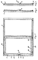
- a wing 2 can be tilted (FIG. 2) and set down in parallel (FIG. 3), and in the parallel storage position it is slidably mounted in front of a second wing 3.
- the transfer from the unlocked closed position (FIG. 1) into the tilted position and the parallel storage position is preferably carried out by pulling on the handle 4, which can be rotated in a gear mechanism 5, the rotary movement serving for locking and unlocking in a known manner and being transmitted to connecting rods 6 becomes.
- So-called corner deflections 7, which are located on all four wing corners in the exemplary embodiment, transmit the vertical movement of the drive rods 6 or drive rod halves to further horizontal drive rods. Latches are actuated via the latter, which interact with striking plates on the fixed frame.
- the locking members move in their striking plates or the like and one can then subsequently pull on Move the handle towards the interior of the wing into a tilted position and then into a parallel storage position or immediately into the latter. Accordingly, the wing placed in parallel is either first brought back into the tilted position and then into the closed position by acting on the handle 4 in the direction of arrow 9 or else directly on the wing. Turning the handle 4 against the arrow 8 then causes the locking with the fixed frame.
- each horizontal wing cross member is connected to the fixed frame 1 both at its upper and at its lower end by means of an upper extension arm pair 10 and a lower extension arm pair 11.
- Each pair consists of a first opening arm 12 on the lock side and a second opening arm 13 parallel to it.
- the first opening arm 12 is rotatably mounted on the wing about an axis 14 and on the fixed frame about an axis 15 parallel to it.
- the corresponding axes of each second extension arm 13 are designated 16 and 17.
- the support arms 12 and 13 are mounted on the frame on the upper cross member 18 of the fixed frame 1 on so-called scissor sliders 19 and 20, which are displaceably mounted in a running rail 21 in the sense of the double arrow 22.
- scissor sliders 19 and 20 which are displaceably mounted in a running rail 21 in the sense of the double arrow 22.
- each wing-side bearing axis 14 or 16 there is a bearing pin 26 or 27 running parallel to it. It connects the relevant end of the extension arm with the associated end of a link 28. This extends parallel to the associated cross member 18 or 29. Each link 28 is located in front of the cross member towards the interior of the room and runs parallel to it.
- the bearing bolts 26 and 27 are rotatably mounted either in the extension arm or in the handlebar. If they are secured against falling out, they can advantageously be rotatably supported in both elements.
- the two axes 14 and 16 and the two axes 26 and 27 mark the corners of an imaginary parallelogram. 5, the relative position of the axis 26 to the axis 14 is indicated with the wing 2 closed with a dashed circle 38. It can be seen that the corners of the parallelogram come very close to a right angle in both rotational end positions of the extension arms. This applies in particular to the closed position of the wing. In this way, secure guidance, in particular in the final phase of the transfer of the wing, is provided from the tilted or parallel position to the closed position.
- extension arms 12 and 13 are widened at their wing-side end, in particular provided with a bearing eye 30.
- each wing-side extension arm end there is a latching device 31 on each wing-side extension arm end.
- This comprises a latching member 32, in particular a latching lug of the extension arm 12 or 13 and a latching element 33 on the wing 2 with a latching receptacle 34 for the locking member 32.
- the locking element 33 is preferably made of plastic and the locking receptacle 34 is located on a resiliently evolving web 35 of the locking member 32. The conditions are selected so that the spring-elastic latching acts in the direction of the open position of the wing 2.
- a latching device of this type which engages when the sash is closed can also be provided, which then causes a moment in the closing direction in the final phase.
- a displaceably mounted locking member can also be provided, which can be pressed in against the resistance of a loading spring.
- the handlebar 28 cannot move in the longitudinal direction, its two ends are each advantageously secured by a clamping screw 36 or 37 or another known element suitable for this purpose.
- the clamping screw can be screwed into a corresponding thread extending in the longitudinal direction of the axis 26 or 27.
Landscapes
- Engineering & Computer Science (AREA)
- Mechanical Engineering (AREA)
- Window Of Vehicle (AREA)
- Closing And Opening Devices For Wings, And Checks For Wings (AREA)
- Wing Frames And Configurations (AREA)
- Hinges (AREA)
Claims (8)
Priority Applications (1)
| Application Number | Priority Date | Filing Date | Title |
|---|---|---|---|
| AT86117491T ATE47743T1 (de) | 1986-02-06 | 1986-12-16 | Beschlag fuer einen wenigstens kippbaren fluegel eines fensters, einer tuer od. dgl. |
Applications Claiming Priority (2)
| Application Number | Priority Date | Filing Date | Title |
|---|---|---|---|
| DE8603031U | 1986-02-06 | ||
| DE8603031U DE8603031U1 (de) | 1986-02-06 | 1986-02-06 | Beschlag für einen wenigstens kippbaren Flügel eines Fensters, einer Tür od. dgl. |
Publications (4)
| Publication Number | Publication Date |
|---|---|
| EP0231498A2 EP0231498A2 (fr) | 1987-08-12 |
| EP0231498A3 EP0231498A3 (en) | 1987-12-16 |
| EP0231498B1 true EP0231498B1 (fr) | 1989-11-02 |
| EP0231498B2 EP0231498B2 (fr) | 1994-12-28 |
Family
ID=6791336
Family Applications (1)
| Application Number | Title | Priority Date | Filing Date |
|---|---|---|---|
| EP86117491A Expired - Lifetime EP0231498B2 (fr) | 1986-02-06 | 1986-12-16 | Ferrure pour panneau de fenêtre, porte ou similaire pouvant au moins être basculé |
Country Status (3)
| Country | Link |
|---|---|
| EP (1) | EP0231498B2 (fr) |
| AT (1) | ATE47743T1 (fr) |
| DE (2) | DE8603031U1 (fr) |
Families Citing this family (9)
| Publication number | Priority date | Publication date | Assignee | Title |
|---|---|---|---|---|
| DE8701261U1 (de) * | 1987-01-27 | 1987-03-12 | Gretsch-Unitas GmbH Baubeschläge, 7257 Ditzingen | Beschlag für einen wenigstens kippbaren Flügel eines Fensters, einer Tür od.dgl. |
| DE3722094C2 (de) * | 1987-07-03 | 1996-12-05 | Hautau Gmbh W | Leicht montierbarer Beschlag mit Sicherheit gegen Einsteigen |
| CH684350A5 (fr) * | 1990-11-06 | 1994-08-31 | Pfenninger L & Cie Affa | Installation de support pour au moins deux vantaux mobiles. |
| DE19837193A1 (de) * | 1998-08-17 | 2000-03-02 | Weidtmann Wilhelm Kg | Abstell-Schiebebeschlag für Fenster, Türen o. dgl. |
| DE202004000610U1 (de) * | 2004-01-15 | 2004-04-29 | Gretsch-Unitas GmbH Baubeschläge | Beschlag für eine Ausstell- und Kippbewegung eines Flügels eines Gebäudefensters oder einer Gebäudetür sowie Parallelschiebekipp-Fenster oder -Tür mit einem solchen Beschlag |
| ITTS20040012A1 (it) * | 2004-12-29 | 2005-03-29 | N E M Nord Est Meccanica S N C | Sistema di apertura a doppio movimento per banchi e vetrine. |
| DE202008004292U1 (de) | 2008-03-27 | 2009-08-06 | Siegenia-Aubi Kg | Beschlag für eine Ausstell- und Kippbewegung eines Flügels eines Gebäudefensters oder einer Gebäudetür |
| DE102017217220B4 (de) | 2017-09-27 | 2020-07-09 | Roto Frank Ag | In der Kippstellung verrastbarer und dennoch beim Schieb-Schließen leicht bewegbarer Beschlag für ein Fenster oder eine Tür |
| DE202018001214U1 (de) | 2018-03-07 | 2018-05-11 | Siegenia-Aubi Kg | Rastvorrichtung für eine Ausstellanordnung eines wenigstens kippbaren, parallel abstellbaren und parallel verfahrbaren Flügel eines Fensters oder einer Tür |
Family Cites Families (3)
| Publication number | Priority date | Publication date | Assignee | Title |
|---|---|---|---|---|
| DE2639954C2 (de) * | 1976-09-04 | 1982-05-06 | Geze Gmbh, 7250 Leonberg | Ausstellvorrichtung für Kippflügel von Fenstern oder Türen |
| DE3212246C2 (de) * | 1982-04-02 | 1985-09-05 | Gretsch-Unitas GmbH Baubeschläge, 7257 Ditzingen | Beschlag für einen in eine Parallelabstellage bringbaren Flügel einer Tür, eines Fensters od.dgl. |
| DE3234677C2 (de) * | 1982-09-18 | 1986-10-23 | Gretsch-Unitas GmbH Baubeschläge, 7257 Ditzingen | Beschlag für einen zumindest parallelabstellbaren Flügel eines Fensters, einer Tür od. dgl. |
-
1986
- 1986-02-06 DE DE8603031U patent/DE8603031U1/de not_active Expired
- 1986-12-16 EP EP86117491A patent/EP0231498B2/fr not_active Expired - Lifetime
- 1986-12-16 AT AT86117491T patent/ATE47743T1/de not_active IP Right Cessation
- 1986-12-16 DE DE8686117491T patent/DE3666714D1/de not_active Expired
Also Published As
| Publication number | Publication date |
|---|---|
| ATE47743T1 (de) | 1989-11-15 |
| EP0231498A3 (en) | 1987-12-16 |
| EP0231498B2 (fr) | 1994-12-28 |
| DE3666714D1 (en) | 1989-12-07 |
| DE8603031U1 (de) | 1986-03-27 |
| EP0231498A2 (fr) | 1987-08-12 |
Similar Documents
| Publication | Publication Date | Title |
|---|---|---|
| EP0359949B1 (fr) | Dispositif de suspension et/ou de guidage pour panneaux coulissants de fenêtres, portes ou similaires, mobiles autour d'axes verticaux et déplaçables dans des rails de roulements et/ou de guidage fixes | |
| DE3645338C2 (de) | Der unteren Flügelecke zuzuordnender kurzer Lenker für einen verdeckt angeordneten Drehkipp-Beschlag | |
| EP0231498B1 (fr) | Ferrure pour panneau de fenêtre, porte ou similaire pouvant au moins être basculé | |
| DE2941109C2 (de) | Kipp-Schiebebeschlag für Fenster und Türen o.dgl. | |
| DE2445855C2 (de) | Sperrvorrichtung an Fenstern, Türen od. dgl. mit zwei in einem Rahmen mit festem Mittelpfosten nebeneinander angeordneten, voneinander unabhängig betätigbare Treibstangenverschlüsse aufweisenden Flügeln | |
| DE3343366C2 (fr) | ||
| DE2261946A1 (de) | Beschlag fuer aus metall- oder kunststoffprofilen gefertigte fenster und tueren od.dgl | |
| DE19741728A1 (de) | Ausstellmechanismus | |
| DE1932858C3 (de) | Durch ein Gestänge schwenkbare Ausstellschere für Fensterflügel oder dergleichen, insbesondere Oberlichter | |
| DE2242305A1 (de) | Anschlagfreundliches bauteilsystem fuer treibstangenbeschlaege | |
| DE4019450C1 (fr) | ||
| DE3939127C2 (fr) | ||
| EP0645515A2 (fr) | Battant de fenêtre ou similaire | |
| DE4127314C2 (de) | Motorbetätigter Drehkippflügel | |
| EP0342420B2 (fr) | Dispositif de fermeture pour porte ou fenêtre coulissantes et pliantes | |
| DE2443036B2 (de) | Ausstellvorrichtung | |
| DE19517902C2 (de) | Beschlaganordnung für Schrägfenster und -türen | |
| DE1962906C3 (de) | Beschlag fur Dreh-Kipp- oder Dreh-Klappfenster | |
| DE1584084A1 (de) | Ausstellvorrichtung fuer Drehkippfenster | |
| DE8227574U1 (de) | Verriegelung fuer den unterschlagenden fluegel an zweifluegeligen fenstern und tueren | |
| EP0705953B1 (fr) | Charnière | |
| DE1559736A1 (de) | An- und Abdruckvorrichtung fuer die Fluegel von Kipp-Schwenkfenstern,-tueren od.dgl. | |
| DE1584081C3 (de) | Ausstellvorrichtung für Dreh-Kippfenster, Türen o.dgl | |
| DE7246258U (de) | Beschlag fuer aus metall- oder kunststoffprofilen gefertigte fenster und tueren od.dgl. | |
| DE3905995C2 (fr) |
Legal Events
| Date | Code | Title | Description |
|---|---|---|---|
| PUAI | Public reference made under article 153(3) epc to a published international application that has entered the european phase |
Free format text: ORIGINAL CODE: 0009012 |
|
| AK | Designated contracting states |
Kind code of ref document: A2 Designated state(s): AT CH DE FR GB LI |
|
| PUAL | Search report despatched |
Free format text: ORIGINAL CODE: 0009013 |
|
| AK | Designated contracting states |
Kind code of ref document: A3 Designated state(s): AT CH DE FR GB LI |
|
| 17P | Request for examination filed |
Effective date: 19871121 |
|
| 17Q | First examination report despatched |
Effective date: 19890403 |
|
| GRAA | (expected) grant |
Free format text: ORIGINAL CODE: 0009210 |
|
| AK | Designated contracting states |
Kind code of ref document: B1 Designated state(s): AT CH DE FR GB LI |
|
| REF | Corresponds to: |
Ref document number: 47743 Country of ref document: AT Date of ref document: 19891115 Kind code of ref document: T |
|
| GBT | Gb: translation of ep patent filed (gb section 77(6)(a)/1977) | ||
| REF | Corresponds to: |
Ref document number: 3666714 Country of ref document: DE Date of ref document: 19891207 |
|
| ET | Fr: translation filed | ||
| PLBI | Opposition filed |
Free format text: ORIGINAL CODE: 0009260 |
|
| PLBI | Opposition filed |
Free format text: ORIGINAL CODE: 0009260 |
|
| 26 | Opposition filed |
Opponent name: SIEGENIA-FRANK KG Effective date: 19900720 |
|
| 26 | Opposition filed |
Opponent name: ROTO FRANK AKTIENGESELLSCHAFT Effective date: 19900801 Opponent name: SIEGENIA-FRANK KG Effective date: 19900720 |
|
| PUAH | Patent maintained in amended form |
Free format text: ORIGINAL CODE: 0009272 |
|
| STAA | Information on the status of an ep patent application or granted ep patent |
Free format text: STATUS: PATENT MAINTAINED AS AMENDED |
|
| 27A | Patent maintained in amended form |
Effective date: 19941228 |
|
| AK | Designated contracting states |
Kind code of ref document: B2 Designated state(s): AT CH DE FR GB LI |
|
| REG | Reference to a national code |
Ref country code: CH Ref legal event code: AEN |
|
| ET3 | Fr: translation filed ** decision concerning opposition | ||
| GBTA | Gb: translation of amended ep patent filed (gb section 77(6)(b)/1977) |
Effective date: 19950118 |
|
| REG | Reference to a national code |
Ref country code: GB Ref legal event code: IF02 |
|
| PGFP | Annual fee paid to national office [announced via postgrant information from national office to epo] |
Ref country code: CH Payment date: 20021119 Year of fee payment: 17 |
|
| PGFP | Annual fee paid to national office [announced via postgrant information from national office to epo] |
Ref country code: GB Payment date: 20021128 Year of fee payment: 17 |
|
| PGFP | Annual fee paid to national office [announced via postgrant information from national office to epo] |
Ref country code: AT Payment date: 20021204 Year of fee payment: 17 |
|
| PGFP | Annual fee paid to national office [announced via postgrant information from national office to epo] |
Ref country code: FR Payment date: 20021206 Year of fee payment: 17 |
|
| PG25 | Lapsed in a contracting state [announced via postgrant information from national office to epo] |
Ref country code: GB Free format text: LAPSE BECAUSE OF NON-PAYMENT OF DUE FEES Effective date: 20031216 Ref country code: AT Free format text: LAPSE BECAUSE OF NON-PAYMENT OF DUE FEES Effective date: 20031216 |
|
| PG25 | Lapsed in a contracting state [announced via postgrant information from national office to epo] |
Ref country code: LI Free format text: LAPSE BECAUSE OF NON-PAYMENT OF DUE FEES Effective date: 20031231 Ref country code: CH Free format text: LAPSE BECAUSE OF NON-PAYMENT OF DUE FEES Effective date: 20031231 |
|
| GBPC | Gb: european patent ceased through non-payment of renewal fee |
Effective date: 20031216 |
|
| REG | Reference to a national code |
Ref country code: CH Ref legal event code: PL |
|
| PG25 | Lapsed in a contracting state [announced via postgrant information from national office to epo] |
Ref country code: FR Free format text: LAPSE BECAUSE OF NON-PAYMENT OF DUE FEES Effective date: 20040831 |
|
| REG | Reference to a national code |
Ref country code: FR Ref legal event code: ST |
|
| PGFP | Annual fee paid to national office [announced via postgrant information from national office to epo] |
Ref country code: DE Payment date: 20041213 Year of fee payment: 19 |
|
| APAH | Appeal reference modified |
Free format text: ORIGINAL CODE: EPIDOSCREFNO |
|
| PG25 | Lapsed in a contracting state [announced via postgrant information from national office to epo] |
Ref country code: DE Free format text: LAPSE BECAUSE OF NON-PAYMENT OF DUE FEES Effective date: 20060701 |