EP0342420B2 - Dispositif de fermeture pour porte ou fenêtre coulissantes et pliantes - Google Patents
Dispositif de fermeture pour porte ou fenêtre coulissantes et pliantes Download PDFInfo
- Publication number
- EP0342420B2 EP0342420B2 EP89107837A EP89107837A EP0342420B2 EP 0342420 B2 EP0342420 B2 EP 0342420B2 EP 89107837 A EP89107837 A EP 89107837A EP 89107837 A EP89107837 A EP 89107837A EP 0342420 B2 EP0342420 B2 EP 0342420B2
- Authority
- EP
- European Patent Office
- Prior art keywords
- catch
- leaf
- movement
- arrangement
- wing
- Prior art date
- Legal status (The legal status is an assumption and is not a legal conclusion. Google has not performed a legal analysis and makes no representation as to the accuracy of the status listed.)
- Expired - Lifetime
Links
Images

Classifications
-
- E—FIXED CONSTRUCTIONS
- E05—LOCKS; KEYS; WINDOW OR DOOR FITTINGS; SAFES
- E05B—LOCKS; ACCESSORIES THEREFOR; HANDCUFFS
- E05B65/00—Locks or fastenings for special use
- E05B65/0085—Locks or fastenings for special use for folding wings, e.g. bi-fold wings
Definitions
- the invention relates to doors or windows according to the preambles of claims 1 and 2. Such doors or windows are known from GB-A-396,921.
- the fixed frame as well as the frames of the individual door or window sashes are constructed from frame bars.
- frame bars For this you can use solid bars or profiled bars made of plastic or aluminum.
- Plastic profiles are usually provided with a stiffening profile, which gives the spar in question the necessary strength that it would not have had with the usual wall thicknesses without such a stiffening profile.
- the stiffening profiles are made of steel or aluminum, for example. The bars are welded together at the frame corners. Because of this operation, the stiffening profiles cannot be led to the corner of the frame. The consequence of this is that the frames can essentially only absorb loads in the plane of the pane.
- DE-C-583 967 relates to a window on which two sashes are rotatably connected to one another so that an inner sash can be rotated through 180 ° and placed in front of the outer sash.
- the outer wing is connected to the frame in the manner of a rotating wing.
- a releasable first latching device consisting of a button and a spring is used. which is provided on each leg of two collapsible wings.
- the first locking device thus holds the two wings together.
- the package should only be able to be turned on the frame when the first sash has been placed on the second sash by 180 °.
- an actuating handle of a crest closure located on the outermost wings is arranged in such a way that it is covered by the respectively assigned, closed middle wing and is only accessible after the relevant middle wing has been completely opened so that the outer wing can be opened with the actuating handle.
- This actuating handle then simultaneously forms a safeguard against unintentional turning back of the inner wing.
- an automatically acting locking hook is then provided, which only releases the locking bar of the base lock when the wing package is turned back to close and is in contact with the frame.
- the object of the invention is on the one hand to provide a space-saving latching device which can be controlled by means of the first door or window wing for sliding folding doors or sliding folding windows with at least three leaves .
- the invention is further based on the object on sliding folding doors or sliding folding windows with at least three wings for an automatically secured connection of the two mutually fixed wings during the sliding folding movement of the two Wing existing package.
- the door or window is designed in accordance with the preamble of claim 1 in accordance with the characterizing part of this claim.
- the object mentioned in second place is achieved according to the invention in that the characterizing features of this claim are provided on a door or a window of the type of claim 2.
- the prerequisite for engaging the third latching device is a relatively slight opening movement of the second wing.
- the first must be securely fixed to it, and this secures the third latching device better than a clapper-like first latching device.
- the second locking device has an actuator which projects into the movement path of the first wing and which is coupled to the second locking member.
- a further embodiment of the invention according to claim 2 is that the first locking member is designed in the manner of a cutter and is slidably mounted in a control housing of the second wing, the first locking receptacle being located on the first wing. Cutters automatically move into the locked position when their spring-loaded locking element is in front of the locking fixture. The engagement and disengagement can take place solely by using the rotary movement of the first wing relative to the second.
- the first latching device can consist of several snappers or the like.
- the first latching element does not necessarily have to be a ball, even when it is designed in the manner of a snapper, but rather a spring-loaded latching element mounted in a sliding manner can also be used.
- appropriate slants should be used to engage and disengage with reasonable effort.
- this first latching device should also hold the two wings together well.
- the engagement and disengagement movement of the first locking member expediently runs approximately horizontally or vertically and parallel to the wing plane.
- the third latching device has an actuator coupled to the third latching member, which projects beyond the second wing against the fixed frame and assumes its disengaged switch position when the second wing is closed. So if you close the second wing, this results in the third latching element hitting the fixed frame, and when the actuator is pressed in, the third latching member changes from its latching position to a disengaging switching position in which it releases the first leaf .
- a further embodiment of the invention according to claim 2 is that the actuator for the second latching element and / or the actuator for the third latching element is a spring-loaded pusher, each loading spring, the associated latching element, at least when the pusher is pressed in, in the latching direction charged. This means that the second and / or third latching element is adjusted in the latching direction after the lever has been lifted from its abutting surface via the loading spring.
- Another preferred embodiment of the invention according to claim 2 is characterized in that the disengaging movement of the second latching member and its associated pusher and / or the third latching member and its associated pusher are directed approximately perpendicular to each other and each latching member is connected to its pusher via a coupling device.
- the associated adjustment movement of the latching element takes place via the latter when the pusher is adjusted.
- a parallel disengaging movement of the second and third latching members, in particular in the vertical direction, is also conceivable, the disengaging movements expediently running in opposite directions.
- the or each coupling device advantageously consists of an oblique slot and a bolt or the like engaging therein, in particular the oblique slot on the second or third latching element and the bolt or the like in each case being located on the associated pusher.
- a displacement movement is converted into a displacement movement that is transverse, preferably perpendicular, to it.
- other known devices for this reversal of movement for example control via tabs, is also possible.
- the second and the third latching device have a common control housing or the like connected to the second wing.
- the second locking receptacle is expediently arranged on the upper cross member of the fixed frame and the control housing or the like on the upper cross member of the second wing, in particular in the region of the upper corner assigned to the third wing.
- the second latching receptacle is formed by an upper guide rail or running rail of the fixed frame.
- a correspondingly projecting, downward-pointing profile web of the upper crossbar of the fixed frame can be used for locking purposes.
- the wings folded into a package can be slidably guided over a lower carriage on a running rail and a guide roller in the guide rail on the frame.
- the arrangement can also be reversed, i. that is, the supporting roller can be attached at the top and the guide roller at the bottom.
- the third latching element can advantageously be displaced approximately in the horizontal or vertical direction and thus makes the same displacement movement as the first latching element.
- This enables a further embodiment of the invention, which consists in the first and third snap-in receptacles being formed by a common component or being attached to it.
- a particularly preferred variant of the invention according to claim 2 results from claim 15. Through it the entire locking device can be used for right and left stop.
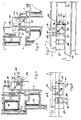
- a common fixed frame of a sliding folding element 2 consisting of a first wing 3, a second wing 4 and a third wing 5 is denoted by 1.
- This sliding-folding element is articulated with the aid of, for example, three rotating bands 6 arranged one above the other on the fixed frame 1 or on its vertical spar 7 on the band side.
- the first wing 3 is pivotally connected to the second wing 4 via at least two, but preferably also three rotary bearings 8, while the second wing 4 and the third wing 5 are rotatably connected via further rotary bearings 9.
- the immediately successive hinge groups are mounted alternately on the outside and on the inside of the sliding folding element 2. In this way it is possible to push the folded package toward the vertical spar on the hinge side, as shown in FIG. 3 of the drawing. Any other known arrangement of the individual wings and also a different number of wings are possible.
- the sliding element for example a sliding folding door, is displaceably mounted on a lower running rail 11 in the sense of the double arrow 12 via a lower carriage 10.
- a guide roller 13 or the like is provided at the upper end of the sliding folding element 2, which is guided in a guide rail 14.
- the arrangement can also be reversed, i.e. the weight can also be taken up.
- a closure, not shown, of this wing can be actuated, with the aid of which it is locked against the fixed frame 1.
- Another, located on the third wing 5 operating handle 16 is used to actuate a closure, not shown, through which the wings 4 and 5 can be pressed individually against the fixed frame, for example, locking bars which are up and down lock into the fixed frame 1.
- the locking device comprises at least two, but in the exemplary embodiment preferably three latching devices 17, 18 and 19.
- the first latching device 17 consists of a first latching member 20 and a first latching seat 21.
- the second latching device 18 comprises a second latching member 22 and a second latching seat 23.
- the third latching device 19 consists of the third latching member 24 and the third latching seat 25.
- the first latching seat 21 and the third latching seat 25 are designed as a common latching seat and consequently attached to a common component 26. This is attached to the first wing 3 in this way. that it points towards the latter when the first and second wings are folded together.
- control housing 27 which, when the first and second wings are folded together, projects against the first wing and thereby comes to lie directly next to the common component 26.
- control housing 27 is preferably attached to the upper corner of the second wing 4 associated with the third wing 5.
- the common component 26 lies close to the upper wing corner of the first wing 3 on the closing side.
- the first latching device 17 is designed in the manner of a cutter. Its spring-loaded latching element 20 can be displaced in the horizontal direction parallel to the wing plane and is provided with a corresponding entry and exit slope.
- the outer bevel of a nose 28 which delimits the latching receptacles 21 and 25 at this point, strikes the first latching member 20. It occurs against the resistance of a load spring into the interior of the control housing 27 and, when the wings 3 and 4 are in parallel, into the first latching receptacle 21.
- the third latching device 19 is in a disengaged or ineffective position when the second wing 4 is closed. From Fig. 6 it can be seen that the third locking member 24 is completely retracted into the interior of the control housing 27.
- the third latching element 24 can be moved outwards via a pusher 29 in the direction of the arrow 30 when the pusher 29 is in Arrow direction 31 is moved. The latter is the case according to FIG. 5 when the second wing 4 is opened.
- This displacement movement is transmitted via a coupling device 35 (FIG. 7) in the sense that the third locking member 24 carries out a displacement movement in the direction of arrow 30 and thereby engages behind the locking receptacle 25 of the component 26, whereby the wings 3 and 4 are coupled together.
- the coupling device 35 consists of an oblique slot 36, which extends in particular at 45 ° to the wing plane, and a bolt 37 which is displaceably guided therein.
- the oblique slot is located on the third latching element 24, and consequently the bolt 37 is held on the pusher 29.
- the second locking device 18 is also equipped with a pusher, which is designated 38. It can be inserted in the direction of arrow 40 against the resistance of a load spring 39. Its displacement movement is transmitted to the second locking member 22 via a coupling device 41.
- the coupling device 41 consists of an oblique slot 42, which is preferably located on the second latching member 22 and a bolt 43 of the pusher 38 which can be displaced therein.
- Both the loading spring 33 of the third latching device 19 and the loading spring 39 of the second latching device 18 each endeavor to do so Shift locking member 24 or 22 in the locking position. From Fig. 4 it can be seen that the second locking member 22 is in its locked position when the handle 38 is not loaded.
- the latter is pressed through the first wing 3 when it is approximately in a 180 ° open position (FIG. 7). This is because the surface 44 of the first wing 3 strikes the pusher 38. This means that the second wing 4 can only be opened when the first wing 3 has assumed an approximately parallel position to the second wing 4, being fixed with respect to the second wing 4 by means of the first latching device 17.
- Both the fixed frame 1 and the wings 2, 4 and 5 in the exemplary embodiment consist of profiled bars, preferably plastic profiled bars, the cross-sectional shapes of which are designed according to the drawing. From this it can also be seen that a stiffening profile 45, for example in the form of a rectangular tube, is inserted into a chamber of the profile bars of the fixed frame 1. A reinforcing profile 46 is inserted into a corresponding chamber of the profile bars of the wings 3, 4 and 5.
- the stiffening profiles particularly in the case of plastic profiles, do not extend into the wing corners because they would hinder the connection there, for example by ultrasonic welding.
Landscapes
- Extensible Doors And Revolving Doors (AREA)
- Seal Device For Vehicle (AREA)
- Lock And Its Accessories (AREA)
- Support Devices For Sliding Doors (AREA)
- Closing And Opening Devices For Wings, And Checks For Wings (AREA)
Claims (15)
- Porte ou fenêtre comportant un cadre dormant (1) et au moins deux vantaux (3, 4, 5) dont au moins un vantail est monté pivotant sur environ 180° sur son vantail voisin et les deux vantaux sont accouplables, à la position pliée d'ouverture du premier vantail (3), par un premier dispositif de verrouillage (17) détachable, constitué d'un premier organe d'arrêt (20) et d'un premier logement d'arrêt (21), le premier logement d'arrêt (21) étant disposé sur le premier vantail (3) et le premier organe d'arrêt (20) sur le deuxième vantail (4), ou inversement, et le premier dispositif de verrouillage (17) pouvant être verrouillé ou commandé par la fin du mouvement de 180° du premier vantail (3), un deuxième dispositif de verrouillage (18) étant constitué d'un deuxième organe d'arrêt (22) et d'un deuxième logement d'arrêt (23), le deuxième organe d'arrêt (22) étant disposé sur le deuxième vantail (4) et le deuxième logement d'arrêt (23) sur le cadre dormant (1), et le deuxième dispositif de verrouillage (18) pouvant être commandé par le mouvement d'ouverture du premier vantail (3), la position déverrouillée du deuxième dispositif de verrouillage (18) étant coordonnée à peu près à la position d'ouverture de 180° du premier vantail (3), du fait que la fin du mouvement pivotant d'ouverture de 180° du premier vantail (3), actionnant le deuxième dispositif de verrouillage, est en même temps un mouvement d'actionnement produisant le déverrouillage du deuxième dispositif de verrouillage (18), et le deuxième dispositif de verrouillage (18) comportant un organe d'actionnement, faisant saillie dans la trajectoire de mouvement du premier vantail (3), sous la forme d'un poussoir (38) chargé par ressort, qui est couplé au deuxième organe d'arrêt (22) par l'intermédiaire d'un dispositif de couplage (41), dont le ressort (39) charge l'organe d'arrêt (22) coordonné, tout au moins quand le poussoir (38) est enfoncé, dans le sens du verrouillage, et dont le mouvement de déverrouillage est orienté à peu près perpendiculairement au mouvement de déverrouillage du deuxième organe d'arrêt (22), caractérisé en ce que la porte est réalisée comme une porte coulissante et pliante, ou la fenêtre est réalisée comme une fenêtre coulissante et pliante, possédant au moins trois vantaux (3, 4, 5), et que le dispositif de couplage (41) est constitué d'une fente oblique (42) et d'une cheville (43) s'engageant en elle, la fente oblique (42) se trouvant en particulier sur le deuxième organe d'arrêt (22) et la cheville (43) sur le poussoir (38) coordonné.
- Porte ou fenêtre comportant un cadre dormant (1) et au moins deux vantaux (3, 4, 5) dont au moins un vantail est monté pivotant sur environ 180° sur son vantail voisin et les deux vantaux sont accouplables, à la position pliée d'ouverture du premier vantail (3), par un premier dispositif de verrouillage (17) détachable, constitué d'un premier organe d'arrêt (20) et d'un premier logement d'arrêt (21), le premier logement d'arrêt (21) étant disposé sur le premier vantail (3) et le premier organe d'arrêt (20) sur le deuxième vantail (4), ou inversement, et le premier dispositif de verrouillage (17) pouvant être verrouillé ou commandé par la fin du mouvement de 180° du premier vantail (3), un deuxième dispositif de verrouillage (18) étant constitué d'un deuxième organe d'arrêt (22) et d'un deuxième logement d'arrêt (23), le deuxième organe d'arrêt (22) étant disposé sur le deuxième vantail (4) et le deuxième logement d'arrêt (23) sur le cadre dormant (1), et le deuxième dispositif de verrouillage (18) pouvant être commandé par le mouvement d'ouverture du premier vantail (3), la position déverrouillée du deuxième dispositif de verrouillage (18) étant coordonnée à peu près à la position d'ouverture de 180° du premier vantail (3), du fait que la fin du mouvement pivotant d'ouverture de 180° du premier vantail (3), actionnant le deuxième dispositif de verrouillage, est en même temps un mouvement d'actionnement produisant le déverrouillage du deuxième dispositif de verrouillage (18), caractérisée en ce que la porte est réalisée comme une porte coulissante et pliante, ou la fenêtre est réalisée comme une fenêtre coulissante et pliante, possédant au moins trois vantaux (3, 4, 5), et qu'un troisième dispositif de verrouillage (19), constitué d'un troisième organe d'arrêt (24) et d'un troisième logement d'arrêt (25), est prévu pour accoupler avec verrouillage le premier vantail (3), ouvert sur environ 180°, au deuxième vantail (4), le troisième dispositif de verrouillage (19) pouvant être commandé par un début de mouvement d'ouverture du deuxième vantail (4) dans le sens du déverrouillage et la position déverrouillée du troisième dispositif de verrouillage (19) étant coordonnée au deuxième vantail (4) fermé.
- Dispositif selon la revendication 2, caractérisé en ce que le deuxième dispositif de verrouillage (18) comporte un organe d'actionnement (38) faisant saillie dans la trajectoire de mouvement du premier vantail (3) et couplé au deuxième organe d'arrêt (22).
- Dispositif selon une des revendications 1 à 3, caractérisé en ce que le premier organe d'arrêt (20) est réalisé à la façon d'un déclic et monté coulissant dans un boîtier de commande (27) du deuxième vantail (4), le premier logement d'arrêt (21) se trouvant sur le premier vantail (3).
- Dispositif selon la revendication 4, caractérisé en ce que les mouvements de verrouillage et de déverrouillage du premier organe d'arrêt (20) sont des mouvements horizontaux ou verticaux à peu près parallèles au plan du vantail.
- Dispositif selon au moins la revendication 2, caractérisé en ce que le troisième dispositif de verrouillage (19) comporte un organe d'actionnement (29), accouplé au troisième organe d'arrêt (24), qui fait saillie du deuxième vantail (4) vers le cadre dormant (1) et prend sa position de renversement pour le déverrouillage lorsque le deuxième vantail (4) est fermé.
- Dispositif selon au moins les revendications 3 et 6, caractérisé en ce que l'organe d'actionnement (38) pour le deuxième organe d'arrêt (22) et/ou l'organe d'actionnement (29) pour le troisième organe d'arrêt (24) est formé ou sont formés chacun par un poussoir chargé par ressort, chaque ressort de charge ou de rappel (33, 39) sollicitant l'organe d'arrêt (24, 22) coordonné dans le sens du verrouillage, tout au moins lorsque le poussoir est enfoncé.
- Dispositif selon la revendication 7, caractérisé en ce que les mouvements de déverrouillage du deuxième organe d'arrêt (22) et de son poussoir (38) coordonné et/ou du troisième organe d'arrêt (24) et de son poussoir (29) coordonné sont à peu près perpendiculaires entre eux et chaque organe d'arrêt est relié à son poussoir par un dispositif d'accouplement (35, 41).
- Dispositif selon la revendication 8, caractérisé en ce que le dispositif d'accouplement ou chaque dispositif d'accouplement (35, 41) est formé d'une fente oblique (36, 42) et d'une cheville (37, 43) ou d'un élément analogue engagé dans la fente, la fente oblique étant prévue en particulier sur le deuxième ou le troisième organe d'arrêt (22, 24) et la cheville ou l'élément analogue se trouvant chaque fois sur le poussoir coordonné (29, 38).
- Dispositif selon la revendication 9, caractérisé en ce que les poussoirs (29, 38) ainsi que le deuxième et le troisième organe d'arrêt (22, 24) sont montés mobiles en translation sur un ou sur chaque fois un boîtier de commande (27) ou analogue, relié au deuxième vantail (4), et que les deuxième et troisième dispositifs de verrouillage (18, 19) possèdent un boîtier de commande (27) ou analogue qui est commun et relié au deuxième vantail (4).
- Dispositif selon la revendication 10, caractérisé en ce que le deuxième logement d'arrêt (23) est disposé sur la traverse supérieure (14) du cadre dormant (1) et le boîtier de commande (27) ou analogue est disposé sur la traverse supérieure du deuxième vantail (4), en particulier dans la zone de l'angle supérieur coordonné au troisième vantail (5).
- Dispositif selon la revendication 11, caractérisé en ce que le deuxième logement d'arrêt (23) est formé par un rail de guidage (14) ou un rail de roulement et de suspension en haut du cadre dormant (1).
- Dispositif selon au moins la revendication 2, caractérisé en ce que le troisième organe d'arrêt (24) est mobile en translation à peu près à angle droit par rapport au deuxième organe d'arrêt (22), parallèlement au plan du deuxième vantail (4), le troisième organe d'arrêt (24) étant notamment mobile en translation à peu près en direction horizontale ou verticale.
- Dispositif selon la revendication 13, caractérisé en ce que le troisième logement d'arrêt (25) se trouve sur le premier vantail (3) et comporte une saillie d'arrêt (28), une réglette ou analogue, derrière laquelle vient se placer le troisième organe d'arrêt (24) à la position verrouillée, le premier et le troisième logement d'arrêt (21, 25) étant formés par une pièce commune (26) ou étant disposés sur une pièce commune.
- Dispositif selon au moins la revendication 2, caractérisé en ce que tous les organes d'arrêt (20, 22, 24) peuvent être verrouillés et déverrouillés parallèlement les uns aux autres en direction à peu près verticale, la pièce (26) commune venant s'engager au moins partiellement sous le boîtier de commande (27), notamment lorsque le premier et/ou le troisième dispositif de verrouillage (17, 18, 19) est verrouillé.
Priority Applications (1)
| Application Number | Priority Date | Filing Date | Title |
|---|---|---|---|
| AT89107837T ATE89639T1 (de) | 1988-05-18 | 1989-04-29 | Verriegelungsvorrichtung an einer schiebe-falttuer oder einem schiebe-faltfenster. |
Applications Claiming Priority (2)
| Application Number | Priority Date | Filing Date | Title |
|---|---|---|---|
| DE8806507U DE8806507U1 (de) | 1988-05-18 | 1988-05-18 | Verriegelungsvorrichtung an einer Schiebe-Falttür oder einem Schiebe-Faltfenster |
| DE8806507U | 1988-05-18 |
Publications (4)
| Publication Number | Publication Date |
|---|---|
| EP0342420A2 EP0342420A2 (fr) | 1989-11-23 |
| EP0342420A3 EP0342420A3 (en) | 1990-09-05 |
| EP0342420B1 EP0342420B1 (fr) | 1993-05-19 |
| EP0342420B2 true EP0342420B2 (fr) | 1997-06-04 |
Family
ID=6824164
Family Applications (1)
| Application Number | Title | Priority Date | Filing Date |
|---|---|---|---|
| EP89107837A Expired - Lifetime EP0342420B2 (fr) | 1988-05-18 | 1989-04-29 | Dispositif de fermeture pour porte ou fenêtre coulissantes et pliantes |
Country Status (3)
| Country | Link |
|---|---|
| EP (1) | EP0342420B2 (fr) |
| AT (1) | ATE89639T1 (fr) |
| DE (2) | DE8806507U1 (fr) |
Cited By (1)
| Publication number | Priority date | Publication date | Assignee | Title |
|---|---|---|---|---|
| DE102017100742B3 (de) * | 2017-01-16 | 2018-03-29 | Solarlux Gmbh | Verriegelbare Kopplungsvorrichtung |
Families Citing this family (2)
| Publication number | Priority date | Publication date | Assignee | Title |
|---|---|---|---|---|
| DE9209691U1 (de) * | 1992-07-18 | 1993-08-19 | Huwil-Werke GmbH Möbelschloß- und Beschlagfabriken, 53809 Ruppichteroth | Zentralverschluß für eine Falttür |
| DE19936018A1 (de) * | 1999-08-04 | 2001-02-08 | Siegenia Frank Kg | Verriegelungsvorrichtung für mindestens dreiflügelige Fenster und Türen ohne Mittelpfosten mit innenliegender Schlagleiste |
Family Cites Families (2)
| Publication number | Priority date | Publication date | Assignee | Title |
|---|---|---|---|---|
| GB396921A (en) * | 1932-06-25 | 1933-08-17 | George Sinclair Emerson | Automatic drawbolt device for use on double folded doors, windows, shutters and the like |
| DE583967C (de) * | 1932-07-22 | 1933-09-13 | Mathias Peters & Co | Fenster mit einem an dem am Blendrahmen anliegenden Fluegel ausschwenkbaren Fluegel und einem erst durch Ausschwenken des letzteren zugaenglichen Verschluss |
-
1988
- 1988-05-18 DE DE8806507U patent/DE8806507U1/de not_active Expired
-
1989
- 1989-04-29 AT AT89107837T patent/ATE89639T1/de not_active IP Right Cessation
- 1989-04-29 DE DE8989107837T patent/DE58904391D1/de not_active Expired - Fee Related
- 1989-04-29 EP EP89107837A patent/EP0342420B2/fr not_active Expired - Lifetime
Cited By (1)
| Publication number | Priority date | Publication date | Assignee | Title |
|---|---|---|---|---|
| DE102017100742B3 (de) * | 2017-01-16 | 2018-03-29 | Solarlux Gmbh | Verriegelbare Kopplungsvorrichtung |
Also Published As
| Publication number | Publication date |
|---|---|
| ATE89639T1 (de) | 1993-06-15 |
| EP0342420A3 (en) | 1990-09-05 |
| DE58904391D1 (de) | 1993-06-24 |
| DE8806507U1 (de) | 1988-07-07 |
| EP0342420B1 (fr) | 1993-05-19 |
| EP0342420A2 (fr) | 1989-11-23 |
Similar Documents
| Publication | Publication Date | Title |
|---|---|---|
| DE3234677C2 (de) | Beschlag für einen zumindest parallelabstellbaren Flügel eines Fensters, einer Tür od. dgl. | |
| DE68903724T2 (de) | Beschlag fuer tuer, fenster oder dergleichen. | |
| EP0021080B1 (fr) | Fenêtre ou porte levante, coulissante ou basculante | |
| DE2941109C2 (de) | Kipp-Schiebebeschlag für Fenster und Türen o.dgl. | |
| DE2445855C2 (de) | Sperrvorrichtung an Fenstern, Türen od. dgl. mit zwei in einem Rahmen mit festem Mittelpfosten nebeneinander angeordneten, voneinander unabhängig betätigbare Treibstangenverschlüsse aufweisenden Flügeln | |
| EP0231498B1 (fr) | Ferrure pour panneau de fenêtre, porte ou similaire pouvant au moins être basculé | |
| EP0342420B2 (fr) | Dispositif de fermeture pour porte ou fenêtre coulissantes et pliantes | |
| DE2421919C3 (de) | Fenster | |
| DE8711496U1 (de) | Verschluß für zweiflügelige Fenster, Türen od. dgl. | |
| EP0090956B2 (fr) | Ferrure pour une fenêtre, une porte ou analogues | |
| EP0098364B1 (fr) | Ferrure pour un vantail de fenêtre, porte ou similaire pouvant être basculé et par la suite être au moins déplacé selon un plan parallèle | |
| EP1614844A2 (fr) | Dispositif d'articulation | |
| DE1281889B (de) | Zentralverschluss fuer Fenster, Tueren od. dgl. mit einem Zwischenrahmen | |
| DE10129941B4 (de) | Verriegelungsmechanismus für Torflügel oder Fensterflügel | |
| DE2631453C2 (de) | Beschlag für Dachfenster | |
| EP4421285B1 (fr) | Porte coulissante avec un battant coulissant verrouillable | |
| DE3050971C3 (de) | Beschlag für den Schiebeflügel von Fenstern, Türen oder dgl. | |
| DE19906071C2 (de) | Drehbegrenzer für Dreh-Schiebe-Fenster | |
| CH688593A5 (de) | Faltbare Vorrichtung zum Verschliessen von Gebaeude oeffnungen, insbesondere fuer ein Faltdach oder Falttor. | |
| DE4308394A1 (de) | Beschlag für ein Fenster oder eine Tür | |
| DE4333724A1 (de) | Fensterflügel oder dergleichen | |
| DE1962906C3 (de) | Beschlag fur Dreh-Kipp- oder Dreh-Klappfenster | |
| EP3626918B1 (fr) | Ferrure pour une fenêtre, fenêtre | |
| DE1784947C3 (de) | Beschlag fur Drehkippfenster | |
| DE1919990C3 (de) | Schiebetüraufhängung, insbesondere für Kraftwagenschiebetüren |
Legal Events
| Date | Code | Title | Description |
|---|---|---|---|
| PUAI | Public reference made under article 153(3) epc to a published international application that has entered the european phase |
Free format text: ORIGINAL CODE: 0009012 |
|
| AK | Designated contracting states |
Kind code of ref document: A2 Designated state(s): AT CH DE FR GB LI |
|
| PUAL | Search report despatched |
Free format text: ORIGINAL CODE: 0009013 |
|
| AK | Designated contracting states |
Kind code of ref document: A3 Designated state(s): AT CH DE FR GB LI |
|
| 17P | Request for examination filed |
Effective date: 19900825 |
|
| D17Q | First examination report despatched (deleted) | ||
| GRAA | (expected) grant |
Free format text: ORIGINAL CODE: 0009210 |
|
| AK | Designated contracting states |
Kind code of ref document: B1 Designated state(s): AT CH DE FR GB LI |
|
| REF | Corresponds to: |
Ref document number: 89639 Country of ref document: AT Date of ref document: 19930615 Kind code of ref document: T |
|
| GBT | Gb: translation of ep patent filed (gb section 77(6)(a)/1977) |
Effective date: 19930519 |
|
| REF | Corresponds to: |
Ref document number: 58904391 Country of ref document: DE Date of ref document: 19930624 |
|
| ET | Fr: translation filed | ||
| PLBI | Opposition filed |
Free format text: ORIGINAL CODE: 0009260 |
|
| 26 | Opposition filed |
Opponent name: SIEGENIA-FRANK KG Effective date: 19940204 |
|
| APAC | Appeal dossier modified |
Free format text: ORIGINAL CODE: EPIDOS NOAPO |
|
| PLAW | Interlocutory decision in opposition |
Free format text: ORIGINAL CODE: EPIDOS IDOP |
|
| PUAH | Patent maintained in amended form |
Free format text: ORIGINAL CODE: 0009272 |
|
| STAA | Information on the status of an ep patent application or granted ep patent |
Free format text: STATUS: PATENT MAINTAINED AS AMENDED |
|
| 27A | Patent maintained in amended form |
Effective date: 19970604 |
|
| AK | Designated contracting states |
Kind code of ref document: B2 Designated state(s): AT CH DE FR GB LI |
|
| REG | Reference to a national code |
Ref country code: CH Ref legal event code: AEN Free format text: AUFRECHTERHALTUNG DES PATENTES IN GEAENDERTER FORM |
|
| ET3 | Fr: translation filed ** decision concerning opposition | ||
| GBTA | Gb: translation of amended ep patent filed (gb section 77(6)(b)/1977) |
Effective date: 19970910 |
|
| PGFP | Annual fee paid to national office [announced via postgrant information from national office to epo] |
Ref country code: GB Payment date: 19990315 Year of fee payment: 11 |
|
| PGFP | Annual fee paid to national office [announced via postgrant information from national office to epo] |
Ref country code: FR Payment date: 19990324 Year of fee payment: 11 Ref country code: AT Payment date: 19990324 Year of fee payment: 11 |
|
| PGFP | Annual fee paid to national office [announced via postgrant information from national office to epo] |
Ref country code: CH Payment date: 19990326 Year of fee payment: 11 |
|
| PG25 | Lapsed in a contracting state [announced via postgrant information from national office to epo] |
Ref country code: GB Free format text: LAPSE BECAUSE OF NON-PAYMENT OF DUE FEES Effective date: 20000429 Ref country code: AT Free format text: LAPSE BECAUSE OF NON-PAYMENT OF DUE FEES Effective date: 20000429 |
|
| PG25 | Lapsed in a contracting state [announced via postgrant information from national office to epo] |
Ref country code: LI Free format text: LAPSE BECAUSE OF NON-PAYMENT OF DUE FEES Effective date: 20000430 Ref country code: CH Free format text: LAPSE BECAUSE OF NON-PAYMENT OF DUE FEES Effective date: 20000430 |
|
| REG | Reference to a national code |
Ref country code: CH Ref legal event code: PL |
|
| GBPC | Gb: european patent ceased through non-payment of renewal fee |
Effective date: 20000429 |
|
| PG25 | Lapsed in a contracting state [announced via postgrant information from national office to epo] |
Ref country code: FR Free format text: LAPSE BECAUSE OF NON-PAYMENT OF DUE FEES Effective date: 20001229 |
|
| REG | Reference to a national code |
Ref country code: FR Ref legal event code: ST |
|
| PGFP | Annual fee paid to national office [announced via postgrant information from national office to epo] |
Ref country code: DE Payment date: 20040408 Year of fee payment: 16 |
|
| APAH | Appeal reference modified |
Free format text: ORIGINAL CODE: EPIDOSCREFNO |
|
| PG25 | Lapsed in a contracting state [announced via postgrant information from national office to epo] |
Ref country code: DE Free format text: LAPSE BECAUSE OF NON-PAYMENT OF DUE FEES Effective date: 20051101 |