EP0342420B2 - Locking device at a sliding folding door or window - Google Patents
Locking device at a sliding folding door or window Download PDFInfo
- Publication number
- EP0342420B2 EP0342420B2 EP89107837A EP89107837A EP0342420B2 EP 0342420 B2 EP0342420 B2 EP 0342420B2 EP 89107837 A EP89107837 A EP 89107837A EP 89107837 A EP89107837 A EP 89107837A EP 0342420 B2 EP0342420 B2 EP 0342420B2
- Authority
- EP
- European Patent Office
- Prior art keywords
- catch
- leaf
- movement
- arrangement
- wing
- Prior art date
- Legal status (The legal status is an assumption and is not a legal conclusion. Google has not performed a legal analysis and makes no representation as to the accuracy of the status listed.)
- Expired - Lifetime
Links
Images

Classifications
-
- E—FIXED CONSTRUCTIONS
- E05—LOCKS; KEYS; WINDOW OR DOOR FITTINGS; SAFES
- E05B—LOCKS; ACCESSORIES THEREFOR; HANDCUFFS
- E05B65/00—Locks or fastenings for special use
- E05B65/0085—Locks or fastenings for special use for folding wings, e.g. bi-fold wings
Definitions
- the invention relates to doors or windows according to the preambles of claims 1 and 2. Such doors or windows are known from GB-A-396,921.
- the fixed frame as well as the frames of the individual door or window sashes are constructed from frame bars.
- frame bars For this you can use solid bars or profiled bars made of plastic or aluminum.
- Plastic profiles are usually provided with a stiffening profile, which gives the spar in question the necessary strength that it would not have had with the usual wall thicknesses without such a stiffening profile.
- the stiffening profiles are made of steel or aluminum, for example. The bars are welded together at the frame corners. Because of this operation, the stiffening profiles cannot be led to the corner of the frame. The consequence of this is that the frames can essentially only absorb loads in the plane of the pane.
- DE-C-583 967 relates to a window on which two sashes are rotatably connected to one another so that an inner sash can be rotated through 180 ° and placed in front of the outer sash.
- the outer wing is connected to the frame in the manner of a rotating wing.
- a releasable first latching device consisting of a button and a spring is used. which is provided on each leg of two collapsible wings.
- the first locking device thus holds the two wings together.
- the package should only be able to be turned on the frame when the first sash has been placed on the second sash by 180 °.
- an actuating handle of a crest closure located on the outermost wings is arranged in such a way that it is covered by the respectively assigned, closed middle wing and is only accessible after the relevant middle wing has been completely opened so that the outer wing can be opened with the actuating handle.
- This actuating handle then simultaneously forms a safeguard against unintentional turning back of the inner wing.
- an automatically acting locking hook is then provided, which only releases the locking bar of the base lock when the wing package is turned back to close and is in contact with the frame.
- the object of the invention is on the one hand to provide a space-saving latching device which can be controlled by means of the first door or window wing for sliding folding doors or sliding folding windows with at least three leaves .
- the invention is further based on the object on sliding folding doors or sliding folding windows with at least three wings for an automatically secured connection of the two mutually fixed wings during the sliding folding movement of the two Wing existing package.
- the door or window is designed in accordance with the preamble of claim 1 in accordance with the characterizing part of this claim.
- the object mentioned in second place is achieved according to the invention in that the characterizing features of this claim are provided on a door or a window of the type of claim 2.
- the prerequisite for engaging the third latching device is a relatively slight opening movement of the second wing.
- the first must be securely fixed to it, and this secures the third latching device better than a clapper-like first latching device.
- the second locking device has an actuator which projects into the movement path of the first wing and which is coupled to the second locking member.
- a further embodiment of the invention according to claim 2 is that the first locking member is designed in the manner of a cutter and is slidably mounted in a control housing of the second wing, the first locking receptacle being located on the first wing. Cutters automatically move into the locked position when their spring-loaded locking element is in front of the locking fixture. The engagement and disengagement can take place solely by using the rotary movement of the first wing relative to the second.
- the first latching device can consist of several snappers or the like.
- the first latching element does not necessarily have to be a ball, even when it is designed in the manner of a snapper, but rather a spring-loaded latching element mounted in a sliding manner can also be used.
- appropriate slants should be used to engage and disengage with reasonable effort.
- this first latching device should also hold the two wings together well.
- the engagement and disengagement movement of the first locking member expediently runs approximately horizontally or vertically and parallel to the wing plane.
- the third latching device has an actuator coupled to the third latching member, which projects beyond the second wing against the fixed frame and assumes its disengaged switch position when the second wing is closed. So if you close the second wing, this results in the third latching element hitting the fixed frame, and when the actuator is pressed in, the third latching member changes from its latching position to a disengaging switching position in which it releases the first leaf .
- a further embodiment of the invention according to claim 2 is that the actuator for the second latching element and / or the actuator for the third latching element is a spring-loaded pusher, each loading spring, the associated latching element, at least when the pusher is pressed in, in the latching direction charged. This means that the second and / or third latching element is adjusted in the latching direction after the lever has been lifted from its abutting surface via the loading spring.
- Another preferred embodiment of the invention according to claim 2 is characterized in that the disengaging movement of the second latching member and its associated pusher and / or the third latching member and its associated pusher are directed approximately perpendicular to each other and each latching member is connected to its pusher via a coupling device.
- the associated adjustment movement of the latching element takes place via the latter when the pusher is adjusted.
- a parallel disengaging movement of the second and third latching members, in particular in the vertical direction, is also conceivable, the disengaging movements expediently running in opposite directions.
- the or each coupling device advantageously consists of an oblique slot and a bolt or the like engaging therein, in particular the oblique slot on the second or third latching element and the bolt or the like in each case being located on the associated pusher.
- a displacement movement is converted into a displacement movement that is transverse, preferably perpendicular, to it.
- other known devices for this reversal of movement for example control via tabs, is also possible.
- the second and the third latching device have a common control housing or the like connected to the second wing.
- the second locking receptacle is expediently arranged on the upper cross member of the fixed frame and the control housing or the like on the upper cross member of the second wing, in particular in the region of the upper corner assigned to the third wing.
- the second latching receptacle is formed by an upper guide rail or running rail of the fixed frame.
- a correspondingly projecting, downward-pointing profile web of the upper crossbar of the fixed frame can be used for locking purposes.
- the wings folded into a package can be slidably guided over a lower carriage on a running rail and a guide roller in the guide rail on the frame.
- the arrangement can also be reversed, i. that is, the supporting roller can be attached at the top and the guide roller at the bottom.
- the third latching element can advantageously be displaced approximately in the horizontal or vertical direction and thus makes the same displacement movement as the first latching element.
- This enables a further embodiment of the invention, which consists in the first and third snap-in receptacles being formed by a common component or being attached to it.
- a particularly preferred variant of the invention according to claim 2 results from claim 15. Through it the entire locking device can be used for right and left stop.
- a common fixed frame of a sliding folding element 2 consisting of a first wing 3, a second wing 4 and a third wing 5 is denoted by 1.
- This sliding-folding element is articulated with the aid of, for example, three rotating bands 6 arranged one above the other on the fixed frame 1 or on its vertical spar 7 on the band side.
- the first wing 3 is pivotally connected to the second wing 4 via at least two, but preferably also three rotary bearings 8, while the second wing 4 and the third wing 5 are rotatably connected via further rotary bearings 9.
- the immediately successive hinge groups are mounted alternately on the outside and on the inside of the sliding folding element 2. In this way it is possible to push the folded package toward the vertical spar on the hinge side, as shown in FIG. 3 of the drawing. Any other known arrangement of the individual wings and also a different number of wings are possible.
- the sliding element for example a sliding folding door, is displaceably mounted on a lower running rail 11 in the sense of the double arrow 12 via a lower carriage 10.
- a guide roller 13 or the like is provided at the upper end of the sliding folding element 2, which is guided in a guide rail 14.
- the arrangement can also be reversed, i.e. the weight can also be taken up.
- a closure, not shown, of this wing can be actuated, with the aid of which it is locked against the fixed frame 1.
- Another, located on the third wing 5 operating handle 16 is used to actuate a closure, not shown, through which the wings 4 and 5 can be pressed individually against the fixed frame, for example, locking bars which are up and down lock into the fixed frame 1.
- the locking device comprises at least two, but in the exemplary embodiment preferably three latching devices 17, 18 and 19.
- the first latching device 17 consists of a first latching member 20 and a first latching seat 21.
- the second latching device 18 comprises a second latching member 22 and a second latching seat 23.
- the third latching device 19 consists of the third latching member 24 and the third latching seat 25.
- the first latching seat 21 and the third latching seat 25 are designed as a common latching seat and consequently attached to a common component 26. This is attached to the first wing 3 in this way. that it points towards the latter when the first and second wings are folded together.
- control housing 27 which, when the first and second wings are folded together, projects against the first wing and thereby comes to lie directly next to the common component 26.
- control housing 27 is preferably attached to the upper corner of the second wing 4 associated with the third wing 5.
- the common component 26 lies close to the upper wing corner of the first wing 3 on the closing side.
- the first latching device 17 is designed in the manner of a cutter. Its spring-loaded latching element 20 can be displaced in the horizontal direction parallel to the wing plane and is provided with a corresponding entry and exit slope.
- the outer bevel of a nose 28 which delimits the latching receptacles 21 and 25 at this point, strikes the first latching member 20. It occurs against the resistance of a load spring into the interior of the control housing 27 and, when the wings 3 and 4 are in parallel, into the first latching receptacle 21.
- the third latching device 19 is in a disengaged or ineffective position when the second wing 4 is closed. From Fig. 6 it can be seen that the third locking member 24 is completely retracted into the interior of the control housing 27.
- the third latching element 24 can be moved outwards via a pusher 29 in the direction of the arrow 30 when the pusher 29 is in Arrow direction 31 is moved. The latter is the case according to FIG. 5 when the second wing 4 is opened.
- This displacement movement is transmitted via a coupling device 35 (FIG. 7) in the sense that the third locking member 24 carries out a displacement movement in the direction of arrow 30 and thereby engages behind the locking receptacle 25 of the component 26, whereby the wings 3 and 4 are coupled together.
- the coupling device 35 consists of an oblique slot 36, which extends in particular at 45 ° to the wing plane, and a bolt 37 which is displaceably guided therein.
- the oblique slot is located on the third latching element 24, and consequently the bolt 37 is held on the pusher 29.
- the second locking device 18 is also equipped with a pusher, which is designated 38. It can be inserted in the direction of arrow 40 against the resistance of a load spring 39. Its displacement movement is transmitted to the second locking member 22 via a coupling device 41.
- the coupling device 41 consists of an oblique slot 42, which is preferably located on the second latching member 22 and a bolt 43 of the pusher 38 which can be displaced therein.
- Both the loading spring 33 of the third latching device 19 and the loading spring 39 of the second latching device 18 each endeavor to do so Shift locking member 24 or 22 in the locking position. From Fig. 4 it can be seen that the second locking member 22 is in its locked position when the handle 38 is not loaded.
- the latter is pressed through the first wing 3 when it is approximately in a 180 ° open position (FIG. 7). This is because the surface 44 of the first wing 3 strikes the pusher 38. This means that the second wing 4 can only be opened when the first wing 3 has assumed an approximately parallel position to the second wing 4, being fixed with respect to the second wing 4 by means of the first latching device 17.
- Both the fixed frame 1 and the wings 2, 4 and 5 in the exemplary embodiment consist of profiled bars, preferably plastic profiled bars, the cross-sectional shapes of which are designed according to the drawing. From this it can also be seen that a stiffening profile 45, for example in the form of a rectangular tube, is inserted into a chamber of the profile bars of the fixed frame 1. A reinforcing profile 46 is inserted into a corresponding chamber of the profile bars of the wings 3, 4 and 5.
- the stiffening profiles particularly in the case of plastic profiles, do not extend into the wing corners because they would hinder the connection there, for example by ultrasonic welding.
Landscapes
- Extensible Doors And Revolving Doors (AREA)
- Seal Device For Vehicle (AREA)
- Lock And Its Accessories (AREA)
- Closing And Opening Devices For Wings, And Checks For Wings (AREA)
- Support Devices For Sliding Doors (AREA)
Abstract
Description
Die Erfindung betrifft Türen oder Fenster gemäß den Oberbegriffen der Patentansprüche 1 und 2. Derartige Türen oder Fenster sind aus der GB-A-396,921 bekannt.The invention relates to doors or windows according to the preambles of
Der feste Rahmen sowie die Rahmen der einzelnen Tür- oder Fensterflügel werden aus Rahmenholmen aufgebaut. Hierzu kann man massive Holme oder auch profilierte Holme aus Kunststoff oder Aluminium verwenden. Kunststoffprofile sind in der Regel mit einem Versteifungsprofil versehen, welches dem betreffenden Holm die notwendige Festigkeit verleiht, die er bei den üblichen Wandstärken ohne ein solches Versteifungsprofil nicht hätte. Die Versteifungsprofile bestehen beispielsweise aus Stahl oder Aluminium. Die Holme werden an den Rahmenecken miteinander verschweißt. Wegen dieses Arbeitsganges können die Versteifungsprofile nicht bis in die Rahmenecke geführt werden. Dies hat zur Folge, daß die Rahmen im wesentlichen nur Belastungen in der Scheibenebene aufnehmen können.The fixed frame as well as the frames of the individual door or window sashes are constructed from frame bars. For this you can use solid bars or profiled bars made of plastic or aluminum. Plastic profiles are usually provided with a stiffening profile, which gives the spar in question the necessary strength that it would not have had with the usual wall thicknesses without such a stiffening profile. The stiffening profiles are made of steel or aluminum, for example. The bars are welded together at the frame corners. Because of this operation, the stiffening profiles cannot be led to the corner of the frame. The consequence of this is that the frames can essentially only absorb loads in the plane of the pane.
Bei Flügeln von Schiebe-Falttüren oder Schiebe-Faltfenstern treten jedoch auch quer zur Rahmenebene verlaufende Belastungen auf. Wenn bei einer Schiebe - Falttür oder - fenster der letzte Flügel der Anordnung frei drehbar ist und er beim Falten des Elements schräg oder beispielsweise etwa senkrecht zum vorletzten Flügel steht, so versuchen die Gewichtskräfte dieses ersten Flügels die anschließenden Rahmen zu verwinden. Die Glasscheibe selbst kann den Flügel im wesentlichen nur in der Scheibenebene nicht jedoch senkrecht hierzu versteifen. Die Ecken selbst sind, wie gesagt, nicht steif genug und verwinden sich unter dieser Belastung etwas. Infolgedessen senkt sich der freie Flügel ab, und er streift dann unten im Falz- bzw. Schienenbereich.In the case of casements of sliding folding doors or sliding folding windows, however, loads also run transversely to the frame level. If the last leaf of the arrangement can be freely rotated in a sliding folding door or window and it is at an angle when folding the element or, for example, approximately perpendicular to the penultimate leaf, the weight of this first leaf tries to twist the subsequent frame. The glass pane itself can stiffen the wing essentially only in the plane of the pane but not perpendicular to it. As I said, the corners themselves are not stiff enough and twist somewhat under this load. As a result, the free wing lowers and it then grazes below in the rebate or rail area.
Die DE-C-583 967 betrifft ein Fenster, an welchem jeweils zwei Flügel drehbar miteinander verbunden sind, so daß jeweils ein innerer Flügel um 180° gedrehte und vor den äußeren Flügel gelegt werden kann.DE-C-583 967 relates to a window on which two sashes are rotatably connected to one another so that an inner sash can be rotated through 180 ° and placed in front of the outer sash.
Der äußere Flügel ist mit dem Blendrahmen in der Art eines Drehflügels verbunden.The outer wing is connected to the frame in the manner of a rotating wing.
Um zu vermeiden, daß der am festen Rahmen angelenkte Flügel in aufgeklappter Stellung durch den an ihm angelenkten Flügel senkrecht oder in einem Winkel zu seiner Ebene belastet und dadurch auf Verwinden beansprucht wird, dient eine aus einem Knopf und einer Feder bestehende, lösbare erste Verrasteinrichtung, welche jeweils an aufeinander liegenden Schenkel zweier zusammenklappbarer Flügel vorgesehen ist. Die erste Verrasteinrichtung hält somit die beiden Flügel zusammen. Weiterhin soll bei dem bekannten Fenster das Paket erst dann am Blendrahmen gedreht werden können, wenn der erste Flügel um 180° auf den zweiten Flügel gelegt wurde. Zu diesem Zweck ist ein Betätigungshandgriff eines an den äußersten Flügeln befindlichen Baskülverschlusses so angeordnet, daß er durch den jeweils zugeordneten, geschlossenen Mittelflügel verdeckt wird und nur nach dem vollständigen Öffnen des betreffenden Mittelflügels so zugänglich ist, daß mit dem Betätigungshandgriff der Außenflügel geöffnet werden kann. Dieser Betätigungshandgriff bildet dann gleichzeitig eine Sicherung gegen ein ungewolltes zurückdrehen des inneren Flügels. Zusätzlich ist dann noch ein automatisch wirkender Sperrhaken vorgesehen, welcher die Verschlußstange des Baskülverschlusses erst wieder freigibt, wenn das Flügelpaket zum Schließen zurückgedreht wird und am Blendrahmen anliegt.In order to prevent the wing hinged to the fixed frame from being loaded vertically or at an angle to its plane in the opened position by the wing hinged to it and thereby being subjected to twisting, a releasable first latching device consisting of a button and a spring is used. which is provided on each leg of two collapsible wings. The first locking device thus holds the two wings together. Furthermore, in the known window, the package should only be able to be turned on the frame when the first sash has been placed on the second sash by 180 °. For this purpose, an actuating handle of a crest closure located on the outermost wings is arranged in such a way that it is covered by the respectively assigned, closed middle wing and is only accessible after the relevant middle wing has been completely opened so that the outer wing can be opened with the actuating handle. This actuating handle then simultaneously forms a safeguard against unintentional turning back of the inner wing. In addition, an automatically acting locking hook is then provided, which only releases the locking bar of the base lock when the wing package is turned back to close and is in contact with the frame.
Bei Beschlägen für Schiebe - Falttüren bzw. Schiebe - Faltfenster ist nur mit Schwierigkeiten an dem Flügel, welcher über Rollen bzw. Führungen mit dem Blendrahmen verbunden ist, ein Verschluß anbringbar. Weiterhin ist bei der bekannten Fensteranordnung die Funktion des die Verschlußstange des Baskülverschlusses bewegenden Handgriff nicht automatisch.In the case of fittings for sliding / folding doors or sliding / folding windows, it is difficult to attach a lock to the sash, which is connected to the frame by rollers or guides. Furthermore, in the known window arrangement, the function of the handle moving the locking rod of the base lock is not automatic.
Bei modernen beispielsweise aus Kunststoffoder Aluminiumprofilen bestehenden Tür- oder Fensterrahmen ist auch im Sinne einer rationellen Lagerhaltung und einer kostengünstigen Montage die Zusammenfassung der verschiedenen Funktionen in einem Beschlagteil gefordert.In the case of modern door or window frames, for example made of plastic or aluminum profiles, it is also necessary to combine the various functions in one fitting part in the sense of efficient storage and cost-effective assembly.
Ausgehend von dem Stand der Technik nach der GB-A-396,921 besteht die Aufgabe der Erfindung zum einen darin, für Schiebe-Falttüren bzw. für Schiebe-Faltfenster mit wenigstens drei Flügeln eine platzsparende, mittels des ersten Tür- oder Fensterflügels steuerbare Verrasteinrichtung zu schaffen. Vor dem Hintergrund des genannten Standes der Technik liegt der Erfindung weiterhin die Aufgabe zugrunde, an Schiebe-Falttüren bzw. Schiebe-Faltfenstern mit wenigstens drei Flügeln für eine automatisiert gesicherte Verbindung der beiden aneinander festgelegten Flügel während der Schiebe-Falt-Bewegung des aus den beiden Flügeln bestehenden Pakets zu sorgen.Starting from the prior art according to GB-A-396,921, the object of the invention is on the one hand to provide a space-saving latching device which can be controlled by means of the first door or window wing for sliding folding doors or sliding folding windows with at least three leaves . Against the background of the cited prior art, the invention is further based on the object on sliding folding doors or sliding folding windows with at least three wings for an automatically secured connection of the two mutually fixed wings during the sliding folding movement of the two Wing existing package.
Zur Lösung der erstgenannten Aufgabe wird erfindungsgemäß vorgeschlagen, daß die Tür bzw. das Fenster gemäß dem Oberbegriff von Anspruch 1 entsprechend dem kennzeichnenden Teil dieses Anspruchs ausgebildet ist. Die an zweiter Stelle genannte Aufgabe wird erfindungsgemäß dadurch gelöst, daß an einer Tür oder einem Fenster der Gattung von Anspruch 2 die kennzeichnenden Merkmale dieses Anspruchs vorgesehen sind.To achieve the first-mentioned object, it is proposed according to the invention that the door or window is designed in accordance with the preamble of
Gemäß Anspruch 2 ist die Voraussetzung für das Einrasten der dritten Verrasteinrichtung eine verhältnismäßig geringfügige öffnungsbewegung des zweiten Flügels. Andererseits ist es so, daß gerade beim öffnen des zweiten Flügels der erste sicher daran fixiert sein muß und dies sichert die dritte Verrasteinrichtung besser als eine schnepperartige erste Verrasteinrichtung.According to claim 2, the prerequisite for engaging the third latching device is a relatively slight opening movement of the second wing. On the other hand, it is the case that when the second wing is opened, the first must be securely fixed to it, and this secures the third latching device better than a clapper-like first latching device.
In Weiterbildung der Erfindung nach Anspruch ist vorgesehen, daß die zweite Verrasteinrichtung einen in die Bewegungsbahn des ersten Flügels ragenden Betätiger aufweist, der mit dem zweiten Rastglied gekuppelt ist.In a further development of the invention according to claim it is provided that the second locking device has an actuator which projects into the movement path of the first wing and which is coupled to the second locking member.
In der Öffnungs - Endbewegung des ersten Flügels wirkt dieser auf den Betätiger ein und entriegelt die zweite Verrasteinrichtung. Umgekehrt gibt der erste Flügel zu Beginn seiner Schließ-Drehbewegung den Betätiger wieder frei. Die zweite Verrasteinrichtung kann infolgedessen wieder in Verraststellung gehen oder gebracht werden.In the opening and final movement of the first leaf, this acts on the actuator and unlocks the second locking device. Conversely, the first leaf releases the actuator again at the start of its closing rotary movement. As a result, the second latching device can go back into the latching position or be brought into it.
Eine weitere Ausgestaltung der Erfindung nach Anspruch 2 besteht darin, daß das erste Rastglied in der Art eines Schnepper ausgebildet ist und schiebbar in einem Steuergehäuse des zweiten Flügels gelagert ist, wobei sich die erste Rastaufnahme am ersten Flügel befindet. Schnepper treten automatisch in Sperrstellung, wenn ihr Federbelastetes Rastglied vor der Rastaufnahme steht. Das Ein- und Ausrasten kann allein unter Ausnutzung der Drehbewegung des ersten Flügels gegenüber dem zweiten erfolgen. Selbstverständlich kann die erste Rasteinrichtung aus mehreren Schneppern od. dgl. bestehen.A further embodiment of the invention according to claim 2 is that the first locking member is designed in the manner of a cutter and is slidably mounted in a control housing of the second wing, the first locking receptacle being located on the first wing. Cutters automatically move into the locked position when their spring-loaded locking element is in front of the locking fixture. The engagement and disengagement can take place solely by using the rotary movement of the first wing relative to the second. Of course, the first latching device can consist of several snappers or the like.
Das erste Rastglied muß auch bei der Ausbildung in der Art eines Schneppers nicht notwendigerweise eine Kugel sein, vielmehr ist auch ein schiebbar gelagertes, federbelastetes Rastglied brauchbar. Des weiteren sollte durch entsprechende Schrägen für ein Ein- und Ausrasten mit vernünftigem Kraftaufwand gesorgt werden. Andererseits soll aber diese erste Rasteinrichtung die beiden Flügel auch gut zusammenhalten. Die Ein- und Ausrastbewegung des ersten Rastglieds verläuft zweckmäßigerweise etwa horizontal oder vertikal und parallel zur Flügelebene.The first latching element does not necessarily have to be a ball, even when it is designed in the manner of a snapper, but rather a spring-loaded latching element mounted in a sliding manner can also be used. In addition, appropriate slants should be used to engage and disengage with reasonable effort. On the other hand, this first latching device should also hold the two wings together well. The engagement and disengagement movement of the first locking member expediently runs approximately horizontally or vertically and parallel to the wing plane.
In Weiterbildung der Erfindung nach Ansprüch 2 wird vorgeschlagen, daß die dritte Verrasteinrichtung einen mit dem dritten Rastglied gekuppelten Betätiger aufweist, welcher den zweiten Flügel gegen den festen Rahmen überragt und bei geschlossenem zweiten Flügel seine Ausrast - Umschaltstellung einnimmt. Wenn man also den zweiten Flügel schließt, so hat dies ein Auftreffen des dritten Rastglieds am festen Rahmen zur Folge, und beim Eindrücken des Betätigers geht das dritte Verrastglied von seiner Verrast- in eine Ausrast - Umschaltstellung, in welcher es den ersten Flügel freigibt, über.In a further development of the invention according to claim 2, it is proposed that the third latching device has an actuator coupled to the third latching member, which projects beyond the second wing against the fixed frame and assumes its disengaged switch position when the second wing is closed. So if you close the second wing, this results in the third latching element hitting the fixed frame, and when the actuator is pressed in, the third latching member changes from its latching position to a disengaging switching position in which it releases the first leaf .
Eine weitere Ausgestaltung der Erfindung nach Ansprüch 2 besteht darin, daß der Betätiger für das zweite Rastglied und/oder der Betätiger für das dritte Rastglied ein bzw. je ein federbelasteter Drücker ist, wobei jede Belastungsfeder das zugeordnete Rastglied, zumindest bei eingedrücktem Drücker, in Verrastrichtung belastet. Das bedeutet, daß das zweite und/oder dritte Rastglied nach dem Abheben seines Drückers von seiner anliegenden Fläche über die Belastungsfeder in Verrastrichtung verstellt wird.A further embodiment of the invention according to claim 2 is that the actuator for the second latching element and / or the actuator for the third latching element is a spring-loaded pusher, each loading spring, the associated latching element, at least when the pusher is pressed in, in the latching direction charged. This means that the second and / or third latching element is adjusted in the latching direction after the lever has been lifted from its abutting surface via the loading spring.
Eine weitere bevorzugte Ausführungsform der Erfindung nach Ansprüch 2 ist dadurch gekennzeichnet, daß die Ausrastbewegung des zweiten Rastglieds und seines zugeordneten Drückers und/oder des dritten Rastglieds und seines zugeordneten Drückers etwa senkrecht zueinander gerichtet sind und jedes Rastglied mit seinem Drücker über eine Kupplungsvorrichtung verbunden ist. Über letztere erfolgt beim Verstellen des Drückers die zugeordnete Verstellbewegung des Rastglieds. Denkbar ist auch eine parallele Ausrastbewegung des zweiten und dritten Rastglieds, insbesondere in vertikaler Richtung, wobei die Ausrastbewegungen zweckmäßigerweise in entgegengesetzten Richtungen verlaufen würden.Another preferred embodiment of the invention according to claim 2 is characterized in that the disengaging movement of the second latching member and its associated pusher and / or the third latching member and its associated pusher are directed approximately perpendicular to each other and each latching member is connected to its pusher via a coupling device. The associated adjustment movement of the latching element takes place via the latter when the pusher is adjusted. A parallel disengaging movement of the second and third latching members, in particular in the vertical direction, is also conceivable, the disengaging movements expediently running in opposite directions.
Die bzw. jede Kupplungsvorrichtung besteht vorteilhafterweise aus einem Schrägschlitz und einem darin eingreifenden Bolzen od. dgl., wobei sich insbesondere der Schrägschlitz am zweiten bzw. dritten Rastglied und der Bolzen od. dgl. jeweils am zugeordneten Drücker befindet. Hier wird über das Prinzip der schrägen Ebene eine Verschiebebewegung in eine hierzu quer, vorzugsweise senkrecht verlaufende Verschiebebewegung umgesetzt. Statt dessen ist auch die Anwendung anderer bekannter Einrichtungen für diese Bewegungsumkehr, beispielsweise eine Steuerung über Laschen, möglich.The or each coupling device advantageously consists of an oblique slot and a bolt or the like engaging therein, in particular the oblique slot on the second or third latching element and the bolt or the like in each case being located on the associated pusher. Here, using the principle of the inclined plane, a displacement movement is converted into a displacement movement that is transverse, preferably perpendicular, to it. Instead, the use of other known devices for this reversal of movement, for example control via tabs, is also possible.
Die zweite und die dritte Verrasteinrichtung weisen in Weiterbildung der Erfindung nach Ansprüch 2 ein gemeinsames, mit dem zweiten Flügel verbundenes Steuergehäuse od. dgl. auf. Die zweite Rastaufnahme ist zweckmäßigerweise am oberen Querholm des festen Rahmens und das Steuergehäuse od. dgl. am oberen Querholm des zweiten Flügels, insbesondere im Bereich der dem dritten Flügel zugeordneten oberen Ecke, angeordnet. Dadurch wird dann bei zusammengefaltetem ersten und zweiten Flügel der erste im Bereich seiner schließseitigen oberen Ecke festgehalten.In a further development of the invention, the second and the third latching device have a common control housing or the like connected to the second wing. The second locking receptacle is expediently arranged on the upper cross member of the fixed frame and the control housing or the like on the upper cross member of the second wing, in particular in the region of the upper corner assigned to the third wing. As a result, when the first and second sashes are folded together, the first is held in the area of its upper corner on the closing side.
Eine weitere Variante der Erfindung nach Ansprüch 2 ist dadurch gekennzeichnet, daß die zweite Rastaufnahme durch eine obere Führungsschiene oder Laufschiene des festen Rahmens gebildet ist. Statt dessen kann auch ein entsprechend vorstehender, nach unten weisender Profilsteg des oberen Querholms des festen Rahmens zu Verriegelungszwecken ausgenutzt werden. Im übrigen können die zu einem Paket zusammengeklappten Flügel über einen unteren Laufwagen auf einer Laufschiene und einer Führungsrolle in der Führungsschiene am Blendrahmen schiebbar geführt werden. Die Anordnung kann jedoch auch umgekehrt sein, d. h., man kann die tragende Rolle oben und die Führungsrolle unten anbringen.Another variant of the invention according to claim 2 is characterized in that the second latching receptacle is formed by an upper guide rail or running rail of the fixed frame. Instead, a correspondingly projecting, downward-pointing profile web of the upper crossbar of the fixed frame can be used for locking purposes. In addition, the wings folded into a package can be slidably guided over a lower carriage on a running rail and a guide roller in the guide rail on the frame. However, the arrangement can also be reversed, i. that is, the supporting roller can be attached at the top and the guide roller at the bottom.
Das dritte Rastglied ist in vorteilhafter Weise etwa in horizontaler oder in vertikaler Richtung verschiebbar und macht somit die gleiche Verschiebebewegung wie das erste Rastglied. Hierdurch ist eine weitere Ausgestaltung der Erfindung möglich, die darin besteht, daß die erste und dritte Rastaufnahme durch ein gemeinsames Bauteil gebildet oder daran angebracht sind.The third latching element can advantageously be displaced approximately in the horizontal or vertical direction and thus makes the same displacement movement as the first latching element. This enables a further embodiment of the invention, which consists in the first and third snap-in receptacles being formed by a common component or being attached to it.
Eine besonders bevorzugte Variante der Erfindung nach Ansprüch 2 ergibt sich aus Anspruch 15. Durch sie wird die gesamte Verriegelungsvorrichtung für Rechts - und Linksanschlag verwendbar.A particularly preferred variant of the invention according to claim 2 results from
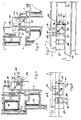
Die Erfindung wird nachstehend anhand der Zeichnung näher erläutert. Die Zeichnung zeigt ein Ausführungsbeispiel der Erfindung. Hierbei stellen dar:
- Fig. 1:
- eine Vorderansicht einer Schiebe-Falttür mit drei Flügeln,
- Fig. 2:
- eine Draufsicht auf die Fig. 1 bei geschlossenen Flügeln,
- Fig. 3:
- eine der Fig. 2 entsprechende Darstellung mit geöffneten und zusammengefalteten Flügeln,
- Fig. 4:
- in vergrößertem Maßstab einen Schnitt an der Stelle IV - IV der Fig. 1 bei geschlossenem zweiten Flügel,
- Fig. 5:
- eine vergleichbare Darstellung bei um 180° geöffnetem ersten und geringfügig geöffnetem zweiten Flügel,
- Fig. 6:
- eine Draufsicht auf Fig. 4 ohne den festen Rahmen,
- Fig. 7:
- eine dementsprechende Draufsicht auf Fig. 5.
- Fig. 1:
- a front view of a sliding folding door with three wings,
- Fig. 2:
- 2 shows a top view of FIG. 1 with the wings closed,
- Fig. 3:
- 2 corresponding representation with opened and folded wings,
- Fig. 4:
- on a larger scale a section at point IV - IV of FIG. 1 with the second wing closed,
- Fig. 5:
- a comparable representation with the first wing opened by 180 ° and the second wing slightly opened,
- Fig. 6:
- 4 without the fixed frame,
- Fig. 7:
- a corresponding plan view of FIG. 5.
Ein gemeinsamer fester Rahmen eines aus einem ersten Flügel 3, einem zweiten Flügel 4 sowie einem dritten Flügel 5 bestehenden Schiebe - Faltelements 2 ist mit 1 bezeichnet. Dieses Schiebe - Faltelement ist mit Hilfe von beispielsweisen drei übereinander angeordneten Drehbändern 6 am festen Rahmen 1 bzw. an dessen bandseitigem Vertikalholm 7 angelenkt. Des weiteren ist der erste Flügel 3 mit dem zweiten Flügel 4 über mindestens zwei, vorzugsweise aber ebenfalls drei Drehlager 8, schwenkbar verbunden, während der zweite Flügel 4 und der dritte Flügel 5 über weitere Drehlager 9 drehbar verbunden sind. Vorteilhafterweise sind die unmittelbar aufeinander folgenden Drehbändergruppen jeweils abwechselnd an der Außen- und an der Innenseite des Schiebe - Faltelements 2 anmontiert. Auf diese Weise ist ein Zurseiteschieben des zusammen gefalteten Pakets zum bandseitigen Vertikalholm hin möglich, wie Fig. 3 der Zeichnung zeigt. Jede andere bekannte Anordnung der einzelnen Flügel und auch eine andere Flügelzahl sind möglich.A common fixed frame of a sliding folding element 2 consisting of a
Das Schiebeelement, beispielsweise eine Schiebe - Falttür, ist über einen unteren Laufwagen 10 auf einer unteren Laufschiene 11 im Sinne des Doppelpfeils 12 verschiebbar gelagert. Außerdem ist noch eine Führungsrolle 13 od. dgl. am oberen Ende des Schiebe - Faltelements 2 vorgesehen, welche in einer Führungsschiene 14 geführt ist. Die Anordnung kann auch umgekehrt sein, d.h. das Gewicht kann auch oben aufgenommen werden.The sliding element, for example a sliding folding door, is displaceably mounted on a lower running rail 11 in the sense of the
Über den am ersten Flügel 3 angebrachten Bedienungsgriff 15 kann ein nicht näher dargestellter Verschluß dieses Flügels betätigt werden, mit dessen Hilfe er gegen den festen Rahmen 1 hin verriegelt ist. Ein weiterer, am dritten Flüg 5 befindlicher Bedienungsgriff 16 dient zur Betätigung eines nicht näher gezeigten Verschlusses, über welchen die Flügel 4 und 5 gegen den festen Rahmen hin einzeln gepresst werden können, wobei es sich zum Beispiel um Riegelstangen handelt, welche nach oben und unten in den festen Rahmen 1 einriegeln.Via the operating handle 15 attached to the
Die Verriegelungsvorrichtung umfaßt wenigstens zwei, beim Ausführungsbeispiel in bevorzugter Weise aber drei Verrasteinrichtungen 17, 18 und 19. Hierbei besteht die erste Verrasteinrichtung 17 aus einem ersten Rastglied 20 und einer ersten Rastaufnahme 21. Die zweite Verrasteinrichtung 18 umfaßt ein zweites Rastglied 22 und eine zweite Rastaufnahme 23. Die dritte Verrasteinrichtung 19 besteht aus dem dritten Rastglied 24 und der dritten Rastaufnahme 25. Gemäß Fig. 7 sind die erste Rastaufnahme 21 und die dritte Rastaufnahme 25 als gemeinsame Rastaufnahme ausgebildet und infolgedessen an einem gemeinsamen Bauteil 26 angebracht. Dieses ist am ersten Flügel 3 derart befestigt. daß es bei zusammengefaltetem ersten und zweiten Flügel gegen letzteren hin weist. Umgekehrt befindet sich am zweiten Flügel 4 ein Steuergehäuse 27, welches bei zusammengefaltetem ersten und zweiten Flügel gegen den ersten Flügel vorsteht und dabei unmittelbar neben dem gemeinsamen Bauteil 26 zu liegen kommt. Aus Fig. 1 ersieht man, daß das Steuergehäuse 27 vorzugsweise an der dem dritten Flügel 5 zugeordneten oberen Ecke des zweiten Flügels 4 angebracht ist. Demzufolge liegt das gemeinsame Bauteil 26 nahe der schließseitigen oberen Flügelecke des erste Flügels 3.The locking device comprises at least two, but in the exemplary embodiment preferably three
Die erste Verrasteinrichtung 17 ist in der Art eines Schneppers ausgebildet. Ihr federbelastetes Rastglied 20 ist in horizontaler Richtung parallel zur Flügelebene verschiebbar und mit entsprechender Einlauf - und Auslaufschräge versehen. Wenn man den ersten Flügel 3 um annähernd 180 geöffnet hat, trifft die Außenschräge einer Nase 28, welche die Rastaufnahme 21 und 25 an dieser Stelle begrenzt auf dem ersten Rastglied 20 auf. Es tritt gegen den Widerstand einer Belastungsfeder ins Innere des Steuergehäuses 27 und bei Parallellage der Flügel 3 und 4 in die erste Rastaufnahme 21 ein.The
Die dritte Verrasteinrichtung 19 befindet sich bei geschlossenem zweiten Flügel 4 in einer ausgerasteten oder wirkungslosen Stellung. Aus Fig. 6 ersieht man, daß dabei das dritte Rastglied 24 vollständig ins Innere des Steuergehäuses 27 zurückgezogen ist. Das dritte Rastglied 24 kann über einen Drücker 29 im Sinne des Pfeils 30 nach außen verschoben werden, wenn der Drücker 29 in Pfeilrichtung 31 verschoben wird. Letzteres ist gemäß Fig. 5 dann der Fall, wenn der zweite Flügel 4 geöffnet wird. Dabei kommt dann der gegen den Widerstand einer Belastungsfeder 33 bei geschlossenem Flügel 4 ins Steuergehäuse 27 eingeschobene Drücker 29 frei, und er kann sich relativ zum Steuergehäuse 27 in Pfeilrichtung 31 bewegen. Diese Verschiebebewegug wird über eine Kupplungsvorrichtung 35 (Fig. 7) in dem Sinne übertragen, daß das dritte Rastglied 24 eine Verschiebebewegung in Pfeilrichtung 30 durchführt und dabei hinter die Rastaufnahme 25 des Bauteils 26 greift, wodurch die Flügel 3 und 4 miteinander gekuppelt werden.The
Die Kupplungsvorrichtung 35 besteht aus einem insbesondere unter 45° zur Flügelebene verlaufenden Schrägschlitz 36 und einem darin verschiebbar geführten Bolzen 37. Der Schrägschlitz befindet sich am dritten Rastglied 24 und demzufolge ist der Bolzen 37 am Drükker 29 gehalten. Bei geschlossenem zweiten Flügel 4 liegt der einwärts geschobene Drücker 29 am oberen Querholm 34 des festen Rahmens 1 an, d. h. er wird durch die Schließbewegung des zweiten Flügels 4 gedrückt, was zum Ausrasten der dritten Verrasteinrichtung 19 führt. Beim Ausführungsbeispiel liegt der Drücker 29 an einem Schenkel der Führungsschiene 14 direkt oder indirekt an.The
Die zweite Verrasteinrichtung 18 ist gleichfalls mit einem Drücker ausgestattet, der mit 38 bezeichnet ist. Er kann gegen den Widerstand einer Belastungsfeder 39 in Pfeilrichtung 40 eingeschoben werden. Seine Verschiebebewegung wird über eine Kupplungsvorrichtung 41 auf das zweite Rastglied 22 übertragen. Die Kupplungsvorrichtung 41 besteht aus einem Schrägschlitz 42, der sich vorzugsweise am zweiten Rastglied 22 befindet und einem darin verschiebbaren Bolzen 43 des Drückers 38. Sowohl die Belastungsfeder 33 der dritten Verrasteinrichtung 19 als auch die Belastungsfeder 39 der zweiten Verrasteinrichtung 18 hat jeweils das Bestreben, ihr Rastglied 24 bzw. 22 in die Verriegelungsstellung zu verschieben. Aus Fig. 4 ersieht man, daß sich das zweite Rastglied 22 in seiner Verriegelungsstellung befindet, wenn der Drücker 38 nicht belastet ist. Letzterer wird durch den ersten Flügel 3 gedrückt, wenn sich dieser etwa in einer 180° -Öffnungsstellung befindet (Fig. 7). Dabei trifft nämlich die Fläche 44 des ersten Flügels 3 auf dem Drücker 38 auf. Das bedeutet, daß der zweite Flügel 4 nur dann geöffnet werden kann, wenn der erste Flügel 3 annähernd eine parallele Lage zum zweiten Flügel 4 eingenommen hat, wobei er mit Hilfe der ersten Verrasteinrichtung 17 gegenüber dem zweiten Flügel 4 fixiert ist.The
Sowohl der feste Rahmen 1 als auch die Flügel 2, 4 und 5 bestehen beim Ausführungsbeispiel aus Profilstäben, vorzugsweise Kunststoff - Profilstäben, deren Querschnittsformen gemäß der Zeichnung ausgebildet sind. Daraus ersieht man auch, daß in eine Kammer der Profilstäbe des festen Rahmens 1 ein Versteifungsprofil 45, beispielsweise Form eines Rechteckrohres, eingeschoben ist. In einer entsprechenden Kammer der Profilstäbe der Flügel 3, 4 und 5 ist jeweils ein Verstärkungsprofil 46 eingeschoben. Die Versteifungsprofile reichen aber, insbesondere bei Kunststoffprofilen, nicht bis in die Flügelecken, weil sie dort das Verbinden, beispielsweise durch Ultraschallschweißung, behindern würden.Both the fixed
Claims (15)
- A door or window with a fixed frame (1) and at least two leaves (3, 4, 5), at least one leaf being mounted on its neighbour leaf such that it is rotatable through about 180°, and both leaves, when the first leaf (3) is in the opened-out position, are capable of being coupled by a releasable catch arrangement (17) consisting of a first catch member (20) and a first catch housing (21), the first catch housing (21) being disposed on the first leaf (3) and the first catch member (20) being disposed on the second leaf (4) or vice versa, the first catch arrangement (17) being capable of being engaged or controlled by the 180° end movement of the first leaf (3), and with a second catch arrangement (18) consisting of a second catch member (22) and a second catch housing (23), the second catch member (22) being disposed on the second leaf (4) and the second catch housing (23) being disposed on the fixed frame (1) and it being possible for the second catch arrangement (18) to be controlled by the opening movement of the first leaf (3), wherein the disengaged setting of the second catch arrangement (18) has associated to it the 180° open setting of the first leaf (3), in that the opening end movement of the 180° opening rotational movement of the leaf (3) activating the second catch arrangement (18) is, at the same time, a disengaging actuating movement of the second catch arrangement (18) and wherein the second catch arrangement (18) comprises an actuator in the form of a spring-loaded pressing member (38) which extends into the path of movement of the first leaf, and which is coupled to the second catch member via a coupling device (41), and this biasing spring (39) loads the associated catch member (22) in the direction of engagement, at least when the pressing member (38) is pressed in, and the disengaging movement thereof is directed approximately perpendicular to the disengaging movement of the second catch member (22), characterised in that the door is constructed as a slidingfolding door or the window is constructed as a sliding-folding window with at least 3 leaves (3,4,5,); and in that the coupling device (41) consists of an angular slot (42) and a pin (43) which engages therein, wherein, in particular, the angular slot (42) is located on the second catch member (22) and the pin (43) is located on the associated pressing member (38).
- Door or window with a fixed frame (1) and at least two leaves (3,4,5), at least one leaf being mounted on its neighbour leaf such that it is rotatable through about 180°, and both leaves, when the first leaf (3) is in the opened-out position, are capable of being coupled via a first catch arrangement (17) which is detachable and consists of a first catch member (20) and a first catch housing (21), wherein the first catch housing (21) is mounted on the first leaf (3) and the first catch member (20) is mounted on the second leaf (4) or vice versa, and the first catch arrangement (17) can be engaged or controlled by means of the 180° end movement of the first wing (3) in having a second catch arrangement (18) consisting of a second catch member (22) and a second catch housing (23), wherein the second catch member (22) is disposed on the second wing (4) and the second catch housing (23) is disposed on the fixed frame (1) and the second catch arrangement (18) can be controlled by means of the opening movement of the first leaf (3), wherein the engaged position of the second catch arrangement (18) is approximately allocated to the 180° open position of the first leaf (3), in that the open end position of the 180° open rotational movement is allocated to the first leaf (3), in that the open end movement of the 180° opening rotational movement of the first leaf (3) which actuates the second catch arrangement is, at the same time, a disengaging movement of the second catch arrangement (18), characterised in that the door is formed as a sliding-folding door, or the window is formed as a sliding-folding window, with at least three leaves (3, 4, 5), and in that a third catch arrangement (19), consisting of a third catch member (24) and a third catch housing (25) is provided for the engaging coupling of the first leaf (3) on the second leaf (4), which leaf is opened by approximately 180°, wherein the third catch arrangement (19) can be controlled by means of a start-opening movement of the second leaf (4) in the locking direction, and the locked second leaf (4) is allocated to the unbolted position of the third control device (19).
- Device according to Claim 2,
characterised in that the second catch arrangement (18) comprises an actuator (38) which extends into the path of movement of the first leaf (3) and which is coupled to the second catch member (22). - Device according to one of Claims 1 to 3, characterised in that the first catch member (20) is formed in the manner of a snap-fastening and is mounted displaceably in a control housing (27) of the second leaf (4), wherein the first catch aperture (21) is located on the first leaf (3).
- Device according to CLaim 4,
characterised by a horizontal or vertical engaging and disengaging movement of the first catch member (20), which movement is approximately parallel to the leaf plane. - Device according to at least Claim 2, characterised in that the third catch arrangement (19) comprises an activating member (29) which is coupled to the third engaging member (24) and which projects beyond the second leaf (4) and towards the fixed frame (1), assuming its disengaging switch-over position when the second leaf (4) is closed.
- Device according to Claims 3 and 6,
characterised in that the actuator (38) for the second catch member (22) and/or the actuator (29) for the third catch member (24) is one or a respective spring-loaded push member, each biasing spring (33, 39) loading the associated catch member (24, 22) in the engagement direction at least when the push member is pushed in. - Device according to Claim 7,
characterised in that the disengagement movement (38) of the second catch member (22) and of its associated push member (38) and/or of the third catch member (24) and of its associated push member (29) are directed substantially perpendicular to one another and in that each catch member is connected to its push member via a coupling device (35, 41). - Device according to Claim 8,
characterised in that the or each coupling device (35, 41) consists of an inclined slot (36, 42) and, engaging therein, a bolt (37, 43) or the like, particularly the inclined slot on the second and/or third catch member (22, 24) and the bolt or the like being in each case disposed on the associated push member (29, 38). - Device according to Claim 9,
characterised in that the push members (29, 38) and the second and third catch members (22, 24) are displaceably mounted on one or on each control housing (288) or the like connected to the second leaf (4), and in that the second and the third catch arrangements (18, 19) have a common control housing (27) or the like connected to the second leaf (4). - Device according to Claim 10,
characterised in that the second catch housing (23) is disposed on the upper transverse member (14) of the fixed frame (1) while the control housing (27) or the like is disposed on the upper transverse member of the second leaf (4), particularly in the region of the upper corner associated with the third leaf (5). - Device according to Claim 11,
characterised in that the second catch housing (23) is formed by an upper guide rail (14) or runner of the fixed frame (1). - Device according to Claim 2,
characterised in that the third catch member (24) is displaceable substantially perpendicular to the second catch member (22) and parallel to the plane of the second leaf (4), the third catch member (24) being adapted to slide particularly in a substantially horizontal or vertical direction. - Device according to Claim 13,
characterised in that the third catch housing (25) is disposed on the first leaf (3) and has a catch nose (28) or catch strip or the like behind which, in the engaged position, the third catch member (34) engages, the first and third catch housings (21, 25) being formed by or being provided on a common component (26). - Device according to Claim 2,
characterised in that all catch members (20, 22, 24) are capable of being engaged and disengaged in a substantially vertical direction and parallel with one another, wherein, particularly when the first and/or third catch arrangement (17, 18, 19) are engaged, the common component (26) engages at least partially under the control housing (27).
Priority Applications (1)
| Application Number | Priority Date | Filing Date | Title |
|---|---|---|---|
| AT89107837T ATE89639T1 (en) | 1988-05-18 | 1989-04-29 | LOCKING DEVICE ON A SLIDING-FOLDING DOOR OR SLIDING-FOLDING WINDOW. |
Applications Claiming Priority (2)
| Application Number | Priority Date | Filing Date | Title |
|---|---|---|---|
| DE8806507U DE8806507U1 (en) | 1988-05-18 | 1988-05-18 | Locking device on a sliding-folding door or sliding-folding window |
| DE8806507U | 1988-05-18 |
Publications (4)
| Publication Number | Publication Date |
|---|---|
| EP0342420A2 EP0342420A2 (en) | 1989-11-23 |
| EP0342420A3 EP0342420A3 (en) | 1990-09-05 |
| EP0342420B1 EP0342420B1 (en) | 1993-05-19 |
| EP0342420B2 true EP0342420B2 (en) | 1997-06-04 |
Family
ID=6824164
Family Applications (1)
| Application Number | Title | Priority Date | Filing Date |
|---|---|---|---|
| EP89107837A Expired - Lifetime EP0342420B2 (en) | 1988-05-18 | 1989-04-29 | Locking device at a sliding folding door or window |
Country Status (3)
| Country | Link |
|---|---|
| EP (1) | EP0342420B2 (en) |
| AT (1) | ATE89639T1 (en) |
| DE (2) | DE8806507U1 (en) |
Cited By (1)
| Publication number | Priority date | Publication date | Assignee | Title |
|---|---|---|---|---|
| DE102017100742B3 (en) * | 2017-01-16 | 2018-03-29 | Solarlux Gmbh | Lockable coupling device |
Families Citing this family (2)
| Publication number | Priority date | Publication date | Assignee | Title |
|---|---|---|---|---|
| DE9209691U1 (en) * | 1992-07-18 | 1993-08-19 | Huwil-Werke GmbH Möbelschloß- und Beschlagfabriken, 53809 Ruppichteroth | Central lock for a folding door |
| DE19936018A1 (en) * | 1999-08-04 | 2001-02-08 | Siegenia Frank Kg | Locking system for a window/door with three or more panels and without a center post has an inner bar with a bolt and a closure to secure the center panel frame to a flanking panel |
Family Cites Families (2)
| Publication number | Priority date | Publication date | Assignee | Title |
|---|---|---|---|---|
| GB396921A (en) * | 1932-06-25 | 1933-08-17 | George Sinclair Emerson | Automatic drawbolt device for use on double folded doors, windows, shutters and the like |
| DE583967C (en) * | 1932-07-22 | 1933-09-13 | Mathias Peters & Co | Window with a wing that can be swung out on the wing adjacent to the frame and a lock that is only accessible by swiveling the latter out |
-
1988
- 1988-05-18 DE DE8806507U patent/DE8806507U1/en not_active Expired
-
1989
- 1989-04-29 DE DE8989107837T patent/DE58904391D1/en not_active Expired - Fee Related
- 1989-04-29 AT AT89107837T patent/ATE89639T1/en not_active IP Right Cessation
- 1989-04-29 EP EP89107837A patent/EP0342420B2/en not_active Expired - Lifetime
Cited By (1)
| Publication number | Priority date | Publication date | Assignee | Title |
|---|---|---|---|---|
| DE102017100742B3 (en) * | 2017-01-16 | 2018-03-29 | Solarlux Gmbh | Lockable coupling device |
Also Published As
| Publication number | Publication date |
|---|---|
| EP0342420B1 (en) | 1993-05-19 |
| EP0342420A3 (en) | 1990-09-05 |
| ATE89639T1 (en) | 1993-06-15 |
| DE58904391D1 (en) | 1993-06-24 |
| EP0342420A2 (en) | 1989-11-23 |
| DE8806507U1 (en) | 1988-07-07 |
Similar Documents
| Publication | Publication Date | Title |
|---|---|---|
| DE3234677C2 (en) | Fitting for an at least parallel hinged wing of a window, door or the like. | |
| DE68903724T2 (en) | FITTING FOR DOORS, WINDOWS OR THE LIKE. | |
| EP0021080B1 (en) | Lifting, sliding or swinging door or window | |
| DE2941109C2 (en) | Tilt and slide fitting for windows and doors or the like. | |
| DE2445855C2 (en) | Locking device on windows, doors or the like with two wings that are arranged next to one another in a frame with a fixed central post and can be operated independently of one another and have espagnolette locks | |
| EP0231498B1 (en) | Fittings for a wing of a window, door or the like which is at least tiltable | |
| EP0342420B2 (en) | Locking device at a sliding folding door or window | |
| DE2421919C3 (en) | window | |
| DE8711496U1 (en) | Lock for double-leaf windows, doors, etc. | |
| EP0090956B2 (en) | Mounting for a window, a door or the like | |
| EP0098364B1 (en) | Fitting for a tiltable and subsequently at least adjustable-in-parallel wing of a window, a door or like | |
| EP1614844A2 (en) | Pivot device | |
| DE1281889B (en) | Central lock for windows, doors or the like with an intermediate frame | |
| DE10129941B4 (en) | Locking mechanism for leaf or sash | |
| DE2631453C2 (en) | Fitting for roof windows | |
| EP4421285B1 (en) | Sliding door with a lockable sliding wing | |
| DE3050971C3 (en) | Fitting for the sliding sash of windows, doors or the like. | |
| DE19906071C2 (en) | Turn limiter for turn-slide windows | |
| CH688593A5 (en) | Folding cover for opening in building | |
| DE4308394A1 (en) | Fitting for a window or a door | |
| DE4333724A1 (en) | Casement or the like | |
| DE1962906C3 (en) | Hardware for turn-tilt or turn-tilt windows | |
| EP3626918B1 (en) | Fitting for a window, window | |
| DE1784947C3 (en) | Hardware for tilt and turn windows | |
| DE1919990C3 (en) | Sliding door suspension, in particular for motor vehicle sliding doors |
Legal Events
| Date | Code | Title | Description |
|---|---|---|---|
| PUAI | Public reference made under article 153(3) epc to a published international application that has entered the european phase |
Free format text: ORIGINAL CODE: 0009012 |
|
| AK | Designated contracting states |
Kind code of ref document: A2 Designated state(s): AT CH DE FR GB LI |
|
| PUAL | Search report despatched |
Free format text: ORIGINAL CODE: 0009013 |
|
| AK | Designated contracting states |
Kind code of ref document: A3 Designated state(s): AT CH DE FR GB LI |
|
| 17P | Request for examination filed |
Effective date: 19900825 |
|
| D17Q | First examination report despatched (deleted) | ||
| GRAA | (expected) grant |
Free format text: ORIGINAL CODE: 0009210 |
|
| AK | Designated contracting states |
Kind code of ref document: B1 Designated state(s): AT CH DE FR GB LI |
|
| REF | Corresponds to: |
Ref document number: 89639 Country of ref document: AT Date of ref document: 19930615 Kind code of ref document: T |
|
| GBT | Gb: translation of ep patent filed (gb section 77(6)(a)/1977) |
Effective date: 19930519 |
|
| REF | Corresponds to: |
Ref document number: 58904391 Country of ref document: DE Date of ref document: 19930624 |
|
| ET | Fr: translation filed | ||
| PLBI | Opposition filed |
Free format text: ORIGINAL CODE: 0009260 |
|
| 26 | Opposition filed |
Opponent name: SIEGENIA-FRANK KG Effective date: 19940204 |
|
| APAC | Appeal dossier modified |
Free format text: ORIGINAL CODE: EPIDOS NOAPO |
|
| PLAW | Interlocutory decision in opposition |
Free format text: ORIGINAL CODE: EPIDOS IDOP |
|
| PUAH | Patent maintained in amended form |
Free format text: ORIGINAL CODE: 0009272 |
|
| STAA | Information on the status of an ep patent application or granted ep patent |
Free format text: STATUS: PATENT MAINTAINED AS AMENDED |
|
| 27A | Patent maintained in amended form |
Effective date: 19970604 |
|
| AK | Designated contracting states |
Kind code of ref document: B2 Designated state(s): AT CH DE FR GB LI |
|
| REG | Reference to a national code |
Ref country code: CH Ref legal event code: AEN Free format text: AUFRECHTERHALTUNG DES PATENTES IN GEAENDERTER FORM |
|
| ET3 | Fr: translation filed ** decision concerning opposition | ||
| GBTA | Gb: translation of amended ep patent filed (gb section 77(6)(b)/1977) |
Effective date: 19970910 |
|
| PGFP | Annual fee paid to national office [announced via postgrant information from national office to epo] |
Ref country code: GB Payment date: 19990315 Year of fee payment: 11 |
|
| PGFP | Annual fee paid to national office [announced via postgrant information from national office to epo] |
Ref country code: FR Payment date: 19990324 Year of fee payment: 11 Ref country code: AT Payment date: 19990324 Year of fee payment: 11 |
|
| PGFP | Annual fee paid to national office [announced via postgrant information from national office to epo] |
Ref country code: CH Payment date: 19990326 Year of fee payment: 11 |
|
| PG25 | Lapsed in a contracting state [announced via postgrant information from national office to epo] |
Ref country code: GB Free format text: LAPSE BECAUSE OF NON-PAYMENT OF DUE FEES Effective date: 20000429 Ref country code: AT Free format text: LAPSE BECAUSE OF NON-PAYMENT OF DUE FEES Effective date: 20000429 |
|
| PG25 | Lapsed in a contracting state [announced via postgrant information from national office to epo] |
Ref country code: LI Free format text: LAPSE BECAUSE OF NON-PAYMENT OF DUE FEES Effective date: 20000430 Ref country code: CH Free format text: LAPSE BECAUSE OF NON-PAYMENT OF DUE FEES Effective date: 20000430 |
|
| REG | Reference to a national code |
Ref country code: CH Ref legal event code: PL |
|
| GBPC | Gb: european patent ceased through non-payment of renewal fee |
Effective date: 20000429 |
|
| PG25 | Lapsed in a contracting state [announced via postgrant information from national office to epo] |
Ref country code: FR Free format text: LAPSE BECAUSE OF NON-PAYMENT OF DUE FEES Effective date: 20001229 |
|
| REG | Reference to a national code |
Ref country code: FR Ref legal event code: ST |
|
| PGFP | Annual fee paid to national office [announced via postgrant information from national office to epo] |
Ref country code: DE Payment date: 20040408 Year of fee payment: 16 |
|
| APAH | Appeal reference modified |
Free format text: ORIGINAL CODE: EPIDOSCREFNO |
|
| PG25 | Lapsed in a contracting state [announced via postgrant information from national office to epo] |
Ref country code: DE Free format text: LAPSE BECAUSE OF NON-PAYMENT OF DUE FEES Effective date: 20051101 |