EP0221238B1 - Encodeur tolérant aux erreurs pour la conversion d'un code thermomètre en un code binaire - Google Patents
Encodeur tolérant aux erreurs pour la conversion d'un code thermomètre en un code binaire Download PDFInfo
- Publication number
- EP0221238B1 EP0221238B1 EP86109119A EP86109119A EP0221238B1 EP 0221238 B1 EP0221238 B1 EP 0221238B1 EP 86109119 A EP86109119 A EP 86109119A EP 86109119 A EP86109119 A EP 86109119A EP 0221238 B1 EP0221238 B1 EP 0221238B1
- Authority
- EP
- European Patent Office
- Prior art keywords
- code
- thermometer
- bit
- binary
- thermometer code
- Prior art date
- Legal status (The legal status is an assumption and is not a legal conclusion. Google has not performed a legal analysis and makes no representation as to the accuracy of the status listed.)
- Expired - Lifetime
Links
Images
Classifications
-
- H—ELECTRICITY
- H03—ELECTRONIC CIRCUITRY
- H03M—CODING; DECODING; CODE CONVERSION IN GENERAL
- H03M7/00—Conversion of a code where information is represented by a given sequence or number of digits to a code where the same, similar or subset of information is represented by a different sequence or number of digits
- H03M7/14—Conversion to or from non-weighted codes
- H03M7/16—Conversion to or from unit-distance codes, e.g. Gray code, reflected binary code
- H03M7/165—Conversion to or from thermometric code
-
- G—PHYSICS
- G06—COMPUTING; CALCULATING OR COUNTING
- G06F—ELECTRIC DIGITAL DATA PROCESSING
- G06F11/00—Error detection; Error correction; Monitoring
- G06F11/07—Responding to the occurrence of a fault, e.g. fault tolerance
- G06F11/08—Error detection or correction by redundancy in data representation, e.g. by using checking codes
- G06F11/085—Error detection or correction by redundancy in data representation, e.g. by using checking codes using codes with inherent redundancy, e.g. n-out-of-m codes
-
- H—ELECTRICITY
- H03—ELECTRONIC CIRCUITRY
- H03M—CODING; DECODING; CODE CONVERSION IN GENERAL
- H03M7/00—Conversion of a code where information is represented by a given sequence or number of digits to a code where the same, similar or subset of information is represented by a different sequence or number of digits
- H03M7/02—Conversion to or from weighted codes, i.e. the weight given to a digit depending on the position of the digit within the block or code word
- H03M7/04—Conversion to or from weighted codes, i.e. the weight given to a digit depending on the position of the digit within the block or code word the radix thereof being two
Definitions
- the present invention relates to a method and an apparatus for converting a thermometer code into a corresponding binary code.
- a number may be represented by a thermometer code wherein successive bits of a data word are assigned progressively larger values, all of the bits having assigned values below or the same as the number being set to a logical true state, and all of the bits having values higher than the number being set to a logical false state.
- A/D analog-to-digital
- a reference voltage is divided into a set of progressively smaller reference voltage quantum levels and a comparator associated with each quantum level compares an analog input voltage with the voltage quantum, generating an output true state if the input voltage is higher than the voltage quantum reference.
- the outputs of all of the comparators thus form the bits of a thermometer code representing the magnitude of the input voltage when arranged in order of the associated reference voltage quantum level magnitudes.
- thermometer codes do not represent numbers efficiently in terms of the number of bits required. For instance, an eight bit thermometer code can represent any one of 9 different numbers (including 0) while a typical eight bit binary code can represent 256 different numbers. Therefore the thermometer code output of an A/D converter is usually converted by an encoding circuit to another more compact and useful binary code before being transmitted as data to external circuits.
- thermometer code bits of the thermometer code are out-of-sequence, i.e., when logical-true bits in the code are separated by one or more intervening logical-false bits.
- This can sometimes happen when the thermometer code is produced by an A/D converter when sampling a high frequency signal if the individual comparators of the converter do not all switch at the same speed. For instance, if the input voltage is falling at the time it is sampled, a lower order comparator which is relatively fast may switch to a low output state before a higher order comparator, which is relatively slower, switches.
- thermometer-to-binary encoder When the out-of-sequence thermometer code is applied as an input to a typical thermometer-to-binary encoder, the output of the thermometer-to-binary encoder bears little relation to the actual magnitude of the sampled voltage. It has been shown experimentally that for many A/D converters a good approximation of the most likely particular magnitude of a sampled voltage which produces an out-of-sequence thermometer code is obtained by simply counting the logical-true bits in the out-of-sequence thermometer code. It would be advantageous if the thermometer-to-binary encoder would produce a binary code output in response to an out-of-sequence thermometer code input which would be as close as possible to this "ideal" approximation result. It should be noted that the technique of counting the logical-true bits also correctly encodes an in-sequence thermometer code input.
- thermometer-to-binary code converter which is based upon an odd-bit thermometer code where the central bit becomes the most significant bit of the output binary code and is used as an enable signal for one of two ROMs.
- the remaining bits are divided into two equal subsets of adjacent bits that serve to address the ROMs. Due to the enable function of the central bit, only one of the ROMs produces an output having "1"s at any one time.
- an error checker that counts the number of "1"s for each adjacent 3-bit set of an input code.
- the checker adds adjacent set outputs together and subsequently adds adjacent adder outputs until a single count is achieved that represents the total number of "1"s in the input signal.
- the single count is compared with the desired count to determine whether there is an error.
- the known error checker does not group a thermometer code into subsets and does not convert code subsets into a corresponding binary code.
- thermometer code it is an object of the invention to provide a method and an apparatus for converting a thermometer code into a binary code so as to minimize an error in the binary code resulting from an out-of-sequence error in the thermometer code.
- the invention provides a method for converting an input thermometer code into a corresponding output binary code, each bit of the input thermometer code being represented by the state of a separate one of a set of digital signals, the method comprising the steps of:
- an I-bit thermometer code is converted to a set of J binary codes by a plurality of K-bit thermometer-to-binary encoder stages where J equals I/K.
- the Nth bit of the I-bit thermometer code is applied as an input to the (N modulo J)th encoder such that every encoder has as its input a K-bit thermometer code comprising every Jth bit of the I-bit thermometer code.
- the binary codes produced by the encoder stages are then summed to produce a binary code which is equivalent to the I-bit thermometer code. For instance a 64-bit thermometer code is divided into a set of four 16-bit thermometer codes.
- the first 16-bit thermometer code comprises the first, fifth, ninth, etc. bits of the 64-bit code
- the second 16-bit thermometer code comprises the second, sixth, tenth, etc. bits of the 64-bit thermometer code
- the third 16-bit code comprises the third, seventh, eleventh, etc. bits of the 64-bit code
- the fourth 16-bit thermometer code comprises the fourth, eighth, twelfth, etc. bits of the 64-bit thermometer code.
- the four 16-bit thermometer codes are then applied as inputs to four 16-bit thermometer-to-binary encoder stages.
- the four 5-bit binary codes produced by the encoder stages are summed to produce a single 7-bit binary code output representing the same number as did the 64-bit thermometer code input. (A 64-bit thermometer code can represent 65 different numbers, so a 7-bit binary code is needed to encode the name values.)
- the "span" of an out-of-sequence error in a thermometer code is defined as the number of intervening bits between the highest order true bit and the highest order in-sequence true bit. (An in-sequence true bit is defined to be a true bit for which every lower-order bit is also true.) If the span of an out-of-sequence error in a thermometer code is less than J, the binary code output of the thermometer-to-binary encoder of the present invention will represent the count of the bits of the thermometer code in the true state, i.e., it will match the ideal approximation result. If the span of the error is equal to or greater than J, the binary code output will deviate from the ideal approximation result by an amount which is substantially less than the amount of deviation exhibited by thermometer-to-binary encoders of the prior art.
- the invention provides a thermometer-to-binary encoding system which minimizes the deviation of the magnitude of its binary code output from the ideal approximation magnitude resulting from an out-of-sequence error in its thermometer code input.
- a number may be represented by a thermometer code wherein each successive bit of a data word is assigned a progressively larger value, all of the bits having assigned values below or the same as the number being set to a logical true (e.g. a logic "1" level) state and all of the bits having values above the number being set to a logical false (e.g. a logic "0" level) state.
- Table I lists the decimal values associated with each allowable state of an eight bit thermometer code.
- thermometer code would be required to represent the numbers from 0 to 16.
- Binary codes are more compact; only 5-bits are required to represent the numbers from 0 to 16.
- Table II lists the decimal values of the first 17 combinations of the standardly weighted 5-bit binary code.
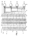
- an analog-to-binary converter 10 of the prior art adapted to convert an analog voltage signal Vi to a five-bit binary code signal of equivalent magnitude.
- the converter 10 comprises an analog-to-thermometer code converter 11, a thermometer-to-binary encoder 16, and a set of latch pipelines 18 coupling the output of the code converter 11 to the input of the encoder 16.
- the analog-to-thermometer code conversion circuit 11 comprises a set of sixteen comparators 12 and a voltage divider network 14.
- the analog voltage signal Vi is applied to a non-inverting input of each of the comparators 12 while a reference voltage Vref is applied to one end of the voltage divider network 14, the other end being grounded, thereby producing a series of progressively lower reference voltage quantum levels each of which is applied to an inverting input of a corresponding comparator 12.
- Each comparator 12 includes a difference amplifier having an output which saturates to a high (1) logic level output state if the input voltage is sufficiently higher than its voltage reference level or saturates to a low (0) logic level output state if the input voltage is sufficiently lower than its reference voltage.
- the outputs of the 1st through the 5th comparators (T1-T5) will all be high while the outputs of the 6th through the 16th comparator (T6-T16) will all be low.
- the outputs (T1 through T16) of all of the comparators 12 thus collectively appear as a 16-bit thermometer code representing the magnitude of the input voltage Vi as any one of seventeen discrete numbers from 0 to 16 inclusive.
- thermometer code output of the converter circuit 11 is latched onto the input of the encoding circuit 16 on receipt of a series of clock (CLK) signals by the latches of latch pipelines 18.
- the encoding circuit 16, which converts the thermometer code to a more compact and useful 5-bit binary code, comprises a set of AND gates 20 and a set of OR gates 22, one such AND gate corresponding to each thermometer code input bit and one such OR gate corresponding to each binary code output bit.
- Each thermometer code bit output of a corresponding latch pipeline 18 is applied to a non-inverting input of the corresponding AND gate 20 and to an inverting input of the AND gate 20 associated with the next lower order thermometer code bit, if any.
- the inverting input of the AND gate associated with the highest thermometer code bit T16 is grounded.
- the outputs of the sixteen AND gates 20 are connected to inputs of the OR gates 22 such that the output of one OR gate 22 comprises the first (rightmost) bit B1 of the binary code corresponding to the thermometer code appearing at the conversion circuit input, while the outputs of the other OR gates comprise the second through the fifth bits B2-B5 of the binary code.
- the AND gates 20 and OR gates 22 are interconnected to effect the following Boolean relations between the bits of the thermometer and binary codes, where the "*" symbol represents an AND function, the "+” symbol represents an OR function, and the "/" symbol preceding a bit reference character indicates a NOT function:
- thermometer code While latch pipelines 18 stabilize the individual converter 11 output bits, they do not prevent out-of-sequence errors in the thermometer code applied to the encoder 16 input.
- an out-of-sequence error one or more lower order bits of the thermometer code are in a 0 state while one or more higher order bits are in a 1 state.
- the 8-bit 00100111 thermometer code contains an out-of-sequence error.
- the higher order bit in the sixth position from the right is in the 1 state while two lower order bits bit in the 4th and 5th positions from the right are in the 0 state.
- This type of error can occur in an analog-to-thermometer code converter 11 when the frequency of the analog input signal Vi is high and the switching speeds or comparators 12 or the thresholds of latches 18 are not suitably matched.
- Vi changes rapidly from a high to a low value, the output of a lower order, relatively fast, comparator 12 may drop below the threshold of the first latch of its corresponding latch pipeline 18 before the output of a higher order, relatively slower, converter drops below the threshold of its corresponding pipeline's first latch. If the CLK signal clocks the latches 18 after the output of a lower order comparator 12 drops below its corresponding latch input 18 threshold, but before the output of the higher order converter drops below its corresponding latch input, an out-of-sequence error results. An out-of-sequence error can also occur when the input signal Vi rapidly increases.
- thermometer code containing an out-of-sequence error is passed on to the input of the thermometer-to-binary code converter 16 and the resulting binary code output of the converter bears little relation to the actual sample voltage Vi magnitude at the moment of sampling.
- the actual magnitude of the voltage Vi is likely to be between the value of the highest order in-sequence bit in a 1 state and the highest order out-of-sequence bit in a 1 state.
- the magnitude of the voltage Vi which produced an out-of-sequence thermometer code 0000000010001111 is most likely to be between 4 and 8.
- an "ideal" approximation of the particular magnitude of a sampled voltage producing a out-of-sequence error is obtained by simply counting the bits in the 1 state in the out-of-sequence thermometer code.
- the magnitude of Vi which would produce the example out-of-sequence thermometer code is most likely to be 5 since there are five logic level 1 bits in the code.
- the resulting 5-bit binary code output would be 01100, a decimal 12, for a deviation from the ideal approximation of 7.
- the deviation of the output of the encoder circuit 16 of FIG. 1 from the ideal approximation will always be positive and can be much larger. For instance, if the out-of-sequence thermometer code were 1011111111111111, the resulting binary code would be 11110 (decimal 30) when the ideal binary output code should be 01111 (decimal 15), a deviation from ideal of 15.
- thermometer-to-binary encoder 16 can be constructed by rearranging the connections of the outputs of the AND gates 20 and the inputs of the OR gates 22 in such a fashion as to make the outputs of the OR gates form a Gray-code equivalent in value to the thermometer code input.
- This encoder can then be fed through a Gray-to-binary encoder to complete the thermometer to binary conversion.
- the designs of such binary-to-Gray and Gray-to-binary encoders are well known in the art. Using such a thermometer-to-Gray-to-binary encoder reduces, but does not eliminate, encoding errors resulting from out-of-sequence thermometer code inputs.
- thermometer-to-Gray-to-binary encoder's output The error between the thermometer-to-Gray-to-binary encoder's output and the "ideal" approximations can be shown to appear somewhat random in nature (i.e., both positive and negative) and is limited to less than three times the span of the out-of-sequence error in the thermometer code input.
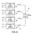
- an encoder 30, depicted in block diagram form is adapted to convert a first set of I digital signals, representing an I-bit thermometer code, into a second set of digital signals representing a corresponding binary code, with the output binary code exhibiting minimal deviation from the ideal approximation result when the input thermometer code contains an out-of-sequence error.
- the number of bits (I) of the thermometer code is 64, the bits of the code being labeled from T1 to T64 in order of their relative magnitude, the lowest order bit being T1.
- thermometer code signals are grouped into J subsets of K signals each, and each signal subset is applied as an input to a separate one of J thermometer-to-binary encoder stages 32, each comprising either a thermometer-to-binary encoder or a thermometer-to-Gray-to-binary encoder as described above.
- the integer J is 4 and the integer K is 16 so that there are 4 encoder stages 32, each converting a 16-bit thermometer code to a 5-bit binary code.
- the lowest order bit T1 of the 64-bit thermometer code is applied as a lowest order bit of the 16 bit thermometer code input of a first encoder stage 34.
- next 3 lowest order bits (bits T2-T4) of the 64-bit thermometer code are applied as the lowest order input bits to the second through the fourth encoder stages 36, 38 and 40 respectively.
- the next set of four lowest order bits (bits 5 through 8) of the 64-bit thermometer code are applied as the next lowest order input bits of the 16-bit thermometer code input to the first through the fourth encoder stages 32, respectively.
- the remaining progressively higher order bits of the 64-bit thermometer code are also grouped and applied as progressively higher order input bits to the encoder stages 32 such that the Nth encoder stage, where N is an integer from 1 through J (e.g. 4), has as its input a K-bit (e.g. 16-bit) thermometer code, comprising the Nth lowest order bit of the I-bit (e.g. 64-bit) thermometer code and every Jth (4th) bit thereafter in ascending order.
- K-bit e.g. 16-bit
- each encoder stage 32 has a five-bit binary output code similar to that of Table II above.
- the five-bit binary code output of each encoder stage is applied as an input to a summer 42 which generates as its output a seven-bit binary code representing the sum of the binary code outputs of encoders 32, which sum can range from 0 to 64.
- Circuits capable of performing the function of summer 42 are well known in the art and are not further detailed herein.
- thermometer code input to encoding circuit 30 represented the decimal number 21
- the 21 lowest order bits of the code would be high and the 43 higher order bits would be low.
- the 16-bit thermometer code input to the first encoder stage 34 would be 0000000000111111 (a decimal 6)
- the thermometer code inputs to the second, third and fourth encoder stages 36, 38, and 40 would all be 0000000000011111 (a decimal 5).
- the first encoder stage 34 would then convert its thermometer code input to a binary equivalent of decimal 6 while the other encoder stages would convert their thermometer code inputs to the binary equivalent of decimal 5.
- Summer 42 would then sum the four encoder stage 32 outputs to produce the 7-bit binary equivalent of decimal 21, 0010101.
- thermometer-to-Gray-to-binary or thermometer-to-binary code converter By grouping the bits of the I-bit thermometer code into subsets, separately encoding each subset, and summing the binary code output of each encoder stage 32 as described hereinabove, the deviation of the sum from the ideal approximation of an out-of-sequence thermometer code is reduced over that which would typically be produced by a single stage 64-bit thermometer-to-Gray-to-binary or thermometer-to-binary code converter. For instance, if the 64-bit thermometer code input was 00...001000111111111111, the thermometer code inputs to the first, second and third encoder stages 32 would all be 00...00111 (a decimal 3), while the input to the fourth encoder stage would be 00...001111 (a decimal 4).
- thermometer code subsets contain an out-of-sequence error.
- the output of the summer 42 would be the binary equivalent of a decimal 13 which is the ideal approximation corresponding to the out-of-sequence thermometer code since there are thirteen logic level 1 bits in the thermometer code. If such an out-of-sequence thermometer code were applied to a single stage 64-bit thermometer-to-binary encoder, similar in design to the encoder of FIG. 1 but having 64 rather than 16 inputs, the output of the encoder would be 00111000 (a decimal 28), a deviation of 15 from the ideal approximation.
- thermometer-to-Gray-to-binary encoder the output of the encoder would 0010011 (a decimal 19), a deviation of 6 from the ideal approximation.
- the span of the out-of-sequence error in the thermometer code 00...001000111111111 i.e., the number of intervening bits between the highest order 1 bit and the highest order in-sequence 1 bit in the thermometer code, is 3.
- the input to each encoder stage 32 will be free of out-of-sequence errors and the output of summer 42 will always equal the ideal approximation value of an out-of-sequence thermometer code input.
- the output of a single stage prior art encoding system will always differ from the ideal approximation value, often by a substantial amount as illustrated hereinabove.
- thermometer code inputs to encoder stages 32 may also contain an out-of-sequence error.
- span of the error in the K-bit thermometer code input to any one encoder stage 32 will be smaller than the span in the error in the I-bit thermometer code.
- the spans of the out-of-sequence errors in the K-bit thermometer codes will be at most the span of the error in the I-bit thermometer code divided by J.
- thermometer-to-Gray-to-binary encoders provides an advantage over use of direct thermometer-to-binary encoders as encoders 32 of FIG. 2. Since the errors in the outputs of the thermometer-to-Gray-to-binary encoders resulting from an out-of-sequence input thermometer code tend to be randomly distributed, the errors will tend to cancel one another when the encoder stage outputs are summed. The difference between the ideal approximation value of an out-of-sequence thermometer code and the output of the summer 42 is on the average reduced by a factor of the square root of J over the difference between the ideal and the actual output of a single stage encoder circuit of the prior art.
- thermometer-to-Gray-to binary encoders in the circuit of FIG. 2 will produce an output which on the average deviates from the ideal approximation by roughly half the amount by which the output of a 64-bit, single stage thermometer-to-binary encoder circuit deviates from the ideal approximation.
- thermometer code sizes (I) and/or other numbers (J) of encoder stages may be utilized in a similar fashion according to the present invention.
- encoder stages 32 comprising thermometer-to-Gray-to-binary encoders or thermometer-to-binary encoders of the type illustrated in FIG.
- thermometer-to-binary encoders may be used and are particularly advantageous if their out-of-sequence output errors are limited and tend to cancel one another.
- half of the encoders 32 are thermometer-to-binary encoders as in FIG. 1 and the other half are similarly constructed but using inverted logic whereby the errors from the first half will always be positive and the errors from the second half will always be negative, the errors will tend to cancel.
Claims (4)
- Procédé de conversion d'un code thermométrique d'entrée en un code binaire de sortie correspondant, chaque bit du code thermométrique d'entrée étant représenté par l'état d'un signal distinct dans un ensemble de signaux numériques, le procédé comprenant les étapes de :(a) regrouper les signaux numériques en sous- ensembles sélectionnés, chacun représentant un code thermométrique supplémentaire, les signaux numériques, tels que regroupés en sous- ensembles, représentant des bits espacés dans le code thermométrique d'entrée par un intervalle prédéterminé ;(b) convertir chaque code thermométrique des sous- ensembles de signaux en un code binaire correspondant ; et(c) ajouter les codes binaires représentant chaque sous- ensemble de signaux pour produire le code binaire de sortie.
- Procédé selon la revendication 1, caractérisé en ce que l'étape (a) comporte le regroupement des signaux numériques de codes thermométriques d'entrée en J sous- ensembles, chaque Nième sous- ensemble comprenant le Nième signal parmi les signaux numériques de codes thermométriques d'entrée, et chaque Jième signal numérique qui le suit.
- Procédé selon la revendication 3, caractérisé en ce que l'étape (b) comporte les sous étapes de :(d) convertir chaque code thermométrique des sous- ensembles de signaux en un code Gray correspondant ; et(e) convertir chaque code Gray en code binaire pour l'ajouter lors de l'étape (c).
- Appareil de conversion d'un premier ensemble de I signaux électroniques numériques représentant un code thermométrique à I bits en un second ensemble de signaux électroniques numériques représentant un code binaire correspondant, dans lequel I est un entier sélectionné, caractérisé par :
des moyens pour grouper le premier ensemble de signaux en une pluralité (J) de premiers sous- ensembles de signaux, le Nième des premiers sous- ensembles de signaux comprenant le Nième signal du premier ensemble de signaux et chaque Jième signal qui le suit, chaque premier sous- ensemble de signaux représentant de ce fait un code thermométrique distinct ;
des moyens (34, 36, 38, 40) pour convertir chacun des premiers sous- ensembles de signaux en un troisième sous- ensemble de signaux électroniques numériques, représentant un code binaire correspondant au code thermométrique représenté par le premier sous- ensemble de signaux; ,
des moyens (42) pour ajouter chaque troisième sous- ensemble ensemble de signaux électroniques numériques pour produire le second ensemble de signaux électroniques numériques représentant le code binaire correspondant au code thermométrique à I bits.
Applications Claiming Priority (2)
| Application Number | Priority Date | Filing Date | Title |
|---|---|---|---|
| US784415 | 1985-10-04 | ||
| US06/784,415 US4586025A (en) | 1985-10-04 | 1985-10-04 | Error tolerant thermometer-to-binary encoder |
Publications (3)
| Publication Number | Publication Date |
|---|---|
| EP0221238A2 EP0221238A2 (fr) | 1987-05-13 |
| EP0221238A3 EP0221238A3 (en) | 1989-05-10 |
| EP0221238B1 true EP0221238B1 (fr) | 1992-09-09 |
Family
ID=25132401
Family Applications (1)
| Application Number | Title | Priority Date | Filing Date |
|---|---|---|---|
| EP86109119A Expired - Lifetime EP0221238B1 (fr) | 1985-10-04 | 1986-07-03 | Encodeur tolérant aux erreurs pour la conversion d'un code thermomètre en un code binaire |
Country Status (4)
| Country | Link |
|---|---|
| US (1) | US4586025A (fr) |
| EP (1) | EP0221238B1 (fr) |
| JP (1) | JPS6286919A (fr) |
| DE (1) | DE3686697T2 (fr) |
Cited By (2)
| Publication number | Priority date | Publication date | Assignee | Title |
|---|---|---|---|---|
| CN1322675C (zh) * | 2003-02-06 | 2007-06-20 | 印芬龙科技股份有限公司 | 用于转换温度计码的转换装置和方法 |
| CN104795109A (zh) * | 2014-01-22 | 2015-07-22 | 南亚科技股份有限公司 | 动态随机存取存储器与选择性地执行刷新操作的方法 |
Families Citing this family (35)
| Publication number | Priority date | Publication date | Assignee | Title |
|---|---|---|---|---|
| JPS6188619A (ja) * | 1984-09-28 | 1986-05-06 | シーメンス、アクチエンゲゼルシヤフト | D‐a変換器 |
| US4712087A (en) * | 1987-02-09 | 1987-12-08 | Tektronix, Inc. | Analog-to-digital converter error correction circuit |
| US4774498A (en) * | 1987-03-09 | 1988-09-27 | Tektronix, Inc. | Analog-to-digital converter with error checking and correction circuits |
| JPS6468130A (en) * | 1987-09-09 | 1989-03-14 | Mitsubishi Electric Corp | Semiconductor integrated circuit |
| NL8702903A (nl) * | 1987-12-03 | 1989-07-03 | Philips Nv | Werkwijze en inrichting voor het optekenen van informatie op een registratiedrager, alsmede een inrichting voor het uitlezen van de opgetekende informatie. |
| US4870417A (en) * | 1988-02-12 | 1989-09-26 | North American Philips Corporation, Signetics Division | Error correction circuit suitable for thermometer or circular code |
| US4884075A (en) * | 1988-05-19 | 1989-11-28 | Analog Devices, Inc. | Decoding circuit for flash-type analog-to-digital converter |
| US4897657A (en) * | 1988-06-13 | 1990-01-30 | Integrated Device Technology, Inc. | Analog-to-digital converter having error detection and correction |
| FR2638037B1 (fr) * | 1988-10-14 | 1994-04-08 | Thomson Hybrides Microondes | Convertisseur analogique-numerique parallele, a circuit de correction d'erreur |
| US5155489A (en) * | 1989-01-31 | 1992-10-13 | Zdzislaw Gulczynski | Segmented encoder and digital memory particularly for flash analog-to-digital converters |
| US5012246A (en) * | 1990-01-31 | 1991-04-30 | International Business Machines Corporation | BiCMOS analog-to-digital converter with minimized metastability |
| EP0533253B1 (fr) * | 1991-09-20 | 1996-07-10 | Philips Composants Et Semiconducteurs | Procédé de transcodage de données d'un code thermométrique, décodeur et convertisseur appliquant ce procédé |
| US5243348A (en) * | 1992-04-27 | 1993-09-07 | Motorola, Inc. | Partitioned digital encoder and method for encoding bit groups in parallel |
| JP2917095B2 (ja) * | 1993-07-08 | 1999-07-12 | テクトロニクス・インコーポレイテッド | サーモメータ・コード処理方法及び装置 |
| US5382955A (en) * | 1993-11-04 | 1995-01-17 | Tektronix, Inc. | Error tolerant thermometer-to-binary encoder |
| US5459466A (en) * | 1995-02-23 | 1995-10-17 | Tektronix, Inc. | Method and apparatus for converting a thermometer code to a gray code |
| JPH10173529A (ja) * | 1996-12-13 | 1998-06-26 | Sony Corp | アナログ/ディジタル変換回路 |
| JP2001502834A (ja) | 1997-12-19 | 2001-02-27 | ブリテッシュ エアロスペース パブリック リミテッド カンパニー | ニューラルネットワーク及びニューラルメモリ |
| DE69808798T2 (de) | 1997-12-19 | 2003-09-18 | Bae Systems Plc Farnborough | Digitales signalfilter unter verwendung von ungewichteten neuralen techniken |
| AU1769999A (en) | 1997-12-19 | 1999-07-12 | British Aerospace Public Limited Company | Weightless binary n-tuple thresholding hierarchies |
| EP1038215B9 (fr) | 1997-12-19 | 2003-12-03 | BAE SYSTEMS plc | Comparaison de valeur hamming pour reseaux binaires non ponderes |
| JP3339566B2 (ja) * | 1998-10-21 | 2002-10-28 | 日本電気株式会社 | サーモメトリック−バイナリコード変換方法および回路、それに使用されるエンコーダ素子回路 |
| US6188347B1 (en) * | 1999-07-12 | 2001-02-13 | National Instruments Corporation | Analog-to-digital conversion system and method with reduced sparkle codes |
| KR100677079B1 (ko) * | 1999-12-08 | 2007-02-01 | 삼성전자주식회사 | 조건 선택 인코더 및 그 인코딩 방법 |
| US6542104B1 (en) * | 2001-10-22 | 2003-04-01 | Santel Networks, Inc. | Method and apparatus for low power thermometer to binary coder |
| DE10200503A1 (de) * | 2002-01-09 | 2003-07-24 | Infineon Technologies Ag | Vorrichtung und Verfahren zum Umwandeln von Thermometer-Code in Binär-Code und Analog-/Digital-Wandler |
| JPWO2004086628A1 (ja) * | 2003-03-25 | 2006-06-29 | 富士通株式会社 | エンコーダ回路及びa/d変換回路 |
| KR100787078B1 (ko) | 2005-03-09 | 2007-12-21 | 후지쯔 가부시끼가이샤 | 인코더 회로 및 a/d 변환 회로 |
| US7541961B1 (en) * | 2008-04-01 | 2009-06-02 | Broadcom Corporation | High speed, low power all CMOS thermometer-to-binary demultiplexer |
| US7675440B1 (en) | 2008-04-28 | 2010-03-09 | Altera Corporation | Thermometer-code-to-binary encoders |
| US8031011B2 (en) * | 2008-06-27 | 2011-10-04 | Altera Corporation | Digitally controlled oscillators |
| JP5450126B2 (ja) * | 2010-01-28 | 2014-03-26 | ルネサスエレクトロニクス株式会社 | Adpll、半導体装置及び携帯電話機 |
| JP5500651B2 (ja) | 2010-12-28 | 2014-05-21 | キャタピラー エス エー アール エル | 流体圧回路の制御装置および作業機械 |
| JP6572290B2 (ja) * | 2017-11-22 | 2019-09-04 | ファナック株式会社 | 電子機器の異常検出装置 |
| CN109238315A (zh) * | 2018-07-04 | 2019-01-18 | 西安电子科技大学 | 一种温度计码编码器及电路 |
Family Cites Families (6)
| Publication number | Priority date | Publication date | Assignee | Title |
|---|---|---|---|---|
| US3806915A (en) * | 1972-09-05 | 1974-04-23 | Us Navy | Multithreshold analog to digital converter |
| US4069479A (en) * | 1976-03-03 | 1978-01-17 | The United States Of America As Represented By The Secretary Of Commerce | High speed, wide dynamic range analog-to-digital conversion |
| DE2652484A1 (de) * | 1976-11-18 | 1978-05-24 | Fouad Moustafa Dipl Ing Fahmy | Verfahren zur durchfuehrung einer analog-digital-umsetzung elektrischer groessen |
| US4498177A (en) * | 1982-08-30 | 1985-02-05 | Sperry Corporation | M Out of N code checker circuit |
| JPS60146528A (ja) * | 1984-01-11 | 1985-08-02 | Nec Corp | A/d変換回路 |
| JPS60177729A (ja) * | 1984-02-23 | 1985-09-11 | Matsushita Electric Ind Co Ltd | 並列形アナログ・デイジタル変換器 |
-
1985
- 1985-10-04 US US06/784,415 patent/US4586025A/en not_active Expired - Lifetime
-
1986
- 1986-07-03 EP EP86109119A patent/EP0221238B1/fr not_active Expired - Lifetime
- 1986-07-03 DE DE8686109119T patent/DE3686697T2/de not_active Expired - Fee Related
- 1986-09-30 JP JP61233115A patent/JPS6286919A/ja active Granted
Cited By (3)
| Publication number | Priority date | Publication date | Assignee | Title |
|---|---|---|---|---|
| CN1322675C (zh) * | 2003-02-06 | 2007-06-20 | 印芬龙科技股份有限公司 | 用于转换温度计码的转换装置和方法 |
| CN104795109A (zh) * | 2014-01-22 | 2015-07-22 | 南亚科技股份有限公司 | 动态随机存取存储器与选择性地执行刷新操作的方法 |
| CN104795109B (zh) * | 2014-01-22 | 2018-06-08 | 南亚科技股份有限公司 | 动态随机存取存储器与选择性地执行刷新操作的方法 |
Also Published As
| Publication number | Publication date |
|---|---|
| US4586025A (en) | 1986-04-29 |
| EP0221238A3 (en) | 1989-05-10 |
| DE3686697T2 (de) | 1993-04-08 |
| JPS6286919A (ja) | 1987-04-21 |
| JPH0253974B2 (fr) | 1990-11-20 |
| EP0221238A2 (fr) | 1987-05-13 |
| DE3686697D1 (de) | 1992-10-15 |
Similar Documents
| Publication | Publication Date | Title |
|---|---|---|
| EP0221238B1 (fr) | Encodeur tolérant aux erreurs pour la conversion d'un code thermomètre en un code binaire | |
| US4733220A (en) | Thermometer-to-adjacent bindary encoder | |
| US5072221A (en) | Error limiting analog to digital converter | |
| US5382955A (en) | Error tolerant thermometer-to-binary encoder | |
| US5243347A (en) | Monotonic current/resistor digital-to-analog converter and method of operation | |
| EP0493443B1 (fr) | CONVERTISSEUR ANALOGIQUE-NUMERIQUE PARALLELE UTILISANT 2?n-1 COMPARATEURS | |
| US5283580A (en) | Current/resistor digital-to-analog converter having enhanced integral linearity and method of operation | |
| CA1175148A (fr) | Generateur de tremblottements numeriques de decalage | |
| US6433725B1 (en) | High speed analog-to-digital converter | |
| US3893102A (en) | Digital-to-analog converter using differently decoded bit groups | |
| GB2223369A (en) | Analogue-to-digital converters | |
| EP0217009A2 (fr) | Encodeur pour la conversion d'un code thermomètre en un code binaire adjacent | |
| CN110034761B (zh) | 压控振荡器型模数转换器数字输出转二进制码的编码电路 | |
| JPH0232813B2 (fr) | ||
| US20030201924A1 (en) | Digital-to-analog converter | |
| US5455583A (en) | Combined conventional/neural network analog to digital converter | |
| US4665382A (en) | Analog-to-digital conversion | |
| Bellavin et al. | Study of Bubble Errors Conversion in a Modified ROM Encoder | |
| JP2917095B2 (ja) | サーモメータ・コード処理方法及び装置 | |
| KR100301041B1 (ko) | 플래쉬방식아날로그/디지털변환장치 | |
| US6816098B2 (en) | High-speed oversampling modulator device | |
| CN210274034U (zh) | 一种高精度dac | |
| US5099238A (en) | Parallel analog to digital converter | |
| JP2638802B2 (ja) | 並列型a/d変換器 | |
| Bryant et al. | Data converter architectures |
Legal Events
| Date | Code | Title | Description |
|---|---|---|---|
| PUAI | Public reference made under article 153(3) epc to a published international application that has entered the european phase |
Free format text: ORIGINAL CODE: 0009012 |
|
| AK | Designated contracting states |
Kind code of ref document: A2 Designated state(s): DE FR GB NL |
|
| PUAL | Search report despatched |
Free format text: ORIGINAL CODE: 0009013 |
|
| AK | Designated contracting states |
Kind code of ref document: A3 Designated state(s): DE FR GB NL |
|
| 17P | Request for examination filed |
Effective date: 19890822 |
|
| 17Q | First examination report despatched |
Effective date: 19901004 |
|
| GRAA | (expected) grant |
Free format text: ORIGINAL CODE: 0009210 |
|
| AK | Designated contracting states |
Kind code of ref document: B1 Designated state(s): DE FR GB NL |
|
| RAP2 | Party data changed (patent owner data changed or rights of a patent transferred) |
Owner name: TEKTRONIX, INC. |
|
| REF | Corresponds to: |
Ref document number: 3686697 Country of ref document: DE Date of ref document: 19921015 |
|
| RAP2 | Party data changed (patent owner data changed or rights of a patent transferred) |
Owner name: TEKTRONIX, INC. |
|
| ET | Fr: translation filed | ||
| PGFP | Annual fee paid to national office [announced via postgrant information from national office to epo] |
Ref country code: GB Payment date: 19930615 Year of fee payment: 8 |
|
| PGFP | Annual fee paid to national office [announced via postgrant information from national office to epo] |
Ref country code: DE Payment date: 19930621 Year of fee payment: 8 |
|
| PLBE | No opposition filed within time limit |
Free format text: ORIGINAL CODE: 0009261 |
|
| STAA | Information on the status of an ep patent application or granted ep patent |
Free format text: STATUS: NO OPPOSITION FILED WITHIN TIME LIMIT |
|
| 26N | No opposition filed | ||
| PG25 | Lapsed in a contracting state [announced via postgrant information from national office to epo] |
Ref country code: NL Effective date: 19940201 |
|
| NLV4 | Nl: lapsed or anulled due to non-payment of the annual fee | ||
| PG25 | Lapsed in a contracting state [announced via postgrant information from national office to epo] |
Ref country code: FR Effective date: 19940331 |
|
| REG | Reference to a national code |
Ref country code: FR Ref legal event code: ST |
|
| PG25 | Lapsed in a contracting state [announced via postgrant information from national office to epo] |
Ref country code: GB Effective date: 19940703 |
|
| GBPC | Gb: european patent ceased through non-payment of renewal fee |
Effective date: 19940703 |
|
| PG25 | Lapsed in a contracting state [announced via postgrant information from national office to epo] |
Ref country code: DE Effective date: 19950401 |