EP0219890A1 - Dispositif de transfert - Google Patents
Dispositif de transfert Download PDFInfo
- Publication number
- EP0219890A1 EP0219890A1 EP86201433A EP86201433A EP0219890A1 EP 0219890 A1 EP0219890 A1 EP 0219890A1 EP 86201433 A EP86201433 A EP 86201433A EP 86201433 A EP86201433 A EP 86201433A EP 0219890 A1 EP0219890 A1 EP 0219890A1
- Authority
- EP
- European Patent Office
- Prior art keywords
- shaft
- knife
- knives
- lower knife
- cut
- Prior art date
- Legal status (The legal status is an assumption and is not a legal conclusion. Google has not performed a legal analysis and makes no representation as to the accuracy of the status listed.)
- Granted
Links
- 238000006073 displacement reaction Methods 0.000 claims description 4
- 239000011888 foil Substances 0.000 claims description 3
- 238000005520 cutting process Methods 0.000 abstract description 15
- 238000004519 manufacturing process Methods 0.000 description 5
- 230000006835 compression Effects 0.000 description 2
- 238000007906 compression Methods 0.000 description 2
- 239000000463 material Substances 0.000 description 2
- 239000000428 dust Substances 0.000 description 1
- 239000004744 fabric Substances 0.000 description 1
- 229910052751 metal Inorganic materials 0.000 description 1
- 239000002184 metal Substances 0.000 description 1
- 150000002739 metals Chemical class 0.000 description 1
- 238000000034 method Methods 0.000 description 1
- 239000000123 paper Substances 0.000 description 1
Images

Classifications
-
- B—PERFORMING OPERATIONS; TRANSPORTING
- B26—HAND CUTTING TOOLS; CUTTING; SEVERING
- B26D—CUTTING; DETAILS COMMON TO MACHINES FOR PERFORATING, PUNCHING, CUTTING-OUT, STAMPING-OUT OR SEVERING
- B26D7/00—Details of apparatus for cutting, cutting-out, stamping-out, punching, perforating, or severing by means other than cutting
- B26D7/26—Means for mounting or adjusting the cutting member; Means for adjusting the stroke of the cutting member
- B26D7/2628—Means for adjusting the position of the cutting member
- B26D7/2635—Means for adjusting the position of the cutting member for circular cutters
-
- Y—GENERAL TAGGING OF NEW TECHNOLOGICAL DEVELOPMENTS; GENERAL TAGGING OF CROSS-SECTIONAL TECHNOLOGIES SPANNING OVER SEVERAL SECTIONS OF THE IPC; TECHNICAL SUBJECTS COVERED BY FORMER USPC CROSS-REFERENCE ART COLLECTIONS [XRACs] AND DIGESTS
- Y10—TECHNICAL SUBJECTS COVERED BY FORMER USPC
- Y10T—TECHNICAL SUBJECTS COVERED BY FORMER US CLASSIFICATION
- Y10T83/00—Cutting
- Y10T83/647—With means to convey work relative to tool station
- Y10T83/6584—Cut made parallel to direction of and during work movement
- Y10T83/6587—Including plural, laterally spaced tools
- Y10T83/6588—Tools mounted on common tool support
- Y10T83/659—Tools axially shiftable on support
-
- Y—GENERAL TAGGING OF NEW TECHNOLOGICAL DEVELOPMENTS; GENERAL TAGGING OF CROSS-SECTIONAL TECHNOLOGIES SPANNING OVER SEVERAL SECTIONS OF THE IPC; TECHNICAL SUBJECTS COVERED BY FORMER USPC CROSS-REFERENCE ART COLLECTIONS [XRACs] AND DIGESTS
- Y10—TECHNICAL SUBJECTS COVERED BY FORMER USPC
- Y10T—TECHNICAL SUBJECTS COVERED BY FORMER US CLASSIFICATION
- Y10T83/00—Cutting
- Y10T83/768—Rotatable disc tool pair or tool and carrier
- Y10T83/7809—Tool pair comprises rotatable tools
- Y10T83/7822—Tool pair axially shiftable
- Y10T83/7826—With shifting mechanism for at least one element of tool pair
-
- Y—GENERAL TAGGING OF NEW TECHNOLOGICAL DEVELOPMENTS; GENERAL TAGGING OF CROSS-SECTIONAL TECHNOLOGIES SPANNING OVER SEVERAL SECTIONS OF THE IPC; TECHNICAL SUBJECTS COVERED BY FORMER USPC CROSS-REFERENCE ART COLLECTIONS [XRACs] AND DIGESTS
- Y10—TECHNICAL SUBJECTS COVERED BY FORMER USPC
- Y10T—TECHNICAL SUBJECTS COVERED BY FORMER US CLASSIFICATION
- Y10T83/00—Cutting
- Y10T83/768—Rotatable disc tool pair or tool and carrier
- Y10T83/7809—Tool pair comprises rotatable tools
- Y10T83/7847—Tool element axially shiftable
-
- Y—GENERAL TAGGING OF NEW TECHNOLOGICAL DEVELOPMENTS; GENERAL TAGGING OF CROSS-SECTIONAL TECHNOLOGIES SPANNING OVER SEVERAL SECTIONS OF THE IPC; TECHNICAL SUBJECTS COVERED BY FORMER USPC CROSS-REFERENCE ART COLLECTIONS [XRACs] AND DIGESTS
- Y10—TECHNICAL SUBJECTS COVERED BY FORMER USPC
- Y10T—TECHNICAL SUBJECTS COVERED BY FORMER US CLASSIFICATION
- Y10T83/00—Cutting
- Y10T83/768—Rotatable disc tool pair or tool and carrier
- Y10T83/7872—Tool element mounted for adjustment
- Y10T83/7876—Plural, axially spaced tool elements
Definitions
- the present invention relates to a device for changing the position of knives, in particular of lower knives for wrapped cutting when slitting paper, foil, tissue or similar web-like material with annular lower knives pushed onto at least one shaft or holders for these lower knives.
- the end processor of the web to be cut often requests webs of different widths, which is why there is a need to cut a relatively wide web during one production process, for example into relatively wide webs and during another production process into relatively narrow webs.
- These cut webs are usually wound up into rolls, for example to be sent to the respective end processor of these railways in a simple and convenient manner.
- the changing requirements of the end processor mean for those who have to subdivide a relatively wide web into individual webs that the facility available to them must be changed accordingly. This process is usually referred to as "positioning”.
- EP-A 96 026 (WO 83/02083) ver follows the goal of widening a hub. However, this aim is not aimed at by the proposed invention. A widening of knife hubs is not up for discussion in the proposed invention. This also applies to French patent application 23 40 170.
- the task is to propose a simple and smooth-running device for moving the knives or their holders, in particular those knives or holders for the so-called lower knife, in particular in the event that the lower knife is at least partially from the is wrapped into a cutting web.
- At least one radial bore is incorporated into each support of an undercutter or per undercutter in the shaft supporting the undercutter or supports, the exit points of this radial bore or these radial bores are arranged within the axial region of the shaft, which also at in the longitudinal direction of the shaft slight displacement of the holder or the lower knife is constantly covered by this holder or the lower knife, the exit points of the bores are positioned in the upper half of the shaft when the shaft is at a standstill, a positioning device which enables this positioning and can be brought into engagement a feed line for introducing pressure medium into the radial bores is provided.
- the present invention makes it possible to make the lower knife in the radial direction with respect to it supporting shaft within the game due to the manufacturing so far that it can be easily moved in the axial direction of the shaft.
- This makes it possible to move relatively heavy lower knives, in particular so-called cutting sleeves, from one position to another with ease.
- This in turn makes it possible to switch the entire device in question from one type of production to another in a simple and quick manner, ie for example from a width of strips to be cut to another.
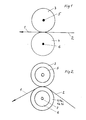
- a web 2 to be cut into several strips 1 runs through a pair of knives.
- Each pair of knives comprises an upper knife 3 and at least one lower knife 4.
- the upper knife (s) 3 is / are fastened on the shaft 5, while the lower knife (s) 4 are fastened on a shaft 6.
- Each of the shafts 5 or 6 is rotatably mounted in a correspondingly designed machine frame and can also be driven.
- the upper knives 3 can be displaced along the shaft 5 — that is, in the viewing direction of FIG. 1 — and the lower knives 4 along the shaft 6 as required. This shift can be relatively slight, especially if there are several intersecting points per undercutter.
- bottom cutters can be designed in the form of so-called cutting sleeves, with each cutting sleeve containing a multiplicity of cutting edges.
- One and the same upper knife can optionally work together with each of these edges, so that it is often necessary in so-called format changes to move the upper knife by a relatively wide axial extent, while the lower knife only by a much shorter length, in order to enable this that the upper knife can work with another cutting edge, a so-called cutting groove, than before.
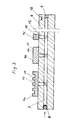
- a plurality of lower knives 4a, 4b, 4c etc. can be arranged next to one another on each shaft 6.
- at least one axial bore 7 is machined into the shaft 6.
- a ball valve 8 At one end of the bore 7 there is a ball valve 8, the other end is closed by a screw 9.
- Radial bores 10, 11 and 12 open into the bore 7, the radially outer ends of which represent exit points from which the compressed air blown in via the ball valve 8 can escape. These exit points are designated 13, 14 and 15.
- the exit points 13, 14 and 15 in FIG. 3 are arranged approximately in the middle of the respective lower knife, so that even if the respective associated lower knife should be displaced within certain limits in the axial direction of the shaft 6, the respective exit point of the respective lower knife is constantly covered. In other words, this means that the respective lower knife can only be displaced relative to the shaft 6 to such an extent that this lower knife just barely covers the respective outlet opening.
- the radial bores 10, 11 and 12 are incorporated in the shaft 6 such that they come to rest in the upper half 16 of this shaft when the shaft is at a standstill with a sectional representation of the shaft.
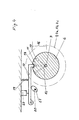
- a positioning device is provided which enables the shaft 6 to be stopped in an easily possible manner immediately before the respective positioning of the lower knives 4 in such a way that the bores 10, 11 and 12 come to lie in the upper half 16.
- the positioning device consists, for example, of a pawl 17 which can engage in a corresponding recess or groove 18 in the shaft 6.
- the pawl 17 can be snapped into the bore 18 with the aid of a compression spring 19.
- a switch 23 prevents the machine from starting in the event that the pawl 17 blocks the rotation of the shaft 6.
- the bore 18 is preferably made at one end of the shaft 6 so that most of the shaft 6 remains free to position the lower knife thereon.
- the knives or knife bushings can be shifted along the shaft 6 by both small and long distances, as long as only the respective knife covers the hole assigned to this knife. Due to the pressure medium emerging from the respective bore, in particular compressed air, the respective knife or the respective knife sleeve is raised by a small amount relative to the knife shaft and is able to slide on a thin cushion of pressure medium inserted between the shaft and knife. For this, it is not absolutely necessary to work special chambers into the inside of the knife, the knife sleeve or the knife holder for receiving the pressure medium. For example, it is also possible to use the knife, the lower knife sleeve or the knife holder to raise within the game that is already predetermined by the mechanical production of the machine parts involved.
- the respective upper knife work together with one edge during a certain cutting process and with another edge of the respective lower knife or the respective lower knife sleeve during another cutting process.
- This either increases the service life of the lower knife bushing or, with simultaneous displacement of the respective lower knife bushing relative to the upper knife, makes it easier to produce strips of different widths from materials to be cut from a web.
- the present invention aids in the changeover from one format to be cut and possibly wound up to another.
- any cutting dust that may accumulate between the knife shaft and knife holder can be blown out of the device by the pressure medium, especially when using compressed air.
- each separate lower knife can be moved a separate supply of pressure medium z. B. to assign compressed air so that only this one lower knife or its holder can be axially displaced relative to the shaft 6, while the other lower knives on the shaft 6 maintain their position.
Landscapes
- Life Sciences & Earth Sciences (AREA)
- Forests & Forestry (AREA)
- Engineering & Computer Science (AREA)
- Mechanical Engineering (AREA)
- Nonmetal Cutting Devices (AREA)
- Treatment Of Fiber Materials (AREA)
- Details Of Cutting Devices (AREA)
- Perforating, Stamping-Out Or Severing By Means Other Than Cutting (AREA)
Applications Claiming Priority (2)
| Application Number | Priority Date | Filing Date | Title |
|---|---|---|---|
| DE3533739 | 1985-09-21 | ||
| DE19853533739 DE3533739A1 (de) | 1985-09-21 | 1985-09-21 | Verschiebe-einrichtung |
Publications (2)
| Publication Number | Publication Date |
|---|---|
| EP0219890A1 true EP0219890A1 (fr) | 1987-04-29 |
| EP0219890B1 EP0219890B1 (fr) | 1989-04-05 |
Family
ID=6281597
Family Applications (1)
| Application Number | Title | Priority Date | Filing Date |
|---|---|---|---|
| EP86201433A Expired EP0219890B1 (fr) | 1985-09-21 | 1986-08-18 | Dispositif de transfert |
Country Status (6)
| Country | Link |
|---|---|
| US (1) | US4759249A (fr) |
| EP (1) | EP0219890B1 (fr) |
| JP (1) | JPS62130195A (fr) |
| DE (2) | DE3533739A1 (fr) |
| ES (1) | ES2003102A6 (fr) |
| FI (1) | FI83049C (fr) |
Families Citing this family (15)
| Publication number | Priority date | Publication date | Assignee | Title |
|---|---|---|---|---|
| DE4002917A1 (de) * | 1990-02-01 | 1991-08-08 | Goebel Gmbh Maschf | Einrichtung zum haltern eines schneidwerkzeuges |
| US5386950A (en) * | 1992-06-08 | 1995-02-07 | Abt; Richard | Apparatus and method for preparing individual wound rolls from a slitted web of material |
| US5562008A (en) * | 1995-03-20 | 1996-10-08 | Danieli Wean | Edge trimmer starter punch |
| GB2299046A (en) * | 1995-03-21 | 1996-09-25 | Nestle Sa | Ultrasonic cutting device |
| US6012372A (en) * | 1996-01-18 | 2000-01-11 | Laster; James E. | Adjustable arbor and cutting elements |
| US5871783A (en) | 1996-08-22 | 1999-02-16 | Mars, Incorporated | Apparatus for ultrasonically forming confectionery products |
| US5861185A (en) | 1996-08-22 | 1999-01-19 | Mars, Incorporated | Ultrasonic forming of confectionery products |
| US5871793A (en) | 1996-11-27 | 1999-02-16 | Mars Incorporated | Puffed cereal cakes |
| US5846584A (en) | 1997-04-30 | 1998-12-08 | Mars, Incorporated | Apparatus and method for forming cereal food products |
| US20020127310A1 (en) * | 1998-12-07 | 2002-09-12 | Capodieci Roberto A. | Cereal food product and method |
| US6368647B1 (en) | 1998-12-29 | 2002-04-09 | Mars, Incorporated | Ultrasonically activated continuous slitter apparatus and method |
| US6574944B2 (en) * | 2001-06-19 | 2003-06-10 | Mars Incorporated | Method and system for ultrasonic sealing of food product packaging |
| US6655948B2 (en) | 2001-08-31 | 2003-12-02 | Mars, Incorporated | System of ultrasonic processing of pre-baked food product |
| US6635292B2 (en) | 2001-10-26 | 2003-10-21 | Mars, Incorporated | Ultrasonic rotary forming of food products |
| US10639728B2 (en) * | 2016-04-19 | 2020-05-05 | Jdc, Inc. | Disposing device of shaft-body insertion objects |
Citations (6)
| Publication number | Priority date | Publication date | Assignee | Title |
|---|---|---|---|---|
| DE1038902B (de) * | 1954-02-02 | 1958-09-11 | Jagenberg Werke Ag | Laengsschneidevorrichtung an Rollenschneidemaschinen |
| DE1802305B1 (de) * | 1967-10-11 | 1970-07-16 | Masson Scott Thrissell Eng Ltd | Einstellvorrichtung fuer Laengsschneider |
| DE2126407B2 (de) * | 1971-05-27 | 1972-11-16 | Ungerer Geb. Dollinger, Irma, 7530 Pforzheim | Spannwelle fuer rotierende werkzeuge und fuehrungen |
| FR2340170A1 (fr) * | 1976-02-06 | 1977-09-02 | Metal Box Co Ltd | Mise en position, sur un arbre, d'un moyeu, notamment porte-outil |
| DE2756997A1 (de) * | 1976-12-30 | 1978-07-06 | Masson Scott Thrissell Eng Ltd | Pneumatische schneidwalze |
| WO1983002083A1 (fr) * | 1981-12-17 | 1983-06-23 | Spoerndli, Max | Dispositif de coupe |
Family Cites Families (2)
| Publication number | Priority date | Publication date | Assignee | Title |
|---|---|---|---|---|
| US3753517A (en) * | 1971-11-26 | 1973-08-21 | Teijin Ltd | Guide roll for filaments |
| SE417056B (sv) * | 1979-07-19 | 1981-02-23 | Alani Safwat David | Appliceringsenhet for epikutantest eller behandling |
-
1985
- 1985-09-21 DE DE19853533739 patent/DE3533739A1/de not_active Withdrawn
-
1986
- 1986-08-18 DE DE8686201433T patent/DE3662658D1/de not_active Expired
- 1986-08-18 EP EP86201433A patent/EP0219890B1/fr not_active Expired
- 1986-09-19 FI FI863806A patent/FI83049C/fi not_active IP Right Cessation
- 1986-09-19 ES ES8602019A patent/ES2003102A6/es not_active Expired
- 1986-09-22 JP JP61222269A patent/JPS62130195A/ja active Granted
- 1986-09-22 US US06/909,912 patent/US4759249A/en not_active Expired - Fee Related
Patent Citations (6)
| Publication number | Priority date | Publication date | Assignee | Title |
|---|---|---|---|---|
| DE1038902B (de) * | 1954-02-02 | 1958-09-11 | Jagenberg Werke Ag | Laengsschneidevorrichtung an Rollenschneidemaschinen |
| DE1802305B1 (de) * | 1967-10-11 | 1970-07-16 | Masson Scott Thrissell Eng Ltd | Einstellvorrichtung fuer Laengsschneider |
| DE2126407B2 (de) * | 1971-05-27 | 1972-11-16 | Ungerer Geb. Dollinger, Irma, 7530 Pforzheim | Spannwelle fuer rotierende werkzeuge und fuehrungen |
| FR2340170A1 (fr) * | 1976-02-06 | 1977-09-02 | Metal Box Co Ltd | Mise en position, sur un arbre, d'un moyeu, notamment porte-outil |
| DE2756997A1 (de) * | 1976-12-30 | 1978-07-06 | Masson Scott Thrissell Eng Ltd | Pneumatische schneidwalze |
| WO1983002083A1 (fr) * | 1981-12-17 | 1983-06-23 | Spoerndli, Max | Dispositif de coupe |
Also Published As
| Publication number | Publication date |
|---|---|
| FI83049B (fi) | 1991-02-15 |
| FI863806A0 (fi) | 1986-09-19 |
| ES2003102A6 (es) | 1988-10-16 |
| FI83049C (fi) | 1991-05-27 |
| JPS62130195A (ja) | 1987-06-12 |
| EP0219890B1 (fr) | 1989-04-05 |
| FI863806A (fi) | 1987-03-22 |
| JPH0215354B2 (fr) | 1990-04-11 |
| US4759249A (en) | 1988-07-26 |
| DE3533739A1 (de) | 1987-03-26 |
| DE3662658D1 (en) | 1989-05-11 |
Similar Documents
| Publication | Publication Date | Title |
|---|---|---|
| EP0219890B1 (fr) | Dispositif de transfert | |
| DE3031040C2 (fr) | ||
| DE3714662C2 (fr) | ||
| DE2436717A1 (de) | Schlitz- und falzvorrichtung fuer durchlaufende materialbahnen | |
| DE2701068A1 (de) | Schlitzvorrichtung fuer bahnenfoermiges material | |
| DE2600718B2 (de) | Vorrichtung zum Unterteilen von Flachmaterialbahnen in Längsstreifen von gewünschter Breite | |
| EP1065031A2 (fr) | Dispositif pour la perforation transversale d'une bande | |
| DE10356037A1 (de) | Schneid-Vorrichtung | |
| DE10047545B4 (de) | Schneid- und Transportwalze mit integrierter Schneidvorrichtung mit schwenkbaren Schneidflächen und Verfahren zum Schneiden von Materialbahnen mithilfe einer solchen Walze | |
| EP1415944A1 (fr) | Appareil pour l'ajustement de rouleaux de pression et/ou de lames de coupe dans une plieuse | |
| DE3634198A1 (de) | Querschneider | |
| DE3234904A1 (de) | Bandklebevorrichtung | |
| EP0792814A1 (fr) | Machine de déballage de rouleaux, spécialement de rouleaux de papier d'imprimerie | |
| EP0791549A2 (fr) | Méthode et dispositif pour enrouler une bande de matériau coupée en long | |
| DE2350580A1 (de) | Wechselvorrichtung fuer einhuellbahnen an verpackungsmaschinen | |
| DE3103958C2 (de) | Vorrichtung zum Abspalten eines Materialstreifens von einer bewegten Materialbahn | |
| DE2805211C3 (de) | Vorrichtung zum Längsschneiden von Materialbahnen | |
| DE3901854A1 (de) | Vorrichtung zum verbinden von materialbahnen | |
| DE60009421T2 (de) | Bandlegeeinheit zum Auftragen eines Bandes aus Verbundmaterial | |
| DE8527026U1 (de) | Verschiebe-Einrichtung | |
| DE60109975T2 (de) | Schneidemaschine für eine Vielzahl von Küchen- und/oder Toilettenpapierrollen | |
| DE2828427C2 (de) | Vorrichtung zum positiven Liefern von Faden an Rundstrickmaschinen | |
| DE60011271T2 (de) | Verfahren und vorrichtung im prozess des aufwickels einer papierbahn | |
| DE2706510C2 (de) | Stabeisenschere | |
| DE4425201C2 (de) | Verfahren und Vorrichtung zum Trennen einer Kunststoffwarenbahn in einer Rollenschneid- und Wickelmaschine |
Legal Events
| Date | Code | Title | Description |
|---|---|---|---|
| PUAI | Public reference made under article 153(3) epc to a published international application that has entered the european phase |
Free format text: ORIGINAL CODE: 0009012 |
|
| AK | Designated contracting states |
Kind code of ref document: A1 Designated state(s): BE CH DE FR GB IT LI NL SE |
|
| ITCL | It: translation for ep claims filed |
Representative=s name: BARZANO' E ZANARDO MILANO S.P.A. |
|
| 17P | Request for examination filed |
Effective date: 19870313 |
|
| EL | Fr: translation of claims filed | ||
| TCNL | Nl: translation of patent claims filed | ||
| 17Q | First examination report despatched |
Effective date: 19880511 |
|
| ITF | It: translation for a ep patent filed |
Owner name: BARZANO' E ZANARDO MILANO S.P.A. |
|
| GRAA | (expected) grant |
Free format text: ORIGINAL CODE: 0009210 |
|
| AK | Designated contracting states |
Kind code of ref document: B1 Designated state(s): BE CH DE FR GB IT LI NL SE |
|
| GBT | Gb: translation of ep patent filed (gb section 77(6)(a)/1977) | ||
| REF | Corresponds to: |
Ref document number: 3662658 Country of ref document: DE Date of ref document: 19890511 |
|
| ET | Fr: translation filed | ||
| PLBE | No opposition filed within time limit |
Free format text: ORIGINAL CODE: 0009261 |
|
| STAA | Information on the status of an ep patent application or granted ep patent |
Free format text: STATUS: NO OPPOSITION FILED WITHIN TIME LIMIT |
|
| 26N | No opposition filed | ||
| ITTA | It: last paid annual fee | ||
| EAL | Se: european patent in force in sweden |
Ref document number: 86201433.9 |
|
| PGFP | Annual fee paid to national office [announced via postgrant information from national office to epo] |
Ref country code: NL Payment date: 19970831 Year of fee payment: 12 |
|
| PGFP | Annual fee paid to national office [announced via postgrant information from national office to epo] |
Ref country code: CH Payment date: 19971118 Year of fee payment: 12 |
|
| PGFP | Annual fee paid to national office [announced via postgrant information from national office to epo] |
Ref country code: FR Payment date: 19980731 Year of fee payment: 13 |
|
| PGFP | Annual fee paid to national office [announced via postgrant information from national office to epo] |
Ref country code: SE Payment date: 19980817 Year of fee payment: 13 |
|
| PGFP | Annual fee paid to national office [announced via postgrant information from national office to epo] |
Ref country code: BE Payment date: 19980819 Year of fee payment: 13 |
|
| PG25 | Lapsed in a contracting state [announced via postgrant information from national office to epo] |
Ref country code: LI Free format text: LAPSE BECAUSE OF NON-PAYMENT OF DUE FEES Effective date: 19980831 Ref country code: CH Free format text: LAPSE BECAUSE OF NON-PAYMENT OF DUE FEES Effective date: 19980831 |
|
| PG25 | Lapsed in a contracting state [announced via postgrant information from national office to epo] |
Ref country code: NL Free format text: LAPSE BECAUSE OF NON-PAYMENT OF DUE FEES Effective date: 19990301 |
|
| REG | Reference to a national code |
Ref country code: CH Ref legal event code: PL |
|
| NLV4 | Nl: lapsed or anulled due to non-payment of the annual fee |
Effective date: 19990301 |
|
| PGFP | Annual fee paid to national office [announced via postgrant information from national office to epo] |
Ref country code: DE Payment date: 19990817 Year of fee payment: 14 |
|
| PGFP | Annual fee paid to national office [announced via postgrant information from national office to epo] |
Ref country code: GB Payment date: 19990818 Year of fee payment: 14 |
|
| PG25 | Lapsed in a contracting state [announced via postgrant information from national office to epo] |
Ref country code: SE Free format text: THE PATENT HAS BEEN ANNULLED BY A DECISION OF A NATIONAL AUTHORITY Effective date: 19990830 |
|
| PG25 | Lapsed in a contracting state [announced via postgrant information from national office to epo] |
Ref country code: BE Free format text: LAPSE BECAUSE OF NON-PAYMENT OF DUE FEES Effective date: 19990831 |
|
| BERE | Be: lapsed |
Owner name: MASCHINENFABRIK GOEBEL G.M.B.H. Effective date: 19990831 |
|
| PG25 | Lapsed in a contracting state [announced via postgrant information from national office to epo] |
Ref country code: FR Free format text: LAPSE BECAUSE OF NON-PAYMENT OF DUE FEES Effective date: 20000428 |
|
| EUG | Se: european patent has lapsed |
Ref document number: 86201433.9 |
|
| PG25 | Lapsed in a contracting state [announced via postgrant information from national office to epo] |
Ref country code: DE Free format text: LAPSE BECAUSE OF THE APPLICANT RENOUNCES Effective date: 20000629 |
|
| REG | Reference to a national code |
Ref country code: FR Ref legal event code: ST |
|
| PG25 | Lapsed in a contracting state [announced via postgrant information from national office to epo] |
Ref country code: GB Free format text: LAPSE BECAUSE OF NON-PAYMENT OF DUE FEES Effective date: 20000818 |
|
| GBPC | Gb: european patent ceased through non-payment of renewal fee |
Effective date: 20000818 |
|
| PG25 | Lapsed in a contracting state [announced via postgrant information from national office to epo] |
Ref country code: IT Free format text: LAPSE BECAUSE OF NON-PAYMENT OF DUE FEES;WARNING: LAPSES OF ITALIAN PATENTS WITH EFFECTIVE DATE BEFORE 2007 MAY HAVE OCCURRED AT ANY TIME BEFORE 2007. THE CORRECT EFFECTIVE DATE MAY BE DIFFERENT FROM THE ONE RECORDED. Effective date: 20050818 |