EP0219890A1 - Shift device - Google Patents
Shift device Download PDFInfo
- Publication number
- EP0219890A1 EP0219890A1 EP86201433A EP86201433A EP0219890A1 EP 0219890 A1 EP0219890 A1 EP 0219890A1 EP 86201433 A EP86201433 A EP 86201433A EP 86201433 A EP86201433 A EP 86201433A EP 0219890 A1 EP0219890 A1 EP 0219890A1
- Authority
- EP
- European Patent Office
- Prior art keywords
- shaft
- knife
- knives
- lower knife
- cut
- Prior art date
- Legal status (The legal status is an assumption and is not a legal conclusion. Google has not performed a legal analysis and makes no representation as to the accuracy of the status listed.)
- Granted
Links
- 238000006073 displacement reaction Methods 0.000 claims description 4
- 239000011888 foil Substances 0.000 claims description 3
- 238000005520 cutting process Methods 0.000 abstract description 15
- 238000004519 manufacturing process Methods 0.000 description 5
- 230000006835 compression Effects 0.000 description 2
- 238000007906 compression Methods 0.000 description 2
- 239000000463 material Substances 0.000 description 2
- 239000000428 dust Substances 0.000 description 1
- 239000004744 fabric Substances 0.000 description 1
- 229910052751 metal Inorganic materials 0.000 description 1
- 239000002184 metal Substances 0.000 description 1
- 150000002739 metals Chemical class 0.000 description 1
- 238000000034 method Methods 0.000 description 1
- 239000000123 paper Substances 0.000 description 1
Images

Classifications
-
- B—PERFORMING OPERATIONS; TRANSPORTING
- B26—HAND CUTTING TOOLS; CUTTING; SEVERING
- B26D—CUTTING; DETAILS COMMON TO MACHINES FOR PERFORATING, PUNCHING, CUTTING-OUT, STAMPING-OUT OR SEVERING
- B26D7/00—Details of apparatus for cutting, cutting-out, stamping-out, punching, perforating, or severing by means other than cutting
- B26D7/26—Means for mounting or adjusting the cutting member; Means for adjusting the stroke of the cutting member
- B26D7/2628—Means for adjusting the position of the cutting member
- B26D7/2635—Means for adjusting the position of the cutting member for circular cutters
-
- Y—GENERAL TAGGING OF NEW TECHNOLOGICAL DEVELOPMENTS; GENERAL TAGGING OF CROSS-SECTIONAL TECHNOLOGIES SPANNING OVER SEVERAL SECTIONS OF THE IPC; TECHNICAL SUBJECTS COVERED BY FORMER USPC CROSS-REFERENCE ART COLLECTIONS [XRACs] AND DIGESTS
- Y10—TECHNICAL SUBJECTS COVERED BY FORMER USPC
- Y10T—TECHNICAL SUBJECTS COVERED BY FORMER US CLASSIFICATION
- Y10T83/00—Cutting
- Y10T83/647—With means to convey work relative to tool station
- Y10T83/6584—Cut made parallel to direction of and during work movement
- Y10T83/6587—Including plural, laterally spaced tools
- Y10T83/6588—Tools mounted on common tool support
- Y10T83/659—Tools axially shiftable on support
-
- Y—GENERAL TAGGING OF NEW TECHNOLOGICAL DEVELOPMENTS; GENERAL TAGGING OF CROSS-SECTIONAL TECHNOLOGIES SPANNING OVER SEVERAL SECTIONS OF THE IPC; TECHNICAL SUBJECTS COVERED BY FORMER USPC CROSS-REFERENCE ART COLLECTIONS [XRACs] AND DIGESTS
- Y10—TECHNICAL SUBJECTS COVERED BY FORMER USPC
- Y10T—TECHNICAL SUBJECTS COVERED BY FORMER US CLASSIFICATION
- Y10T83/00—Cutting
- Y10T83/768—Rotatable disc tool pair or tool and carrier
- Y10T83/7809—Tool pair comprises rotatable tools
- Y10T83/7822—Tool pair axially shiftable
- Y10T83/7826—With shifting mechanism for at least one element of tool pair
-
- Y—GENERAL TAGGING OF NEW TECHNOLOGICAL DEVELOPMENTS; GENERAL TAGGING OF CROSS-SECTIONAL TECHNOLOGIES SPANNING OVER SEVERAL SECTIONS OF THE IPC; TECHNICAL SUBJECTS COVERED BY FORMER USPC CROSS-REFERENCE ART COLLECTIONS [XRACs] AND DIGESTS
- Y10—TECHNICAL SUBJECTS COVERED BY FORMER USPC
- Y10T—TECHNICAL SUBJECTS COVERED BY FORMER US CLASSIFICATION
- Y10T83/00—Cutting
- Y10T83/768—Rotatable disc tool pair or tool and carrier
- Y10T83/7809—Tool pair comprises rotatable tools
- Y10T83/7847—Tool element axially shiftable
-
- Y—GENERAL TAGGING OF NEW TECHNOLOGICAL DEVELOPMENTS; GENERAL TAGGING OF CROSS-SECTIONAL TECHNOLOGIES SPANNING OVER SEVERAL SECTIONS OF THE IPC; TECHNICAL SUBJECTS COVERED BY FORMER USPC CROSS-REFERENCE ART COLLECTIONS [XRACs] AND DIGESTS
- Y10—TECHNICAL SUBJECTS COVERED BY FORMER USPC
- Y10T—TECHNICAL SUBJECTS COVERED BY FORMER US CLASSIFICATION
- Y10T83/00—Cutting
- Y10T83/768—Rotatable disc tool pair or tool and carrier
- Y10T83/7872—Tool element mounted for adjustment
- Y10T83/7876—Plural, axially spaced tool elements
Definitions
- the present invention relates to a device for changing the position of knives, in particular of lower knives for wrapped cutting when slitting paper, foil, tissue or similar web-like material with annular lower knives pushed onto at least one shaft or holders for these lower knives.
- the end processor of the web to be cut often requests webs of different widths, which is why there is a need to cut a relatively wide web during one production process, for example into relatively wide webs and during another production process into relatively narrow webs.
- These cut webs are usually wound up into rolls, for example to be sent to the respective end processor of these railways in a simple and convenient manner.
- the changing requirements of the end processor mean for those who have to subdivide a relatively wide web into individual webs that the facility available to them must be changed accordingly. This process is usually referred to as "positioning”.
- EP-A 96 026 (WO 83/02083) ver follows the goal of widening a hub. However, this aim is not aimed at by the proposed invention. A widening of knife hubs is not up for discussion in the proposed invention. This also applies to French patent application 23 40 170.
- the task is to propose a simple and smooth-running device for moving the knives or their holders, in particular those knives or holders for the so-called lower knife, in particular in the event that the lower knife is at least partially from the is wrapped into a cutting web.
- At least one radial bore is incorporated into each support of an undercutter or per undercutter in the shaft supporting the undercutter or supports, the exit points of this radial bore or these radial bores are arranged within the axial region of the shaft, which also at in the longitudinal direction of the shaft slight displacement of the holder or the lower knife is constantly covered by this holder or the lower knife, the exit points of the bores are positioned in the upper half of the shaft when the shaft is at a standstill, a positioning device which enables this positioning and can be brought into engagement a feed line for introducing pressure medium into the radial bores is provided.
- the present invention makes it possible to make the lower knife in the radial direction with respect to it supporting shaft within the game due to the manufacturing so far that it can be easily moved in the axial direction of the shaft.
- This makes it possible to move relatively heavy lower knives, in particular so-called cutting sleeves, from one position to another with ease.
- This in turn makes it possible to switch the entire device in question from one type of production to another in a simple and quick manner, ie for example from a width of strips to be cut to another.
- a web 2 to be cut into several strips 1 runs through a pair of knives.
- Each pair of knives comprises an upper knife 3 and at least one lower knife 4.
- the upper knife (s) 3 is / are fastened on the shaft 5, while the lower knife (s) 4 are fastened on a shaft 6.
- Each of the shafts 5 or 6 is rotatably mounted in a correspondingly designed machine frame and can also be driven.
- the upper knives 3 can be displaced along the shaft 5 — that is, in the viewing direction of FIG. 1 — and the lower knives 4 along the shaft 6 as required. This shift can be relatively slight, especially if there are several intersecting points per undercutter.
- bottom cutters can be designed in the form of so-called cutting sleeves, with each cutting sleeve containing a multiplicity of cutting edges.
- One and the same upper knife can optionally work together with each of these edges, so that it is often necessary in so-called format changes to move the upper knife by a relatively wide axial extent, while the lower knife only by a much shorter length, in order to enable this that the upper knife can work with another cutting edge, a so-called cutting groove, than before.
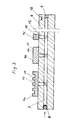
- a plurality of lower knives 4a, 4b, 4c etc. can be arranged next to one another on each shaft 6.
- at least one axial bore 7 is machined into the shaft 6.
- a ball valve 8 At one end of the bore 7 there is a ball valve 8, the other end is closed by a screw 9.
- Radial bores 10, 11 and 12 open into the bore 7, the radially outer ends of which represent exit points from which the compressed air blown in via the ball valve 8 can escape. These exit points are designated 13, 14 and 15.
- the exit points 13, 14 and 15 in FIG. 3 are arranged approximately in the middle of the respective lower knife, so that even if the respective associated lower knife should be displaced within certain limits in the axial direction of the shaft 6, the respective exit point of the respective lower knife is constantly covered. In other words, this means that the respective lower knife can only be displaced relative to the shaft 6 to such an extent that this lower knife just barely covers the respective outlet opening.
- the radial bores 10, 11 and 12 are incorporated in the shaft 6 such that they come to rest in the upper half 16 of this shaft when the shaft is at a standstill with a sectional representation of the shaft.
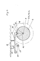
- a positioning device is provided which enables the shaft 6 to be stopped in an easily possible manner immediately before the respective positioning of the lower knives 4 in such a way that the bores 10, 11 and 12 come to lie in the upper half 16.
- the positioning device consists, for example, of a pawl 17 which can engage in a corresponding recess or groove 18 in the shaft 6.
- the pawl 17 can be snapped into the bore 18 with the aid of a compression spring 19.
- a switch 23 prevents the machine from starting in the event that the pawl 17 blocks the rotation of the shaft 6.
- the bore 18 is preferably made at one end of the shaft 6 so that most of the shaft 6 remains free to position the lower knife thereon.
- the knives or knife bushings can be shifted along the shaft 6 by both small and long distances, as long as only the respective knife covers the hole assigned to this knife. Due to the pressure medium emerging from the respective bore, in particular compressed air, the respective knife or the respective knife sleeve is raised by a small amount relative to the knife shaft and is able to slide on a thin cushion of pressure medium inserted between the shaft and knife. For this, it is not absolutely necessary to work special chambers into the inside of the knife, the knife sleeve or the knife holder for receiving the pressure medium. For example, it is also possible to use the knife, the lower knife sleeve or the knife holder to raise within the game that is already predetermined by the mechanical production of the machine parts involved.
- the respective upper knife work together with one edge during a certain cutting process and with another edge of the respective lower knife or the respective lower knife sleeve during another cutting process.
- This either increases the service life of the lower knife bushing or, with simultaneous displacement of the respective lower knife bushing relative to the upper knife, makes it easier to produce strips of different widths from materials to be cut from a web.
- the present invention aids in the changeover from one format to be cut and possibly wound up to another.
- any cutting dust that may accumulate between the knife shaft and knife holder can be blown out of the device by the pressure medium, especially when using compressed air.
- each separate lower knife can be moved a separate supply of pressure medium z. B. to assign compressed air so that only this one lower knife or its holder can be axially displaced relative to the shaft 6, while the other lower knives on the shaft 6 maintain their position.
Abstract
Um Schneidwerkzeuge zu verschieben, wird Druckmittel zwischen ihnen und der jeweiligen Welle eingelassen.In order to move cutting tools, pressure medium is let in between them and the respective shaft.
Description
Die vorliegende Erfindung betrifft eine Einrichtung zum Verändern der Position von Messern, insbesondere von Untermessern für umschlungenen Schnitt beim Längsschneiden von Papier, Folie, Gewebe oder ähnlichem bahnförmigem Material mit auf mindestens einer Welle aufgeschobenen, ringförmigen Untermessern oder Halterungen für diese Untermesser.The present invention relates to a device for changing the position of knives, in particular of lower knives for wrapped cutting when slitting paper, foil, tissue or similar web-like material with annular lower knives pushed onto at least one shaft or holders for these lower knives.
Beim Längsschneiden von Papier, Gewebe, Folie, Metallen oder dgl. unterscheidet man den sog. geraden Schnitt von dem sog. umschlungenen Schnitt. Bei dem geraden Schnitt läuft die in einzelne Streifen zu zerschneidende Bahn etwa tangential zwischen mindestens einem Ober-und mindestens einem Untermesser hindurch, so daß auf diese Weise aus einer Bahn mindestens zwei Streifen entstehen. Es können aber nicht nur ein Messerpaar, sondern auch mehrere Messerpaare miteinander zusammenarbeiten, um damit eine relativ breite Bahn in eine Vielzahl relativ schmaler Bahnen zu zerschneiden.When slitting paper, fabric, foil, metals or the like, a distinction is made between the so-called straight cut and the so-called looped cut. In the case of the straight cut, the web to be cut into individual strips runs approximately tangentially between at least one upper and at least one lower knife, so that at least two strips result from a web in this way. However, not only a pair of knives, but also several pairs of knives can work together to cut a relatively wide web into a plurality of relatively narrow webs.
Von Seiten des Endverarbeiters der zu schneidenden Bahn werden oftmals verschieden breite Bahnen gewünscht, weshalb die Forderung entsteht, eine relativ breite Bahn während eines Produktionsvorganges, beispielsweise in relativ breite und während eines anderen Produktionsvorganges in relativ schmale Bahnen zu zerschneiden. Diese zerschnittenen Bahnen werden in der Regel zu Rollen aufgewickelt, um damit beispielsweise auf leichte und bequeme Weise dem jeweiligen Endverarbeiter dieser Bahnen übersandt werden zu können.The end processor of the web to be cut often requests webs of different widths, which is why there is a need to cut a relatively wide web during one production process, for example into relatively wide webs and during another production process into relatively narrow webs. These cut webs are usually wound up into rolls, for example to be sent to the respective end processor of these railways in a simple and convenient manner.
Die jeweils wechselnden Wünsche des Endverarbeiters bedeuten für denjenigen, der eine relativ breite Bahn in Einzelbahnen zu unterteilen hat, daß die ihm zur Verfügung stehende Einrichtung entsprechend umgestellt werden muß. Dieser Vorgang wird üblicherweise mit "positionieren" bezeichnet.The changing requirements of the end processor mean for those who have to subdivide a relatively wide web into individual webs that the facility available to them must be changed accordingly. This process is usually referred to as "positioning".
Beim sog. geraden Schnitt ist es relativ einfach, Unter-und Obermesser zu positionieren, da die Bahn nicht gegen eines der beiden Messer drückt und seine Beweglichkeit behindert. Beim sog. umschlungenen Schnitt hingegen ist es sehr viel schwieriger, das von der Bahn umschlungene Messer zu verschieben, da die Bahn aufgrund der zum Zwecke des Verarbeitens in ihr notwendigerweise herrschenden Spannung gegen das Untermesser drückt. Das Untermesser wird dadurch in seiner Beweglichkeit eingeschränkt, weshalb es insbesondere in diesem Falle erforderlich ist, für eine leichtgängige Verschiebung des Untermessers dann Sorge zu tragen, wenn die Position dieses Untermessers verändert werden soll.In the case of the so-called straight cut, it is relatively easy to position the lower and upper knives, since the web does not press against one of the two knives and impairs its mobility. In the case of the so-called looped cut, on the other hand, it is much more difficult to move the knife wrapped in the web, since the web presses against the lower knife due to the tension that is necessarily present in it for processing. The lower knife is thereby limited in its mobility, which is why it is particularly necessary in this case to ensure a smooth displacement of the lower knife when the position of this lower knife is to be changed.
Aus der DE-AS 18 02 305 ist eine Einrichtung vorbekannt, bei der Druckluft zwischen die zueinander verschiebbaren Teile der Schlittenführung eines Messers eingedrückt wird. Diese vorbekannte Einrichtung setzt aber einen schweren, aufwendigen Schlitten voraus, der zudem einen noch aufwendigeren Einzelantrieb für jedes Untermesser bedingt.From DE-AS 18 02 305 a device is known in which compressed air is pressed between the mutually displaceable parts of the slide guide of a knife. However, this known device requires a heavy, complex slide, which also requires an even more complex individual drive for each undercutter.
Die Einrichtung nach der EP-A 96 026 (WO 83/02083) verfolgt das Ziel, eine Nabe mit aufzuweiten. Dieses Ziel wird jedoch von der vorgeschlagenen Erfindung nicht angestrebt. Eine Aufweitung von Messernaben steht bei der vorgeschlagenen Erfindung nicht zur Diskussion. Dies .gilt ebenfalls im Hinblick auf die französische Patentanmeldung 23 40 170.The device according to EP-A 96 026 (WO 83/02083) ver follows the goal of widening a hub. However, this aim is not aimed at by the proposed invention. A widening of knife hubs is not up for discussion in the proposed invention. This also applies to
Von der geschilderten Problematik ausgehend, besteht die Aufgabe, eine möglichst einfache und leichtgängige Einrichtung zum Verschieben der Messer oder ihrer Halterungen, insbesondere derjenigen Messer oder Halterungen für das sog. Untermesser vorzuschlagen, insbesondere für den Fall, daß das Untermes-ser zumindest teilweise von der zu zerschneidenden Bahn umschlungen wird.Based on the problem described, the task is to propose a simple and smooth-running device for moving the knives or their holders, in particular those knives or holders for the so-called lower knife, in particular in the event that the lower knife is at least partially from the is wrapped into a cutting web.
Diese Aufgabe wird dadurch gelöst, daß pro Halterung eines Untermessers oder pro Untermesser in die die Untermesser oder Halterungen unterstützende Welle mindestens eine radiale Bohrung eingearbeitet ist, die Austrittsstellen dieser radialen Bohrung oder dieser radialen Bohrungen innerhalb desjenigen axialen Bereiches der Welle angeordnet sind, der auch bei in Längsrichtung der Welle geringfügiger Verschiebung der Halterung oder des Untermessers von dieser Halterung oder dem Untermesser ständig bedeckt ist, die Austrittsstellen der Bohrungen bei Stillstand der Welle in der oberen Hälfte der Welle positioniert sind, eine diese Positionierung ermöglichende mit der Welle in Eingriff bringbare Positioniereinrichtung und eine Zuleitung zum Einleiten von Druckmittel in die radialen Bohrungen vorgesehen sind.This object is achieved in that at least one radial bore is incorporated into each support of an undercutter or per undercutter in the shaft supporting the undercutter or supports, the exit points of this radial bore or these radial bores are arranged within the axial region of the shaft, which also at in the longitudinal direction of the shaft slight displacement of the holder or the lower knife is constantly covered by this holder or the lower knife, the exit points of the bores are positioned in the upper half of the shaft when the shaft is at a standstill, a positioning device which enables this positioning and can be brought into engagement a feed line for introducing pressure medium into the radial bores is provided.
Durch die vorliegende Erfindung wird es ermöglicht, das Untermesser in radialer Richtung gegenüber der es unterstützenden Welle innerhalb des durch die Herstellung bedingten Spieles so weit zu verschieben, daß es auf leichtgängige Weise in axialer Richtung der Welle verschoben werden kann. Damit wird es ermöglicht, auch relativ schwere Untermesser, insbesondere sog. Schneidbüchsen, leichtgängig von einer Position in eine andere zu verschieben. Dadurch wiederum wird es ermöglicht, die gesamte in Rede stehende Einrichtung auf einfache und schnelle Weise von einer Produktionsart auf eine andere umzustellen, d. h. beispielsweise von einer Breite von zu schneidenden Streifen auf eine andere.The present invention makes it possible to make the lower knife in the radial direction with respect to it supporting shaft within the game due to the manufacturing so far that it can be easily moved in the axial direction of the shaft. This makes it possible to move relatively heavy lower knives, in particular so-called cutting sleeves, from one position to another with ease. This in turn makes it possible to switch the entire device in question from one type of production to another in a simple and quick manner, ie for example from a width of strips to be cut to another.
Anhand eines in den beigefügten Figuren schematisch abgebildeten, den Grundgedanken nicht begrenzenden Ausführungsbeispiels wird die vorgeschlagene Einrichtung näher erläutert. In den Figuren sind im vorliegenden Zusammenhang nicht wesentliche Maschinenteile einer übersichtlicheren Darstellungsweise wegen nicht zeichnerisch dargestellt, vielmehr sind in den Figuren nur diejenigen Teile gezeigt, die zur näheren Erläuterung des Grundgedankens erforderlich sind.The proposed device is explained in more detail with reference to an exemplary embodiment schematically depicted in the attached figures, which does not limit the basic idea. In the present context, the essential parts of the machine are not shown in the drawing because of a clearer way of illustration, but rather only those parts are shown in the figures which are necessary for a more detailed explanation of the basic idea.
Die einzelnen Figuren bedeuten:
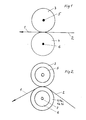
- Figur 1): Prinzipskizze des sog. geraden Schnittes
- Figur 2): Prinzipskizze des sog. umschlungenen Schnittes
- Figur 3): teilweiser Schnitt durch eine Untermesser unterstützende Welle
- Figur 4): Positioniereinrichtung für die das Untermes- ser unterstützende Welle
- Figur 5): Draufsicht auf die Einrichtung nach
Figur 4
- Figure 1): Sketch of the so-called straight cut
- Figure 2): Sketch of the so-called looped cut
- Figure 3): partial section through a lower knife supporting shaft
- Figure 4): Positioning device for the shaft supporting the lower knife
- Figure 5): Top view of the device according to Figure 4
Bei der Einrichtung nach Figur 1 läuft eine in mehrere Streifen 1 zu zerschneidende Bahn 2 durch ein Messerpaar hindurch. Jedes Messerpaar umfaßt ein Obermesser 3 und mindestens ein Untermesser 4. Das oder die Obermesser 3 ist/sind auf der Welle 5 befestigt, während das oder die Untermesser 4 auf einer Welle 6 befestigt sind. Jede der Wellen 5 oder 6 ist drehbar in einem entsprechend ausgebildeten Maschinengestell gelagert und kann darüber hinaus angetrieben sein. Zum Zwecke der Veränderung ihrer Position, d. h. der Breite von zu schneidenden Streifen 1 können die Obermesser 3 entlang der Welle 5-also in Blickrichtung der Figur 1-und die Untermesser 4 entlang der Welle 6 je nach Bedarf verschoben werden. Diese Verschiebung kann relativ geringfügig sein, insbesondere dann, wenn mehrere schneidende Stellen pro Untermesser vorgesehen sind. Beispielsweise können Untermesser in Form sog. Schneidbüchsen ausgeführt sein, wobei jede Schneidbüchse eine Vielzahl von schneidenden Kanten enthält. Mit jeder dieser Kanten kann ein und dasselbe Obermesser wahlweise zusammenarbeiten, so daß es oftmals bei sog. Formatumstellungen notwendig ist, das Obermesser um eine relativ weite axiale Erstreckung zu verschieben, das Untermesser hingegen nur um eine sehr viel kürzere, um auf diese Weise zu ermöglichen, daß das Obermesser mit einer anderen schneidenden Kante, einer sog. Schneidnut als vorher zusammenarbeiten kann.In the device according to FIG. 1, a
Aus Figur 2 ist ersichtlich, daß die Bahn 2 und die daraus geschnittenen Streifen 1 das oder die Untermes- ser 4 teilweise umschlingen. Auf diese Weise wird die zu zerschneidende Bahn während des Schneidvorganges besser gehalten als im Falle des sog. geraden Schnittes nach Figur 1. Wenn die Untermesser 4 im Falle des sog. umschlungenen Schnittes nach Figur 2 in axialer Richtung der Welle 6 verschoben werden müssen, dann drücken die zu zerschneidende Bahn 2 und die daraus geschnittenen Streifen 1 aufgrund der in ihr wohnenden mechanischen Spannung das oder die Untermesser 4, deren Gewicht insbesondere dann, wenn es sich um sog. Schneidbüchsen handelt, nicht zu vernachlässigen ist, gegen die das oder die Untermesser unterstützende Welle 6 und behindern damit ein Verschieben der Untermesser 4 in axialer Richtung der Welle 6, also in Blickrichtung der Figur 2.It can be seen from FIG. 2 that the
Aus Figur 3 geht hervor, daß auf jeder Welle 6 mehrere Untermesser 4a, 4b, 4c usw. nebeneinander angeordnet werden können. Außerdem ist in die Welle 6 mindestens eine axiale Bohrung 7 eingearbeitet. An dem einen Ende der Bohrung 7 befindet sich ein Kugelventil 8, das andere Ende ist durch eine Schraube 9 verschlossen. In die Bohrung 7 münden radiale Bohrungen 10, 11 und 12, deren radial äußere Enden Austrittsstellen darstellen, aus denen die über das Kugelventil 8 eingeblasene Druckluft austreten kann. Diese Austrittsstellen sind mit 13, 14 und 15 bezeichnet. Die Austrittsstellen 13, 14 und 15 sind in Figur 3 etwa in der Mitte des jeweiligen Untermessers angeordnet, so daß auch dann, wenn das jeweils zugehörige Untermesser in axialer Richtung der Welle 6 innerhalb gewisser Grenzen verschoben werden sollte, die jeweilige Austrittsstelle von dem jeweiligen Untermesser ständig bedeckt wird. Das bedeutet mit anderen Worten, daß das jeweilige Untermesser gegenüber der Welle 6 nur soweit verschoben werden kann, als daß dieses Untermesser die jeweilige Austrittsöffnung gerade noch bedeckt.It can be seen from FIG. 3 that a plurality of
Die radialen Bohrungen 10, 11 und 12 sind derart in die Welle 6 eingearbeitet, daß sie bei Stillstand der Welle bei schnittbildlicher Darstellung der Welle in die obere Hälfte 16 dieser Welle zu liegen kommen. Um dies zu erleichtern, ist eine Positioniereinrichtung vorgesehen, die es ermöglicht, die Welle 6 unmittelbar vor dem jeweiligen Positionieren der Untermesser 4 auf leicht mögliche Weise derart anzuhalten, daß die Bohrungen 10, 11 und 12 in die obere Hälfte 16 zu liegen kommen.The
Die Positioniereinrichtung besteht beispielsweise aus einer Klinke 17, welche-in eine entsprechende Vertiefung oder Nut 18 der Welle 6 eingreifen kann. Beispielsweise kann die Klinke 17 mit Hilfe einer Druckfeder 19 in die Bohrung 18 eingerastet werden. Mit Hilfe eines Nockens 20 wird es ermöglicht, die Klinke 17 aus der Bohrung oder Vertiefung 18 auszurasten. Dabei ist es möglich, den Nocken 20 auf einer Welle 21 zusammen mit dieser drehbar zu lagern und die Welle 21 mit Hilfe eines Handhebels 22 zu verdrehen. Ein Schalter 23 verhindert das Anlaufen der Maschine für denjenigen Fall, in welchem die Klinke 17 die Drehung der Welle 6 sperrt.The positioning device consists, for example, of a
Die Bohrung 18 ist vorzugsweise an einem Ende der Welle 6 angebracht, so daß der größte Teil der Welle 6 frei bleibt, um darauf Untermesser zu positionieren.The
Neben dieser mechanischen Möglichkeit der Positionierung der Welle 6 ist es denkbar, diese Welle mit einem sog. Drehwinkelgeber auszustatten und auf diese Weise die Welle 6 auf elektrische oder elektronische Weise zusammen mit einer auf die Welle 6 wirkenden ein- und ausschaltbaren Bremse derart anzuhalten, daß die Austrittsstellen 13, 14 und 15 der Bohrungen 10, 11 und 12 im wesentlichen nach oben weisen, also in der oberen Hälfte der Welle 6 angeordnet werden. Auf diese Weise ist es möglich, durch Einleiten eines Druckmittels, wie beispielsweise Druckluft, die Untermesser um geringfügige Beträge gegenüber der Welle 6 nach oben zu heben und ein Polster von Druckmittel, beispielsweise von Druckluft zu erhalten, auf dem das jeweilige Untermesser schwimmend verschoben werden kann.In addition to this mechanical possibility of positioning the
Auf diese Weise ist es möglich, auch schwere Schneidbüchsen, welche bereits aufgrund ihres eigenen Gewichtes durch eine Bedienungsperson gegenüber der Welle 6 (Messerwelle) von Hand nicht mehr verschoben werden können, leichtgängig zu verschieben.In this way it is possible to move even heavy cutting sleeves, which due to their own weight cannot be moved by an operator relative to the shaft 6 (knife shaft) by hand.
Die Messer oder Messerbüchsen können dabei sowohl um geringfügige als auch um größere Strecken entlang der Welle 6 verschoben werden, solange nur das jeweilige Messer die jeweils diesem Messer zugeordnete Bohrung bedeckt. Durch das aus der jeweiligen Bohrung austretende Druckmittel, insbesondere Druckluft, wird das jeweilige Messer oder die jeweilige Messerbüchse um geringfügige Beträge gegenüber der Messerwelle gehoben und vermag auf einem dünnen Polster von zwischen Welle und Messer eingeschobenem Druckmittel zu gleiten. Dafür ist es nicht unbedingt erforderlich, in das Innere des Messers, der Messerbüchse oder des Messerhalters besondere Kammern für die Aufnahme des Druckmittels einzuarbeiten. Beispielsweise ist es auch möglich, das Messer, die Untermesserbüchse oder den Messerhalter innerhalb desjenigen Spieles anzuheben, das durch die mechanische Herstellung der beteiligten Maschinenteile bereits vorgegeben ist.The knives or knife bushings can be shifted along the
Es ist ebenfalls möglich, das jeweilige Obermesser bei einem bestimmten Schneidvorgang mit der einen und bei einem anderen Schneidvorgang mit einer anderen Kante des jeweiligen Untermessers oder der jeweiligen Untermesserbüchse zusammenarbeiten zu lassen. Dies erhöht entweder die Standzeit der Untermesserbüchse oder erleichtert bei gleichzeitiger Verschiebung der jeweiligen Untermesserbüchse gegenüber dem Obermesser die Herstellung verschieden breiter Streifen von aus einer Bahn auszuschneidenden Materialien. Auf diese Weise hilft die vorliegende Erfindung bei der Umstellung von einem zu schneidenden und evtl. aufzuwickelnden Format auf ein anderes.It is also possible to have the respective upper knife work together with one edge during a certain cutting process and with another edge of the respective lower knife or the respective lower knife sleeve during another cutting process. This either increases the service life of the lower knife bushing or, with simultaneous displacement of the respective lower knife bushing relative to the upper knife, makes it easier to produce strips of different widths from materials to be cut from a web. In this way, the present invention aids in the changeover from one format to be cut and possibly wound up to another.
Daneben kann evtl. sich zwischen Messerwelle und Messerhalterung ansammelnder Schneidstaub durch das Druckmittel, insbesondere bei der Verwendung von Druckluft aus der Einrichtung herausgeblasen werden.In addition, any cutting dust that may accumulate between the knife shaft and knife holder can be blown out of the device by the pressure medium, especially when using compressed air.
Es ist von geringem Belang, ob die jeweiligen Untermes- ser oder ihre mit der Welle 6 in Berührung stehenden Halterungen relativ breit oder relativ schmal sind, wie beispielsweise die Untermesser 4a oder 4c. Es ist auch möglich, jedem zu verschiebenden Untermesser jeweils eine separate Zuleitung von Druckmittel z. B. Druckluft zuzuordnen, so daß nur dieses eine Untermes- ser oder seine Halterung gegenüber der Welle 6 axial verschoben werden kann, während die anderen auf der Welle 6 befindlichen Untermesser ihre Position beibehalten.It is of little importance whether the respective lower knives or their holders in contact with the
- 1 Streifen1 strip
- 2 Bahn2 lanes
- 3 Obermesser3 upper knives
- 4 Untermesser(4a, 4b, 4c usw.)4 lower knives (4a, 4b, 4c etc.)
- 5 Welle5 wave
- 6 Welle6 wave
- 7 axiale Bohrung7 axial bore
- 8 Kugelventil8 ball valve
- 9 Schraube9 screw
- 10 radiale Bohrung10 radial bore
- 11 radiale Bohrung11 radial bore
- 12 radiale Bohrung12 radial bore
- 13 Austrittsstelle13 exit point
- 14 Austrittsstelle14 exit point
- 15 Austrittsstelle15 exit point
-
16 obere Hälfte der Welle 616 upper half of the
shaft 6 - 17 Klinke17 jack
- 18 Bohrung oder Vertiefung18 hole or recess
- 19 Druckfeder19 compression spring
- 20 Nocken20 cams
- 21 Welle21 wave
- 22 Handhebel22 hand lever
- 23 Schalter23 switches
Claims (1)
Applications Claiming Priority (2)
| Application Number | Priority Date | Filing Date | Title |
|---|---|---|---|
| DE3533739 | 1985-09-21 | ||
| DE19853533739 DE3533739A1 (en) | 1985-09-21 | 1985-09-21 | SLIDING DEVICE |
Publications (2)
| Publication Number | Publication Date |
|---|---|
| EP0219890A1 true EP0219890A1 (en) | 1987-04-29 |
| EP0219890B1 EP0219890B1 (en) | 1989-04-05 |
Family
ID=6281597
Family Applications (1)
| Application Number | Title | Priority Date | Filing Date |
|---|---|---|---|
| EP86201433A Expired EP0219890B1 (en) | 1985-09-21 | 1986-08-18 | Shift device |
Country Status (6)
| Country | Link |
|---|---|
| US (1) | US4759249A (en) |
| EP (1) | EP0219890B1 (en) |
| JP (1) | JPS62130195A (en) |
| DE (2) | DE3533739A1 (en) |
| ES (1) | ES2003102A6 (en) |
| FI (1) | FI83049C (en) |
Families Citing this family (15)
| Publication number | Priority date | Publication date | Assignee | Title |
|---|---|---|---|---|
| DE4002917A1 (en) * | 1990-02-01 | 1991-08-08 | Goebel Gmbh Maschf | DEVICE FOR HOLDING A CUTTING TOOL |
| US5386950A (en) * | 1992-06-08 | 1995-02-07 | Abt; Richard | Apparatus and method for preparing individual wound rolls from a slitted web of material |
| US5562008A (en) * | 1995-03-20 | 1996-10-08 | Danieli Wean | Edge trimmer starter punch |
| GB2299046A (en) * | 1995-03-21 | 1996-09-25 | Nestle Sa | Ultrasonic cutting device |
| US6012372A (en) * | 1996-01-18 | 2000-01-11 | Laster; James E. | Adjustable arbor and cutting elements |
| US5861185A (en) | 1996-08-22 | 1999-01-19 | Mars, Incorporated | Ultrasonic forming of confectionery products |
| US5871783A (en) | 1996-08-22 | 1999-02-16 | Mars, Incorporated | Apparatus for ultrasonically forming confectionery products |
| US5871793A (en) | 1996-11-27 | 1999-02-16 | Mars Incorporated | Puffed cereal cakes |
| US5846584A (en) | 1997-04-30 | 1998-12-08 | Mars, Incorporated | Apparatus and method for forming cereal food products |
| US20020127310A1 (en) * | 1998-12-07 | 2002-09-12 | Capodieci Roberto A. | Cereal food product and method |
| US6368647B1 (en) * | 1998-12-29 | 2002-04-09 | Mars, Incorporated | Ultrasonically activated continuous slitter apparatus and method |
| US6574944B2 (en) * | 2001-06-19 | 2003-06-10 | Mars Incorporated | Method and system for ultrasonic sealing of food product packaging |
| US6655948B2 (en) | 2001-08-31 | 2003-12-02 | Mars, Incorporated | System of ultrasonic processing of pre-baked food product |
| US6635292B2 (en) * | 2001-10-26 | 2003-10-21 | Mars, Incorporated | Ultrasonic rotary forming of food products |
| US10639728B2 (en) * | 2016-04-19 | 2020-05-05 | Jdc, Inc. | Disposing device of shaft-body insertion objects |
Citations (6)
| Publication number | Priority date | Publication date | Assignee | Title |
|---|---|---|---|---|
| DE1038902B (en) * | 1954-02-02 | 1958-09-11 | Jagenberg Werke Ag | Longitudinal cutting device on roll cutting machines |
| DE1802305B1 (en) * | 1967-10-11 | 1970-07-16 | Masson Scott Thrissell Eng Ltd | Adjustment device for length cutter |
| DE2126407B2 (en) * | 1971-05-27 | 1972-11-16 | Ungerer Geb. Dollinger, Irma, 7530 Pforzheim | CLAMPING SHAFT FOR ROTATING TOOLS AND GUIDES |
| FR2340170A1 (en) * | 1976-02-06 | 1977-09-02 | Metal Box Co Ltd | POSITIONING A HUB, ESPECIALLY TOOL HOLDER, ON A SHAFT |
| DE2756997A1 (en) * | 1976-12-30 | 1978-07-06 | Masson Scott Thrissell Eng Ltd | PNEUMATIC CUTTER ROLLER |
| WO1983002083A1 (en) * | 1981-12-17 | 1983-06-23 | Spoerndli, Max | Cutting device |
Family Cites Families (2)
| Publication number | Priority date | Publication date | Assignee | Title |
|---|---|---|---|---|
| US3753517A (en) * | 1971-11-26 | 1973-08-21 | Teijin Ltd | Guide roll for filaments |
| SE417056B (en) * | 1979-07-19 | 1981-02-23 | Alani Safwat David | APPLICATION DEVICE FOR TREATMENT OR TREATMENT |
-
1985
- 1985-09-21 DE DE19853533739 patent/DE3533739A1/en not_active Withdrawn
-
1986
- 1986-08-18 EP EP86201433A patent/EP0219890B1/en not_active Expired
- 1986-08-18 DE DE8686201433T patent/DE3662658D1/en not_active Expired
- 1986-09-19 FI FI863806A patent/FI83049C/en not_active IP Right Cessation
- 1986-09-19 ES ES8602019A patent/ES2003102A6/en not_active Expired
- 1986-09-22 JP JP61222269A patent/JPS62130195A/en active Granted
- 1986-09-22 US US06/909,912 patent/US4759249A/en not_active Expired - Fee Related
Patent Citations (6)
| Publication number | Priority date | Publication date | Assignee | Title |
|---|---|---|---|---|
| DE1038902B (en) * | 1954-02-02 | 1958-09-11 | Jagenberg Werke Ag | Longitudinal cutting device on roll cutting machines |
| DE1802305B1 (en) * | 1967-10-11 | 1970-07-16 | Masson Scott Thrissell Eng Ltd | Adjustment device for length cutter |
| DE2126407B2 (en) * | 1971-05-27 | 1972-11-16 | Ungerer Geb. Dollinger, Irma, 7530 Pforzheim | CLAMPING SHAFT FOR ROTATING TOOLS AND GUIDES |
| FR2340170A1 (en) * | 1976-02-06 | 1977-09-02 | Metal Box Co Ltd | POSITIONING A HUB, ESPECIALLY TOOL HOLDER, ON A SHAFT |
| DE2756997A1 (en) * | 1976-12-30 | 1978-07-06 | Masson Scott Thrissell Eng Ltd | PNEUMATIC CUTTER ROLLER |
| WO1983002083A1 (en) * | 1981-12-17 | 1983-06-23 | Spoerndli, Max | Cutting device |
Also Published As
| Publication number | Publication date |
|---|---|
| JPS62130195A (en) | 1987-06-12 |
| FI83049C (en) | 1991-05-27 |
| EP0219890B1 (en) | 1989-04-05 |
| JPH0215354B2 (en) | 1990-04-11 |
| DE3533739A1 (en) | 1987-03-26 |
| FI83049B (en) | 1991-02-15 |
| FI863806A (en) | 1987-03-22 |
| ES2003102A6 (en) | 1988-10-16 |
| US4759249A (en) | 1988-07-26 |
| FI863806A0 (en) | 1986-09-19 |
| DE3662658D1 (en) | 1989-05-11 |
Similar Documents
| Publication | Publication Date | Title |
|---|---|---|
| EP0219890B1 (en) | Shift device | |
| DE3031040C2 (en) | ||
| DE3714662C2 (en) | ||
| DE2436717A1 (en) | SLOT AND FOLDING DEVICE FOR CONTINUOUS MATERIAL TRAILS | |
| DE2701068A1 (en) | SLOTING DEVICE FOR RAIL-SHAPED MATERIAL | |
| DE2600718B2 (en) | Device for dividing flat material webs into longitudinal strips of the desired width | |
| EP1065031A2 (en) | Apparatus for transversely perforating a web | |
| DE10356037A1 (en) | Corrugated cardboard web cutting device that can be used to make incomplete transverse cuts has knife and counter rollers that are controlled by a control unit so that a counter body and knife are displaced relative to each other | |
| DE10047545B4 (en) | Cutting and transporting roller with integrated cutting device with pivotable cutting surfaces and method for cutting material webs by means of such a roller | |
| EP1415944A1 (en) | Apparatus for the adjustment of pressing rollers and/or cutting blades in folding machines | |
| DE3634198A1 (en) | CUTTER | |
| DE3234904A1 (en) | TAPE ADHESIVE | |
| EP0791549A2 (en) | Method and device for winding a longitudinally cut web of material | |
| DE2350580A1 (en) | CHANGING DEVICE FOR LAYERS ON PACKING MACHINES | |
| DE3103958C2 (en) | Device for splitting off a strip of material from a moving material web | |
| DE2805211C3 (en) | Device for longitudinal cutting of material webs | |
| DE3901854A1 (en) | DEVICE FOR JOINING MATERIAL RAILS | |
| DE60009421T2 (en) | Tape laying unit for applying a band of composite material | |
| DE8527026U1 (en) | Moving device | |
| DE60109975T2 (en) | Cutting machine for a variety of kitchen and / or toilet paper rolls | |
| DE2828427C2 (en) | Device for the positive delivery of thread to circular knitting machines | |
| DE60011271T2 (en) | METHOD AND DEVICE IN THE PROCESS OF WINDING UP A PAPER | |
| DE2706510C2 (en) | Iron cutters | |
| DE4425201C2 (en) | Method and device for separating a plastic material web in a roll cutting and winding machine | |
| DE2414564C3 (en) | Device for the transverse cutting of continuously running material webs perforated at intervals to form AbreiBschwächungsUnien transversely |
Legal Events
| Date | Code | Title | Description |
|---|---|---|---|
| PUAI | Public reference made under article 153(3) epc to a published international application that has entered the european phase |
Free format text: ORIGINAL CODE: 0009012 |
|
| AK | Designated contracting states |
Kind code of ref document: A1 Designated state(s): BE CH DE FR GB IT LI NL SE |
|
| ITCL | It: translation for ep claims filed |
Representative=s name: BARZANO' E ZANARDO MILANO S.P.A. |
|
| 17P | Request for examination filed |
Effective date: 19870313 |
|
| EL | Fr: translation of claims filed | ||
| TCNL | Nl: translation of patent claims filed | ||
| 17Q | First examination report despatched |
Effective date: 19880511 |
|
| ITF | It: translation for a ep patent filed |
Owner name: BARZANO' E ZANARDO MILANO S.P.A. |
|
| GRAA | (expected) grant |
Free format text: ORIGINAL CODE: 0009210 |
|
| AK | Designated contracting states |
Kind code of ref document: B1 Designated state(s): BE CH DE FR GB IT LI NL SE |
|
| GBT | Gb: translation of ep patent filed (gb section 77(6)(a)/1977) | ||
| REF | Corresponds to: |
Ref document number: 3662658 Country of ref document: DE Date of ref document: 19890511 |
|
| ET | Fr: translation filed | ||
| PLBE | No opposition filed within time limit |
Free format text: ORIGINAL CODE: 0009261 |
|
| STAA | Information on the status of an ep patent application or granted ep patent |
Free format text: STATUS: NO OPPOSITION FILED WITHIN TIME LIMIT |
|
| 26N | No opposition filed | ||
| ITTA | It: last paid annual fee | ||
| EAL | Se: european patent in force in sweden |
Ref document number: 86201433.9 |
|
| PGFP | Annual fee paid to national office [announced via postgrant information from national office to epo] |
Ref country code: NL Payment date: 19970831 Year of fee payment: 12 |
|
| PGFP | Annual fee paid to national office [announced via postgrant information from national office to epo] |
Ref country code: CH Payment date: 19971118 Year of fee payment: 12 |
|
| PGFP | Annual fee paid to national office [announced via postgrant information from national office to epo] |
Ref country code: FR Payment date: 19980731 Year of fee payment: 13 |
|
| PGFP | Annual fee paid to national office [announced via postgrant information from national office to epo] |
Ref country code: SE Payment date: 19980817 Year of fee payment: 13 |
|
| PGFP | Annual fee paid to national office [announced via postgrant information from national office to epo] |
Ref country code: BE Payment date: 19980819 Year of fee payment: 13 |
|
| PG25 | Lapsed in a contracting state [announced via postgrant information from national office to epo] |
Ref country code: LI Free format text: LAPSE BECAUSE OF NON-PAYMENT OF DUE FEES Effective date: 19980831 Ref country code: CH Free format text: LAPSE BECAUSE OF NON-PAYMENT OF DUE FEES Effective date: 19980831 |
|
| PG25 | Lapsed in a contracting state [announced via postgrant information from national office to epo] |
Ref country code: NL Free format text: LAPSE BECAUSE OF NON-PAYMENT OF DUE FEES Effective date: 19990301 |
|
| REG | Reference to a national code |
Ref country code: CH Ref legal event code: PL |
|
| NLV4 | Nl: lapsed or anulled due to non-payment of the annual fee |
Effective date: 19990301 |
|
| PGFP | Annual fee paid to national office [announced via postgrant information from national office to epo] |
Ref country code: DE Payment date: 19990817 Year of fee payment: 14 |
|
| PGFP | Annual fee paid to national office [announced via postgrant information from national office to epo] |
Ref country code: GB Payment date: 19990818 Year of fee payment: 14 |
|
| PG25 | Lapsed in a contracting state [announced via postgrant information from national office to epo] |
Ref country code: SE Free format text: THE PATENT HAS BEEN ANNULLED BY A DECISION OF A NATIONAL AUTHORITY Effective date: 19990830 |
|
| PG25 | Lapsed in a contracting state [announced via postgrant information from national office to epo] |
Ref country code: BE Free format text: LAPSE BECAUSE OF NON-PAYMENT OF DUE FEES Effective date: 19990831 |
|
| BERE | Be: lapsed |
Owner name: MASCHINENFABRIK GOEBEL G.M.B.H. Effective date: 19990831 |
|
| PG25 | Lapsed in a contracting state [announced via postgrant information from national office to epo] |
Ref country code: FR Free format text: LAPSE BECAUSE OF NON-PAYMENT OF DUE FEES Effective date: 20000428 |
|
| EUG | Se: european patent has lapsed |
Ref document number: 86201433.9 |
|
| PG25 | Lapsed in a contracting state [announced via postgrant information from national office to epo] |
Ref country code: DE Free format text: LAPSE BECAUSE OF THE APPLICANT RENOUNCES Effective date: 20000629 |
|
| REG | Reference to a national code |
Ref country code: FR Ref legal event code: ST |
|
| PG25 | Lapsed in a contracting state [announced via postgrant information from national office to epo] |
Ref country code: GB Free format text: LAPSE BECAUSE OF NON-PAYMENT OF DUE FEES Effective date: 20000818 |
|
| GBPC | Gb: european patent ceased through non-payment of renewal fee |
Effective date: 20000818 |
|
| PG25 | Lapsed in a contracting state [announced via postgrant information from national office to epo] |
Ref country code: IT Free format text: LAPSE BECAUSE OF NON-PAYMENT OF DUE FEES;WARNING: LAPSES OF ITALIAN PATENTS WITH EFFECTIVE DATE BEFORE 2007 MAY HAVE OCCURRED AT ANY TIME BEFORE 2007. THE CORRECT EFFECTIVE DATE MAY BE DIFFERENT FROM THE ONE RECORDED. Effective date: 20050818 |