EP0219367B1 - Organische Elektrolysezelle mit Verbrauchselektrode - Google Patents
Organische Elektrolysezelle mit Verbrauchselektrode Download PDFInfo
- Publication number
- EP0219367B1 EP0219367B1 EP86401895A EP86401895A EP0219367B1 EP 0219367 B1 EP0219367 B1 EP 0219367B1 EP 86401895 A EP86401895 A EP 86401895A EP 86401895 A EP86401895 A EP 86401895A EP 0219367 B1 EP0219367 B1 EP 0219367B1
- Authority
- EP
- European Patent Office
- Prior art keywords
- electrode
- electrolysis cell
- organic
- electrosynthesis
- group
- Prior art date
- Legal status (The legal status is an assumption and is not a legal conclusion. Google has not performed a legal analysis and makes no representation as to the accuracy of the status listed.)
- Expired - Lifetime
Links
- 238000005868 electrolysis reaction Methods 0.000 title claims description 53
- 229910052751 metal Inorganic materials 0.000 claims abstract description 32
- 239000002184 metal Substances 0.000 claims abstract description 32
- 239000011810 insulating material Substances 0.000 claims abstract description 9
- 239000007787 solid Substances 0.000 claims abstract description 9
- 150000002894 organic compounds Chemical class 0.000 claims abstract description 7
- 238000003487 electrochemical reaction Methods 0.000 claims abstract description 5
- 150000002902 organometallic compounds Chemical class 0.000 claims abstract description 5
- 239000008151 electrolyte solution Substances 0.000 claims abstract 2
- 150000004820 halides Chemical class 0.000 claims description 17
- 229910052782 aluminium Inorganic materials 0.000 claims description 15
- XAGFODPZIPBFFR-UHFFFAOYSA-N aluminium Chemical compound [Al] XAGFODPZIPBFFR-UHFFFAOYSA-N 0.000 claims description 15
- FYYHWMGAXLPEAU-UHFFFAOYSA-N Magnesium Chemical compound [Mg] FYYHWMGAXLPEAU-UHFFFAOYSA-N 0.000 claims description 14
- 239000011777 magnesium Substances 0.000 claims description 14
- 229910052749 magnesium Inorganic materials 0.000 claims description 14
- 229910045601 alloy Inorganic materials 0.000 claims description 13
- 239000000956 alloy Substances 0.000 claims description 13
- HCHKCACWOHOZIP-UHFFFAOYSA-N Zinc Chemical compound [Zn] HCHKCACWOHOZIP-UHFFFAOYSA-N 0.000 claims description 11
- 229910052725 zinc Inorganic materials 0.000 claims description 11
- 239000011701 zinc Substances 0.000 claims description 11
- 150000001735 carboxylic acids Chemical class 0.000 claims description 10
- 150000002576 ketones Chemical class 0.000 claims description 10
- 239000000463 material Substances 0.000 claims description 9
- OKTJSMMVPCPJKN-UHFFFAOYSA-N Carbon Chemical compound [C] OKTJSMMVPCPJKN-UHFFFAOYSA-N 0.000 claims description 8
- PXHVJJICTQNCMI-UHFFFAOYSA-N Nickel Chemical compound [Ni] PXHVJJICTQNCMI-UHFFFAOYSA-N 0.000 claims description 8
- 150000001299 aldehydes Chemical class 0.000 claims description 8
- 239000004033 plastic Substances 0.000 claims description 8
- 229920003023 plastic Polymers 0.000 claims description 8
- CURLTUGMZLYLDI-UHFFFAOYSA-N Carbon dioxide Chemical compound O=C=O CURLTUGMZLYLDI-UHFFFAOYSA-N 0.000 claims description 7
- 150000001298 alcohols Chemical class 0.000 claims description 6
- 229910052799 carbon Inorganic materials 0.000 claims description 6
- 125000002915 carbonyl group Chemical group [*:2]C([*:1])=O 0.000 claims description 6
- 239000003960 organic solvent Substances 0.000 claims description 6
- 239000010935 stainless steel Substances 0.000 claims description 5
- 229910001220 stainless steel Inorganic materials 0.000 claims description 5
- 125000000524 functional group Chemical group 0.000 claims description 4
- 229910052759 nickel Inorganic materials 0.000 claims description 4
- 150000007524 organic acids Chemical class 0.000 claims description 4
- 229910002092 carbon dioxide Inorganic materials 0.000 claims description 3
- 239000001569 carbon dioxide Substances 0.000 claims description 3
- 239000004020 conductor Substances 0.000 claims description 2
- 239000004411 aluminium Substances 0.000 claims 3
- 230000005611 electricity Effects 0.000 claims 2
- 239000013543 active substance Substances 0.000 abstract 1
- ZMXDDKWLCZADIW-UHFFFAOYSA-N N,N-Dimethylformamide Chemical compound CN(C)C=O ZMXDDKWLCZADIW-UHFFFAOYSA-N 0.000 description 15
- YTPLMLYBLZKORZ-UHFFFAOYSA-N Thiophene Chemical compound C=1C=CSC=1 YTPLMLYBLZKORZ-UHFFFAOYSA-N 0.000 description 14
- JUJWROOIHBZHMG-UHFFFAOYSA-N Pyridine Chemical group C1=CC=NC=C1 JUJWROOIHBZHMG-UHFFFAOYSA-N 0.000 description 13
- 239000000243 solution Substances 0.000 description 12
- YLQBMQCUIZJEEH-UHFFFAOYSA-N Furan Chemical compound C=1C=COC=1 YLQBMQCUIZJEEH-UHFFFAOYSA-N 0.000 description 10
- 125000003118 aryl group Chemical group 0.000 description 10
- 125000001931 aliphatic group Chemical group 0.000 description 9
- 230000000694 effects Effects 0.000 description 8
- -1 Pb0 2 and Ni0 2 Chemical class 0.000 description 7
- 230000015572 biosynthetic process Effects 0.000 description 6
- 239000002609 medium Substances 0.000 description 6
- 229920006395 saturated elastomer Polymers 0.000 description 6
- 238000003786 synthesis reaction Methods 0.000 description 6
- CSCPPACGZOOCGX-UHFFFAOYSA-N Acetone Chemical compound CC(C)=O CSCPPACGZOOCGX-UHFFFAOYSA-N 0.000 description 5
- 150000008064 anhydrides Chemical class 0.000 description 5
- 229910052736 halogen Inorganic materials 0.000 description 5
- 150000002367 halogens Chemical class 0.000 description 5
- 125000004435 hydrogen atom Chemical group [H]* 0.000 description 5
- 238000009434 installation Methods 0.000 description 5
- 150000002739 metals Chemical class 0.000 description 5
- 229930192474 thiophene Natural products 0.000 description 5
- RIWRBSMFKVOJMN-UHFFFAOYSA-N 2-methyl-1-phenylpropan-2-ol Chemical compound CC(C)(O)CC1=CC=CC=C1 RIWRBSMFKVOJMN-UHFFFAOYSA-N 0.000 description 4
- RTZKZFJDLAIYFH-UHFFFAOYSA-N Diethyl ether Chemical compound CCOCC RTZKZFJDLAIYFH-UHFFFAOYSA-N 0.000 description 4
- UMJSCPRVCHMLSP-UHFFFAOYSA-N pyridine Natural products COC1=CC=CN=C1 UMJSCPRVCHMLSP-UHFFFAOYSA-N 0.000 description 4
- MRMOZBOQVYRSEM-UHFFFAOYSA-N tetraethyllead Chemical compound CC[Pb](CC)(CC)CC MRMOZBOQVYRSEM-UHFFFAOYSA-N 0.000 description 4
- ZWEHNKRNPOVVGH-UHFFFAOYSA-N 2-Butanone Chemical compound CCC(C)=O ZWEHNKRNPOVVGH-UHFFFAOYSA-N 0.000 description 3
- WFDIJRYMOXRFFG-UHFFFAOYSA-N Acetic anhydride Chemical compound CC(=O)OC(C)=O WFDIJRYMOXRFFG-UHFFFAOYSA-N 0.000 description 3
- WEVYAHXRMPXWCK-UHFFFAOYSA-N Acetonitrile Chemical compound CC#N WEVYAHXRMPXWCK-UHFFFAOYSA-N 0.000 description 3
- UHOVQNZJYSORNB-UHFFFAOYSA-N Benzene Chemical compound C1=CC=CC=C1 UHOVQNZJYSORNB-UHFFFAOYSA-N 0.000 description 3
- LFQSCWFLJHTTHZ-UHFFFAOYSA-N Ethanol Chemical compound CCO LFQSCWFLJHTTHZ-UHFFFAOYSA-N 0.000 description 3
- MUBZPKHOEPUJKR-UHFFFAOYSA-N Oxalic acid Chemical compound OC(=O)C(O)=O MUBZPKHOEPUJKR-UHFFFAOYSA-N 0.000 description 3
- 125000000217 alkyl group Chemical group 0.000 description 3
- 125000004429 atom Chemical group 0.000 description 3
- KCXMKQUNVWSEMD-UHFFFAOYSA-N benzyl chloride Chemical compound ClCC1=CC=CC=C1 KCXMKQUNVWSEMD-UHFFFAOYSA-N 0.000 description 3
- 229940073608 benzyl chloride Drugs 0.000 description 3
- 239000003792 electrolyte Substances 0.000 description 3
- 150000002148 esters Chemical class 0.000 description 3
- 229910002804 graphite Inorganic materials 0.000 description 3
- 239000010439 graphite Substances 0.000 description 3
- 238000003754 machining Methods 0.000 description 3
- 239000002904 solvent Substances 0.000 description 3
- NLXLAEXVIDQMFP-UHFFFAOYSA-N Ammonia chloride Chemical compound [NH4+].[Cl-] NLXLAEXVIDQMFP-UHFFFAOYSA-N 0.000 description 2
- XEKOWRVHYACXOJ-UHFFFAOYSA-N Ethyl acetate Natural products CCOC(C)=O XEKOWRVHYACXOJ-UHFFFAOYSA-N 0.000 description 2
- XEEYBQQBJWHFJM-UHFFFAOYSA-N Iron Chemical compound [Fe] XEEYBQQBJWHFJM-UHFFFAOYSA-N 0.000 description 2
- SECXISVLQFMRJM-UHFFFAOYSA-N N-Methylpyrrolidone Chemical compound CN1CCCC1=O SECXISVLQFMRJM-UHFFFAOYSA-N 0.000 description 2
- 239000004743 Polypropylene Substances 0.000 description 2
- WYURNTSHIVDZCO-UHFFFAOYSA-N Tetrahydrofuran Chemical compound C1CCOC1 WYURNTSHIVDZCO-UHFFFAOYSA-N 0.000 description 2
- 239000007864 aqueous solution Substances 0.000 description 2
- AGEZXYOZHKGVCM-UHFFFAOYSA-N benzyl bromide Chemical compound BrCC1=CC=CC=C1 AGEZXYOZHKGVCM-UHFFFAOYSA-N 0.000 description 2
- GZUXJHMPEANEGY-UHFFFAOYSA-N bromomethane Chemical compound BrC GZUXJHMPEANEGY-UHFFFAOYSA-N 0.000 description 2
- 150000007942 carboxylates Chemical class 0.000 description 2
- 239000011248 coating agent Substances 0.000 description 2
- 238000000576 coating method Methods 0.000 description 2
- 238000010924 continuous production Methods 0.000 description 2
- JHIVVAPYMSGYDF-UHFFFAOYSA-N cyclohexanone Chemical compound O=C1CCCCC1 JHIVVAPYMSGYDF-UHFFFAOYSA-N 0.000 description 2
- 238000004090 dissolution Methods 0.000 description 2
- 230000005484 gravity Effects 0.000 description 2
- GNOIPBMMFNIUFM-UHFFFAOYSA-N hexamethylphosphoric triamide Chemical compound CN(C)P(=O)(N(C)C)N(C)C GNOIPBMMFNIUFM-UHFFFAOYSA-N 0.000 description 2
- 238000000034 method Methods 0.000 description 2
- LGRFSURHDFAFJT-UHFFFAOYSA-N phthalic anhydride Chemical compound C1=CC=C2C(=O)OC(=O)C2=C1 LGRFSURHDFAFJT-UHFFFAOYSA-N 0.000 description 2
- 229920001155 polypropylene Polymers 0.000 description 2
- 230000000087 stabilizing effect Effects 0.000 description 2
- 238000012360 testing method Methods 0.000 description 2
- VZGDMQKNWNREIO-UHFFFAOYSA-N tetrachloromethane Chemical compound ClC(Cl)(Cl)Cl VZGDMQKNWNREIO-UHFFFAOYSA-N 0.000 description 2
- RLUFBDIRFJGKLY-UHFFFAOYSA-N (2,3-dichlorophenyl)-phenylmethanone Chemical compound ClC1=CC=CC(C(=O)C=2C=CC=CC=2)=C1Cl RLUFBDIRFJGKLY-UHFFFAOYSA-N 0.000 description 1
- YTKRILODNOEEPX-UHFFFAOYSA-N 1-chlorobut-2-ene Chemical compound CC=CCCl YTKRILODNOEEPX-UHFFFAOYSA-N 0.000 description 1
- GTLWADFFABIGAE-UHFFFAOYSA-N 1-chloroethylbenzene Chemical compound CC(Cl)C1=CC=CC=C1 GTLWADFFABIGAE-UHFFFAOYSA-N 0.000 description 1
- MZMVVHAHSRJOEO-UHFFFAOYSA-N 1-chloropropylbenzene Chemical compound CCC(Cl)C1=CC=CC=C1 MZMVVHAHSRJOEO-UHFFFAOYSA-N 0.000 description 1
- FALRKNHUBBKYCC-UHFFFAOYSA-N 2-(chloromethyl)pyridine-3-carbonitrile Chemical compound ClCC1=NC=CC=C1C#N FALRKNHUBBKYCC-UHFFFAOYSA-N 0.000 description 1
- 125000003903 2-propenyl group Chemical group [H]C([*])([H])C([H])=C([H])[H] 0.000 description 1
- OHXAOPZTJOUYKM-UHFFFAOYSA-N 3-Chloro-2-methylpropene Chemical compound CC(=C)CCl OHXAOPZTJOUYKM-UHFFFAOYSA-N 0.000 description 1
- VZGLVCFVUREVDP-UHFFFAOYSA-N 3-chlorobut-1-ene Chemical compound CC(Cl)C=C VZGLVCFVUREVDP-UHFFFAOYSA-N 0.000 description 1
- IWTYTFSSTWXZFU-UHFFFAOYSA-N 3-chloroprop-1-enylbenzene Chemical compound ClCC=CC1=CC=CC=C1 IWTYTFSSTWXZFU-UHFFFAOYSA-N 0.000 description 1
- ZCYVEMRRCGMTRW-UHFFFAOYSA-N 7553-56-2 Chemical compound [I] ZCYVEMRRCGMTRW-UHFFFAOYSA-N 0.000 description 1
- OSDWBNJEKMUWAV-UHFFFAOYSA-N Allyl chloride Chemical compound ClCC=C OSDWBNJEKMUWAV-UHFFFAOYSA-N 0.000 description 1
- CAHQGWAXKLQREW-UHFFFAOYSA-N Benzal chloride Chemical compound ClC(Cl)C1=CC=CC=C1 CAHQGWAXKLQREW-UHFFFAOYSA-N 0.000 description 1
- WKBOTKDWSSQWDR-UHFFFAOYSA-N Bromine atom Chemical compound [Br] WKBOTKDWSSQWDR-UHFFFAOYSA-N 0.000 description 1
- ZAMOUSCENKQFHK-UHFFFAOYSA-N Chlorine atom Chemical compound [Cl] ZAMOUSCENKQFHK-UHFFFAOYSA-N 0.000 description 1
- RYGMFSIKBFXOCR-UHFFFAOYSA-N Copper Chemical compound [Cu] RYGMFSIKBFXOCR-UHFFFAOYSA-N 0.000 description 1
- VGGSQFUCUMXWEO-UHFFFAOYSA-N Ethene Chemical compound C=C VGGSQFUCUMXWEO-UHFFFAOYSA-N 0.000 description 1
- 239000005977 Ethylene Substances 0.000 description 1
- 241000287107 Passer Species 0.000 description 1
- OAICVXFJPJFONN-UHFFFAOYSA-N Phosphorus Chemical group [P] OAICVXFJPJFONN-UHFFFAOYSA-N 0.000 description 1
- 239000004698 Polyethylene Substances 0.000 description 1
- NINIDFKCEFEMDL-UHFFFAOYSA-N Sulfur Chemical group [S] NINIDFKCEFEMDL-UHFFFAOYSA-N 0.000 description 1
- UCKMPCXJQFINFW-UHFFFAOYSA-N Sulphide Chemical compound [S-2] UCKMPCXJQFINFW-UHFFFAOYSA-N 0.000 description 1
- RTAQQCXQSZGOHL-UHFFFAOYSA-N Titanium Chemical compound [Ti] RTAQQCXQSZGOHL-UHFFFAOYSA-N 0.000 description 1
- IKHGUXGNUITLKF-XPULMUKRSA-N acetaldehyde Chemical compound [14CH]([14CH3])=O IKHGUXGNUITLKF-XPULMUKRSA-N 0.000 description 1
- 238000013019 agitation Methods 0.000 description 1
- 125000003545 alkoxy group Chemical group 0.000 description 1
- 125000000746 allylic group Chemical group 0.000 description 1
- 235000019270 ammonium chloride Nutrition 0.000 description 1
- 239000012736 aqueous medium Substances 0.000 description 1
- QVGXLLKOCUKJST-UHFFFAOYSA-N atomic oxygen Chemical group [O] QVGXLLKOCUKJST-UHFFFAOYSA-N 0.000 description 1
- RWCCWEUUXYIKHB-UHFFFAOYSA-N benzophenone Chemical compound C=1C=CC=CC=1C(=O)C1=CC=CC=C1 RWCCWEUUXYIKHB-UHFFFAOYSA-N 0.000 description 1
- 239000012965 benzophenone Substances 0.000 description 1
- 125000001797 benzyl group Chemical group [H]C1=C([H])C([H])=C(C([H])=C1[H])C([H])([H])* 0.000 description 1
- GDTBXPJZTBHREO-UHFFFAOYSA-N bromine Substances BrBr GDTBXPJZTBHREO-UHFFFAOYSA-N 0.000 description 1
- 229910052794 bromium Inorganic materials 0.000 description 1
- JHIWVOJDXOSYLW-UHFFFAOYSA-N butyl 2,2-difluorocyclopropane-1-carboxylate Chemical compound CCCCOC(=O)C1CC1(F)F JHIWVOJDXOSYLW-UHFFFAOYSA-N 0.000 description 1
- 239000006227 byproduct Substances 0.000 description 1
- 150000001721 carbon Chemical group 0.000 description 1
- 125000004432 carbon atom Chemical group C* 0.000 description 1
- 125000003178 carboxy group Chemical group [H]OC(*)=O 0.000 description 1
- 150000001732 carboxylic acid derivatives Chemical class 0.000 description 1
- 239000003054 catalyst Substances 0.000 description 1
- 239000000919 ceramic Substances 0.000 description 1
- 239000000460 chlorine Substances 0.000 description 1
- 229910052801 chlorine Inorganic materials 0.000 description 1
- 150000001875 compounds Chemical class 0.000 description 1
- 229910052802 copper Inorganic materials 0.000 description 1
- 239000010949 copper Substances 0.000 description 1
- IBAHLNWTOIHLKE-UHFFFAOYSA-N cyano cyanate Chemical compound N#COC#N IBAHLNWTOIHLKE-UHFFFAOYSA-N 0.000 description 1
- 125000000753 cycloalkyl group Chemical group 0.000 description 1
- 238000013461 design Methods 0.000 description 1
- 238000010586 diagram Methods 0.000 description 1
- 238000004821 distillation Methods 0.000 description 1
- 239000000428 dust Substances 0.000 description 1
- 230000005518 electrochemistry Effects 0.000 description 1
- 229940082150 encore Drugs 0.000 description 1
- 125000004185 ester group Chemical group 0.000 description 1
- 238000001704 evaporation Methods 0.000 description 1
- 230000008020 evaporation Effects 0.000 description 1
- 238000000605 extraction Methods 0.000 description 1
- 239000004744 fabric Substances 0.000 description 1
- 125000002485 formyl group Chemical group [H]C(*)=O 0.000 description 1
- 239000008187 granular material Substances 0.000 description 1
- 125000005843 halogen group Chemical group 0.000 description 1
- 125000005842 heteroatom Chemical group 0.000 description 1
- 229910052739 hydrogen Inorganic materials 0.000 description 1
- 239000001257 hydrogen Substances 0.000 description 1
- 230000007062 hydrolysis Effects 0.000 description 1
- 238000006460 hydrolysis reaction Methods 0.000 description 1
- 238000002329 infrared spectrum Methods 0.000 description 1
- 239000011630 iodine Substances 0.000 description 1
- 229910052740 iodine Inorganic materials 0.000 description 1
- 229910052742 iron Inorganic materials 0.000 description 1
- 230000001788 irregular Effects 0.000 description 1
- 125000000468 ketone group Chemical group 0.000 description 1
- 239000011133 lead Substances 0.000 description 1
- MHCFAGZWMAWTNR-UHFFFAOYSA-M lithium perchlorate Chemical compound [Li+].[O-]Cl(=O)(=O)=O MHCFAGZWMAWTNR-UHFFFAOYSA-M 0.000 description 1
- 229910001486 lithium perchlorate Inorganic materials 0.000 description 1
- 238000011068 loading method Methods 0.000 description 1
- 238000012423 maintenance Methods 0.000 description 1
- 229910044991 metal oxide Inorganic materials 0.000 description 1
- 150000004706 metal oxides Chemical class 0.000 description 1
- 229940102396 methyl bromide Drugs 0.000 description 1
- 125000002560 nitrile group Chemical group 0.000 description 1
- 229910052757 nitrogen Inorganic materials 0.000 description 1
- IJGRMHOSHXDMSA-UHFFFAOYSA-N nitrogen Substances N#N IJGRMHOSHXDMSA-UHFFFAOYSA-N 0.000 description 1
- QJGQUHMNIGDVPM-UHFFFAOYSA-N nitrogen group Chemical group [N] QJGQUHMNIGDVPM-UHFFFAOYSA-N 0.000 description 1
- 239000000615 nonconductor Substances 0.000 description 1
- 238000000655 nuclear magnetic resonance spectrum Methods 0.000 description 1
- 235000005985 organic acids Nutrition 0.000 description 1
- 125000002524 organometallic group Chemical group 0.000 description 1
- 238000013021 overheating Methods 0.000 description 1
- 235000006408 oxalic acid Nutrition 0.000 description 1
- 230000003647 oxidation Effects 0.000 description 1
- 238000007254 oxidation reaction Methods 0.000 description 1
- 229910052760 oxygen Inorganic materials 0.000 description 1
- 239000001301 oxygen Chemical group 0.000 description 1
- 239000003973 paint Substances 0.000 description 1
- 125000001997 phenyl group Chemical group [H]C1=C([H])C([H])=C(*)C([H])=C1[H] 0.000 description 1
- 229910052698 phosphorus Inorganic materials 0.000 description 1
- 239000011574 phosphorus Chemical group 0.000 description 1
- 229920000573 polyethylene Polymers 0.000 description 1
- 229920001343 polytetrafluoroethylene Polymers 0.000 description 1
- 239000004810 polytetrafluoroethylene Substances 0.000 description 1
- 239000011148 porous material Substances 0.000 description 1
- 239000000843 powder Substances 0.000 description 1
- 239000000047 product Substances 0.000 description 1
- 102000004169 proteins and genes Human genes 0.000 description 1
- 108090000623 proteins and genes Proteins 0.000 description 1
- 238000011084 recovery Methods 0.000 description 1
- 230000000284 resting effect Effects 0.000 description 1
- 239000010802 sludge Substances 0.000 description 1
- 125000001424 substituent group Chemical group 0.000 description 1
- 229940014800 succinic anhydride Drugs 0.000 description 1
- 229910052717 sulfur Chemical group 0.000 description 1
- 239000011593 sulfur Chemical group 0.000 description 1
- 150000003509 tertiary alcohols Chemical class 0.000 description 1
- DPKBAXPHAYBPRL-UHFFFAOYSA-M tetrabutylazanium;iodide Chemical compound [I-].CCCC[N+](CCCC)(CCCC)CCCC DPKBAXPHAYBPRL-UHFFFAOYSA-M 0.000 description 1
- XOOGZRUBTYCLHG-UHFFFAOYSA-N tetramethyllead Chemical compound C[Pb](C)(C)C XOOGZRUBTYCLHG-UHFFFAOYSA-N 0.000 description 1
- 150000003568 thioethers Chemical class 0.000 description 1
- 239000010936 titanium Substances 0.000 description 1
- 229910052719 titanium Inorganic materials 0.000 description 1
- XLYOFNOQVPJJNP-UHFFFAOYSA-N water Substances O XLYOFNOQVPJJNP-UHFFFAOYSA-N 0.000 description 1
- 238000003466 welding Methods 0.000 description 1
Images

Classifications
-
- C—CHEMISTRY; METALLURGY
- C25—ELECTROLYTIC OR ELECTROPHORETIC PROCESSES; APPARATUS THEREFOR
- C25B—ELECTROLYTIC OR ELECTROPHORETIC PROCESSES FOR THE PRODUCTION OF COMPOUNDS OR NON-METALS; APPARATUS THEREFOR
- C25B11/00—Electrodes; Manufacture thereof not otherwise provided for
- C25B11/02—Electrodes; Manufacture thereof not otherwise provided for characterised by shape or form
-
- C—CHEMISTRY; METALLURGY
- C25—ELECTROLYTIC OR ELECTROPHORETIC PROCESSES; APPARATUS THEREFOR
- C25B—ELECTROLYTIC OR ELECTROPHORETIC PROCESSES FOR THE PRODUCTION OF COMPOUNDS OR NON-METALS; APPARATUS THEREFOR
- C25B3/00—Electrolytic production of organic compounds
-
- C—CHEMISTRY; METALLURGY
- C25—ELECTROLYTIC OR ELECTROPHORETIC PROCESSES; APPARATUS THEREFOR
- C25B—ELECTROLYTIC OR ELECTROPHORETIC PROCESSES FOR THE PRODUCTION OF COMPOUNDS OR NON-METALS; APPARATUS THEREFOR
- C25B9/00—Cells or assemblies of cells; Constructional parts of cells; Assemblies of constructional parts, e.g. electrode-diaphragm assemblies; Process-related cell features
- C25B9/30—Cells comprising movable electrodes, e.g. rotary electrodes; Assemblies of constructional parts thereof
Definitions
- the present invention relates to an electrolysis cell for electrosynthesis, in an organic medium, of organic or organometallic compounds, comprising two electrodes, one and only one of which is consumed during electrosynthesis by the electrochemical reaction of which it is the seat.
- South African patent No. 6806413 describes the synthesis of tetraethyl lead in an electrolysis cell comprising a consumable anode in the form of a metallic strip which passes between two cathodes in the form of discs.
- This system has a number of drawbacks.
- the thickness of the anode must in particular be small so that the interelectrode space remains constant; the speed of advance of the anode must therefore be rapid, and, to avoid rupture of the ribbon, the device requires a relatively complicated mechanical system.
- FR-1 412 239 describes an electrolysis cell designed to operate in an aqueous medium and comprising 2 compartments, cathodic and anodic, separated by a diaphragm.
- the wedge-shaped anode is made of graphite.
- SU-1,046,022 describes an anode device for obtaining metal powders by electrolysis of aqueous solutions using consumable anodes, comprising an anode chamber in the form of a triangular prism and soluble anode elements, in the form of plates arranged horizontally.
- the wall of the chamber oriented towards the cathode is in the form of a grid composed of insulated fins and inclined with respect to the horizontal plane.
- German patent 2107305 describes for example such a device.
- Electrolysis cells comprising a consumable anode have already been described for the electrosynthesis of oxalic acid from carbon dioxide, on the one hand with aluminum in Chim. lnd. (Milan) 55. (1973) 156 and on the other hand with zinc in J. Appl. Electrochem. 11 (1981) 743, for the electrocarboxylation of ethylene (Tetrahedron Lett. 1973,3025) and for that of thioethers (Patent of the Democratic Republic of Germany No. 203537).
- central electrode acts as a consumable anode (metal bar for example); in others, it acts as a cathode (graphite for example).
- cathode graphite for example
- the present invention aims to provide an electrolysis cell allowing simple continuous industrial use, having the advantages of the above-mentioned industrial cells, namely in particular maintaining a constant gap between the electrodes, without having the disadvantages.
- the inclination, at a point of a surface, with respect to the vertical is conventionally considered to be the angle formed by the plane of tangency to the surface at this point and by the vertical passing through this point.
- the cell according to the invention has many advantages. First of all, it allows a constant and preferably small gap (less than 5 mm) to be maintained between the two electrodes during the entire duration of the electrolysis, which is very important in an organic conductive medium, in order to avoid excessive power consumption and overheating by Joule effect.
- One of the two electrodes being progressively consumed during the electrochemical reaction a means is necessary necessarily allowing the distance between the two electrodes to be kept constant, which is obtained in the context of this invention, thanks to the particular design and geometry of the cell. It is also necessary to be able to easily replace the consumable electrode as soon as it is completely consumed, or better, for continuous processes, as it is consumed, without stopping and disturbing the electrolysis.
- the cell according to the invention allows very easy replacement of the consumable electrode, without stopping the electrolysis, by superposition of one (or more) another block on the solid metal block (s) constituting the consumable electrode, which is a considerable advantage when implementing continuous processes. In addition, the entire electrode is consumed, without falling or loss.
- the cell according to the invention also allows the use of massive consumable electrodes, therefore not very bulky for a given mass, and of various shapes. This fact is economically very interesting.
- Another advantage is the fact that, taking into account the geometry of the cell and in particular the inclination of the non-consumable electrode, the space requirement on the ground is very reduced, which allows a saving of space which is economically very appreciable.
- the consumable electrode is the anode (anodic oxidation) as for the examples which follow but sometimes the consumable electrode is the cathode as is the case for the electrosynthesis of tetramethyl lead in acetonitrile medium from methyl bromide with lead cathode according to HE. Ulery JECS 116, 1201, 1969:
- the consumable electrode consists of at least one solid metal block.
- the metal is chosen from the group consisting of magnesium, aluminum, zinc and their alloys, namely any alloy containing at least one of the three aforementioned metals.
- Many other metals are also suitable, such as copper, nickel, and lead.
- the choice of metal depends inter alia on the compound which one wants to synthesize.
- the consumable electrode is for example constituted by the corresponding metal or an alloy based on this metal.
- magnesium is preferred.
- a metal chosen from the group formed by magnesium, zinc, aluminum and their alloys.
- the solid metal blocks can be, for example, ingots whose cross section is square, or rectangular, or trapezoidal, or circular, or in any other form. They can optionally be machined before use so that their geometry is adapted to that of the non-consumable electrode. Preferably, but without this having an imperative character, such machining is carried out to facilitate the start of electrolysis.
- the consumable electrode consists of solid metal blocks stacked, each layer of the stack comprising only one block.
- at least one layer of the stack comprises several blocks arranged side by side.
- the consumable electrode is applied under the effect of its own weight, by gravity, against the other non-consumable electrode.
- the consumable electrode is applied against the other electrode under the sole effect of its own weight.
- the consumable electrode is applied against the other electrode under the effect, in addition to its own weight, of that of an inert charge resting on the consumable electrode.
- the inert charge is electrically conductive and also serves to ensure the electrical supply of the consumable electrode.
- the consumable electrode is applied against the other electrode under the effect, in addition to its own weight, of the force produced by a compressed spring between the upper part of the consumable electrode and a wall of the cell.
- the non-consumable electrode is made of a conductive material.
- a conductive material such as iron, aluminum and nickel, alloys such as stainless steel, metal oxides such as Pb0 2 and Ni0 2 , graphite.
- metals such as iron, aluminum and nickel, alloys such as stainless steel, metal oxides such as Pb0 2 and Ni0 2 , graphite.
- it is made of a metal chosen from the group consisting of nickel and stainless steel.
- the distance between the active surfaces of the two electrodes is less than 5 mm. This distance is conventionally measured on a common perpendicular, between the two parallel surfaces;
- the two electrodes are separated by an electrical insulating material allowing the electrolysis solution to pass and whose shape and dimensions allow the active surfaces of the 2 electrodes to remain parallel during electrosynthesis.
- this electrical insulating material must have sufficient mechanical strength to support the consumable electrode which rests on this material.
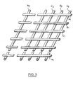
- the electrical insulating material is a plastic material in the form of a grid whose thickness is less than 5 mm and whose mesh consists of two networks of parallel wires, these two networks being superimposed, crossed, fixed one on the other at the contact points of the wires, the thickness of the wires of each network being the same.
- the two networks are fixed to each other by welding and the wires of the two networks have the same thickness.
- the distance between the wires of each network is between a few millimeters and a few centimeters.
- the wires in each network may not be parallel; their thickness may not be constant provided that after assembling the networks, the mesh has a constant maximum thickness at several points, less than about 5 mm.
- the cross section of the wires can be arbitrary, for example square, rectangular, circular, elliptical, trapezoidal.
- the plastic material can be, for example, polypropylene, polyethylene or polytetrafluoroethylene.
- Such plastic gratings have on the one hand a high vacuum rate, which allows easy circulation of the electrolysis solution between the two electrodes and on the other hand a relatively small contact surface with the electrodes, which avoids an excessive reduction in their active surface.
- a fabric As other materials separating the two electrodes, it is possible to use, within the framework of the present invention, a fabric, a canvas or a porous material of constant thickness such as for example a ceramic or a felt.
- the renewal of the electrolysis solution between the electrodes can, for example, be ensured by mechanical agitation or by forced circulation using a pump, for example.
- the active surface of the consumable electrode opposite the active surface of the other electrode dissolves.
- the consumable electrode therefore descends gradually, by gravity, under the simple effect of its own weight.
- the dissolution being stronger at the locations closest to the non-consumable electrode, the consumable electrode tends to conform as best as possible to the shape of the non-consumable electrode, which limits the risks of irregular dissolution.
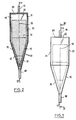
- the electrolysis cell shown in Figures 1 and 2 comprises a tank whose bottom wall is formed by the cathode 12, which is not consumable.
- the active surface of the non-consumable electrode 12 is conical, the tip of the cone being directed downwards. This active surface has at all points a constant inclination of 15 degrees relative to the direction 19 which is that of the axis of the cone. For the cell shown in Figures 1 and 2 this axis is vertical.
- the upper wall 21 of the tank is cylindrical and extends the cone so that the cylinder and the cone have the same axis, the diameter of the cylinder being the same as that of the base circle of the cone.
- the walls 20 and 21 are made of an electrical insulating material or internally covered with an electrical insulator 11, for example a paint or any other electrically insulating coating.
- the anode 14 consists of a stack of cylindrical solid metal ingots whose diameter is slightly less than that of the cylindrical wall 21 of the tank. It is applied under the sole effect of its own weight against the cathode 12 which, alone, ensures the maintenance of the anode 14.
- the anode 14 and the cathode 12 are separated by a plastic material 15 in the form of a mesh such as that shown in FIG. 3.
- the mesh consists of two networks of parallel wires A 1 B 1 C 1 ... N 1 of part and A 2 8 2 C Z ... N 2 on the other hand.
- the wires of these two networks are cylindrical, with a diameter of 1 mm. The distance between the wires is 1 cm.
- the two networks are superimposed, crossed at right angles and welded to the contact points of the wires.
- the electrolysis solution 16 circulates from bottom to top in the cell. Pipes 18 allow the arrival and the exit of this solution 16, in the direction of the arrows 17.
- the inlet pipe extends the tip of the cathode 12 along the axis of the cell.
- the electrodes 12 and 14 are supplied with electric current by a DC voltage source, not shown in FIGS. 1 and 2.
- the active surface of the non-consumable electrode 12 When the axis of the cell is rotated by an alpha angle around the tip of the cone, the active surface of the non-consumable electrode 12 always has at all its points a constant inclination of 15 degrees relative to the direction D represented by the axis of the cell and any straight line of direction D passing through any point of the consumable anode 14 crosses the active surface of the non-consumable cathode 12.
- First of all alpha must be less than 45 degrees in the context of the present invention.
- the inclination of the active surface of the non-consumable electrode 12 is between (15 + alpha) and 115-alphal.
- the inclination relative to the vertical must be less than 45 degrees, that is to say for this particular embodiment, that alpha must be less than 30 degrees. Otherwise, there may be significant anomalies in the functioning of the cell.
- the upper wall 20 of the electrolysis cell according to the invention is removable or has a part removable so as to allow the introduction of massive metal blocks.
- FIG. 4 A complete installation allowing the continuous electrolysis of a solution is schematically represented in FIG. 4.
- It consists of a closed circuit comprising a jacketed reactor 51 allowing the loading and recovery of the products, an electrolysis cell 52 and a pump 53 allowing the circulation of the electrolysis solution in the circuit.
- the lower part of the reactor 51 is connected to the lower part (inlet) of the cell 52 and the outlet of the cell 52 is connected to the upper part of the reactor 51.
- the jacketed reactor 51 is cooled by a circulation of water, symbolized by the arrows 54.
- the cell 52 shown diagrammatically in FIG. 4 is that shown in FIGS. 1 and 2.
- the present invention also relates to the use of the new electrolysis cells described above, provided with an anode consumable in a metal chosen from the group formed by magnesium, zinc, aluminum and their alloys for electrosynthesis. in an organic solvent medium of organic compounds chosen from the group consisting of carboxylic acids, alcohols, ketones and aldehydes by electrochemical reduction of organic halides.
- an electrolysis cell is used provided with an anode consumable in a metal chosen from the group formed by magnesium and its alloys for the electrosynthesis of carboxylic acids by electrochemical reduction of organic halides in the presence of carbon dioxide.
- aromatic chains mention may, for example, be made of substituted or unsubstituted phenyl, thiophene, furan and pyridine rings.
- the carboxyl group can as well be linked to an aliphatic carbon as to a carbon of an aromatic ring.
- the use of a magnesium anode provides the best results. In particular, tests have been carried out with an anode either of aluminum or of zinc, all other conditions identical elsewhere. The yields are then lower than those obtained with the magnesium anode.
- the organic solvents used are the low protein solvents usually used in organic electrochemistry, such as hexamethylphosphorotriamide (HMPT) letetrahydrofuran (THF), N-methylpyrolidone (NMP), dimethylformamide (DMF).
- the organic solvent conventionally contains an indifferent electrolyte such as tetrabutylammonium tetrafluoroborate (BF 4 NBu 4 ) or lithium perchlorate.
- an indifferent electrolyte such as tetrabutylammonium tetrafluoroborate (BF 4 NBu 4 ) or lithium perchlorate.
- the yields obtained in the carboxylate formed are high, very often greater than 99%.
- the yields of isolated carboxylic acid vary from 70 to 90% of the yield of carboxylate formed.
- an electrolysis cell is used provided with an anode consumable in a metal chosen from the group formed by magnesium, zinc, aluminum and their alloys for the electrosynthesis of alcohols, by electrochemical reduction. of organic halides having an atom or a functional group stabilizing carbanions attached to the carbon carrying the halogen, in the presence of carbonyl derivatives.
- the latter can be aldehydes as well as ketones; the yields are high and the implementation relatively simple.
- the organic halides have at least one atom or a functional group stabilizing carbanions, attached to the carbon carrying the halogen, that is to say located in the alpha position relative to the halogen.
- atoms and functional groups which stabilize carbanions are well known to those skilled in the art. Mention may be made, for example, of halogens, ester, ketone, allyl, benzene, alkoxy or nitrile groups.
- benzyl chloride By way of illustration and without limitation, mention may be made, for example, of benzyl chloride, benzyl bromide, allyl chloride, 3-chloro 2 methyl propene, 3-chloro 1 butene, 1-chloro 1-methyl ethyl acetate, carbon tetrachloride, dichlorophenylmethane, 1-phenyl 3-chloro propene and 1-methyl 3-chloropropene.
- R, and R 2 together with the carbon atom to which they are attached, form a ring, saturated or unsaturated, substituted or unsubstituted, optionally comprising one or more heteroatoms such as nitrogen, oxygen , phosphorus or sulfur.
- heteroatoms such as nitrogen, oxygen , phosphorus or sulfur.
- the alcohols obtained according to the process which is the subject of the present invention correspond to the general formula wherein R, R, and R 2 have the above meaning.
- organic solvents and the indifferent electrolytes used are the same as those mentioned above for the synthesis of carboxylic acids.
- DMF is used as solvent and the electrolysis is carried out at a temperature between -20 ° C. and + 30 ° C.
- an electrolysis cell is used provided with an anode consumable in a metal chosen from the group formed by magnesium, zinc, aluminum and their alloys for the electrosynthesis of ketones and aldehydes by electrochemical reduction of organic halides in the presence of organic acid anhydrides.
- a metal chosen from the group formed by magnesium, zinc, aluminum and their alloys for the electrosynthesis of ketones and aldehydes by electrochemical reduction of organic halides in the presence of organic acid anhydrides.
- the implementation is simple and the mass and faradaic yields high.
- R 3 has an aliphatic chain substituted with at least one aromatic group, for example in benzyl chloride, benzyl bromide, 1-phenyl 1-chloro ethane and 1-phenyl 1-chloro propane.
- R 3 can carry non-electro-reducible functions or more difficult to reduce than the R 3 -X bond, under the experimental conditions of electrosynthesis.
- non-electroreducible functions are, for example, the cyano, ether, sulfide or ester functions.
- R s represents a group OR s
- the corresponding anhydrides are then mixed anhydrides of carboxylic acids and carbonic acid. In the other cases, they are anhydrous carboxylic acids.
- R 4 and R 5 can carry non-electro-reducible functions, or more difficult to reduce than the bond R 3 ⁇ X, under the experimental conditions of electrosynthesis, and none of the functions carried by R 3 or R 4 does must be more electrophilic than the anhydride function itself.
- R 4 and R 5 represent a linear or branched alkyl chain.
- R 4 and R s are identical.
- R 4 and R s are identical and represent an alkyl chain, linear or branched, as is the case for example for acetic anhydride.
- organic solvents and the indifferent electrolytes used are the same as those mentioned above for the synthesis of carboxylic acids.
- DMF is used as solvent.
- the direction D is to preferably the vertical direction.
- the cathode 12 made of stainless steel, is a cone with a height of 100 mm and a base diameter of 53 mm.
- the other walls of the tank are made of stainless steel and are internally covered with an inert electrical insulating coating 11.
- the anode 14 consists of a stack of cylindrical aluminum blocks with a diameter of 50 mm and a height of 100 mm.
- the plastic material 15 in the form of a mesh is polypropylene. This mesh is just placed on the active surface of the cathode 12, the shape of which it matches, before the introduction of the anode 14.
- the lower aluminum block was machined so that it is approximately in the form of a cone with a height of 100 mm and a base diameter of 50 mm, which is easily achieved from of a cylindrical block having these dimensions.
- the machined block which introduces the shape of the cathode is introduced, then several other blocks are stacked on this lower block up to the top of the cell.
- the dimethylbenzylcarbinol formed is isolated, and identified according to the usual methods, well known to those skilled in the art.
- the alcohol formed was isolated after hydrolysis of the solution using an aqueous solution of ammonium chloride and extraction with ether. After evaporation of the ether, the crude alcohol was purified by distillation. The pure alcohol thus isolated (purity verified by CPG) is identified by its NMR and IR spectra.
- the yield of distilled dimethylbenzylcarbinol obtained is 60% (purity greater than 95%).
- the intensity of the current is fixed at the start at 2.5 A since the optimal operating conditions are then already met, the anode being in the optimal position relative to the cathode.
- Example 1 The same test is carried out as that of Example 1 but without machining the lower block before the first electrolysis. The same result is obtained but the operating equilibrium is much longer to reach.
Landscapes
- Chemical & Material Sciences (AREA)
- Organic Chemistry (AREA)
- Engineering & Computer Science (AREA)
- Chemical Kinetics & Catalysis (AREA)
- Electrochemistry (AREA)
- Materials Engineering (AREA)
- Metallurgy (AREA)
- Electrolytic Production Of Non-Metals, Compounds, Apparatuses Therefor (AREA)
- Electrodes For Compound Or Non-Metal Manufacture (AREA)
Claims (12)
Priority Applications (1)
| Application Number | Priority Date | Filing Date | Title |
|---|---|---|---|
| AT86401895T ATE54472T1 (de) | 1985-09-05 | 1986-08-29 | Organische elektrolysezelle mit verbrauchselektrode. |
Applications Claiming Priority (2)
| Application Number | Priority Date | Filing Date | Title |
|---|---|---|---|
| FR8513188A FR2586710B1 (fr) | 1985-09-05 | 1985-09-05 | Cellule d'electrolyse organique a electrode consommable |
| FR8513188 | 1985-09-05 |
Publications (2)
| Publication Number | Publication Date |
|---|---|
| EP0219367A1 EP0219367A1 (de) | 1987-04-22 |
| EP0219367B1 true EP0219367B1 (de) | 1990-07-11 |
Family
ID=9322650
Family Applications (1)
| Application Number | Title | Priority Date | Filing Date |
|---|---|---|---|
| EP86401895A Expired - Lifetime EP0219367B1 (de) | 1985-09-05 | 1986-08-29 | Organische Elektrolysezelle mit Verbrauchselektrode |
Country Status (6)
| Country | Link |
|---|---|
| US (1) | US4686018A (de) |
| EP (1) | EP0219367B1 (de) |
| JP (1) | JPH07122155B2 (de) |
| AT (1) | ATE54472T1 (de) |
| DE (1) | DE3672556D1 (de) |
| FR (1) | FR2586710B1 (de) |
Families Citing this family (22)
| Publication number | Priority date | Publication date | Assignee | Title |
|---|---|---|---|---|
| IT1203373B (it) * | 1987-03-18 | 1989-02-15 | Silvestri Silvestri | Dispositivo per la trasformazione di celle elettrolitiche di tipo filtro pressa in celle ad elettrodi sacrificali rinnovabili in continuo |
| FR2617197B1 (fr) * | 1987-06-25 | 1991-07-12 | Poudres & Explosifs Ste Nale | Cellule d'electrolyse a electrodes bipolaires consommables |
| FR2624884B1 (fr) * | 1987-12-18 | 1990-04-20 | Poudres & Explosifs Ste Nale | Procede de synthese electrochimique de cetones alpha saturees |
| US4834858A (en) * | 1988-03-23 | 1989-05-30 | Montvale Process Company, Inc. | Electrolytic reactor |
| DE3813017A1 (de) * | 1988-04-19 | 1989-11-02 | Wiederaufarbeitung Von Kernbre | Vorrichtung zur elektrochemischen behandlung von radioaktiven brennstoffloesungen |
| FR2639364B1 (fr) * | 1988-11-23 | 1990-12-28 | Poudres & Explosifs Ste Nale | Procede d'electrosynthese d'aldehydes |
| FR2646441B1 (fr) * | 1989-04-28 | 1991-07-12 | Poudres & Explosifs Ste Nale | Procede d'electrosynthese d'un ester beta gamma insature |
| FR2688519A1 (fr) * | 1992-03-12 | 1993-09-17 | Poudres & Explosifs Ste Nale | Procede d'electrosynthese de fluorobiphenyles symetriques. |
| US6147216A (en) * | 1993-06-25 | 2000-11-14 | Merrell Pharmaceuticals Inc. | Intermediates useful for the preparation of antihistaminic piperidine derivatives |
| EP2261208A1 (de) | 1993-06-25 | 2010-12-15 | Aventisub II Inc. | Zwischenprodukte zur Herstellung antihistaminischer 4-Diphenylmethyl-/Diphenylmethoxy- Piperidinderivate |
| DE4429354A1 (de) | 1994-08-18 | 1996-02-22 | Hoechst Ag | Elektrolysezelle mit Verzehranoden |
| US6683094B2 (en) | 1998-07-02 | 2004-01-27 | Aventis Pharmaceuticals Inc. | Antihistaminic piperidine derivatives and intermediates for the preparation thereof |
| US6700012B2 (en) | 1998-07-02 | 2004-03-02 | Aventis Pharmaceuticals Inc. | Antihistaminic piperidine derivatives and intermediates for the preparation thereof |
| EP1046616A3 (de) * | 1999-02-06 | 2001-03-21 | Vallendar, Hubertus | Elektrodenanordnung zur galvanischen Behandlung von strömenden Medien |
| FR2795749B1 (fr) * | 1999-07-02 | 2001-10-05 | Electricite De France | Reacteur electrochimique a electrode consommable rotative |
| US20080116144A1 (en) * | 2006-10-10 | 2008-05-22 | Spicer Randolph, Llc | Methods and compositions for reducing chlorine demand, decreasing disinfection by-products and controlling deposits in drinking water distribution systems |
| US20130206664A1 (en) * | 2010-10-22 | 2013-08-15 | Tae Gyo Kim | Metal ion sterilization device |
| KR101239206B1 (ko) * | 2011-05-06 | 2013-03-05 | 김태규 | 금속 이온 살균장치 |
| US8617403B1 (en) | 2013-06-25 | 2013-12-31 | Blue Earth Labs, Llc | Methods and stabilized compositions for reducing deposits in water systems |
| DE102016109822A1 (de) * | 2016-05-27 | 2017-11-30 | Fraunhofer-Gesellschaft zur Förderung der angewandten Forschung e.V. | Elektrolytischer Reaktor |
| US10837116B2 (en) * | 2017-11-27 | 2020-11-17 | Fraunhofer-Gesellschaft Zur Foerderung Der Angewandten Forschung E.V. | Electrolytic reactor |
| CN113278996A (zh) * | 2021-04-01 | 2021-08-20 | 安徽海康药业有限责任公司 | 一种2,4,5-三氟苯乙酸的制备方法 |
Family Cites Families (5)
| Publication number | Priority date | Publication date | Assignee | Title |
|---|---|---|---|---|
| US982037A (en) * | 1909-09-30 | 1911-01-17 | Mcdonald Electrolytic Company | Electrolytic cell. |
| US1278723A (en) * | 1914-08-19 | 1918-09-10 | Frank H Nickle | Electrolytic cell. |
| BE606111A (de) * | 1960-07-13 | |||
| FR1412239A (fr) * | 1963-10-23 | 1965-09-24 | Chimica Dell Aniene S P A Soc | Cellule d'électrolyse à électrodes multiples réglables |
| SU1046022A1 (ru) * | 1982-06-07 | 1983-10-07 | Новочеркасский Ордена Трудового Красного Знамени Политехнический Институт Им.Серго Орджоникидзе | Анодное устройство дл получени металлических порошков |
-
1985
- 1985-09-05 FR FR8513188A patent/FR2586710B1/fr not_active Expired - Lifetime
-
1986
- 1986-08-29 DE DE8686401895T patent/DE3672556D1/de not_active Expired - Lifetime
- 1986-08-29 EP EP86401895A patent/EP0219367B1/de not_active Expired - Lifetime
- 1986-08-29 AT AT86401895T patent/ATE54472T1/de not_active IP Right Cessation
- 1986-09-02 US US06/904,025 patent/US4686018A/en not_active Expired - Lifetime
- 1986-09-05 JP JP61208089A patent/JPH07122155B2/ja not_active Expired - Fee Related
Also Published As
| Publication number | Publication date |
|---|---|
| JPS6256589A (ja) | 1987-03-12 |
| US4686018A (en) | 1987-08-11 |
| FR2586710B1 (fr) | 1990-03-30 |
| FR2586710A1 (fr) | 1987-03-06 |
| DE3672556D1 (de) | 1990-08-16 |
| ATE54472T1 (de) | 1990-07-15 |
| EP0219367A1 (de) | 1987-04-22 |
| JPH07122155B2 (ja) | 1995-12-25 |
Similar Documents
| Publication | Publication Date | Title |
|---|---|---|
| EP0219367B1 (de) | Organische Elektrolysezelle mit Verbrauchselektrode | |
| EP0277048B1 (de) | Verfahren zur elektrochemischen Herstellung von Carbonsäuren | |
| FR2810996A1 (fr) | Procede d'electrolyse | |
| FR2538005A1 (fr) | Cathode pour la production electrolytique d'hydrogene et son utilisation | |
| FR2646441A1 (fr) | Procede d'electrosynthese d'un ester beta gamma insature | |
| CN1058302C (zh) | 2-苯并[c]呋喃酮类化合物的制备方法 | |
| CH664979A5 (fr) | Procede d'electrosynthese d'acides carboxyliques. | |
| EP0198743B1 (de) | Verfahren zur Elektrosynthese von Ketonen | |
| FR2617197A1 (fr) | Cellule d'electrolyse a electrodes bipolaires consommables | |
| FR2606427A1 (fr) | Procede d'electrosynthese d'aryl alkyl phosphines tertiaires | |
| BE1014628A5 (fr) | Procede de preparation de composes perfluoroorganiques par fluoration electrochimique. | |
| EP0201365B1 (de) | Verfahren zur Elektrosynthese von Alkoholen und Epoxidverbindungen | |
| EP0370866B1 (de) | Verfahren zur Elektrosynthese von Aldehyden | |
| US4022672A (en) | Electrochemical synthesis of insecticide intermediates | |
| EP0230171B1 (de) | Verfahren und Vorrichtung zur kontinuierlichen Herstellung von Lithium durch Elektrolyse von Lithiumchlorid | |
| BE1014521A3 (fr) | Procede de preparation de composes organiques perfluores par fluoration electrochimique. | |
| CA1202596A (fr) | Procede pour la preparation continue de lithium par electrolyse du chlorure de lithium dans un melange de sels fondus et appareillage pour la mise en oeuvre dudit procede | |
| FR2795749A1 (fr) | Reacteur electrochimique a electrode consommable rotative | |
| KR100516422B1 (ko) | 프탈라이드의 제조 방법 | |
| FR2753726A1 (fr) | Reacteur electrochimique a anode volumique consommable pour la synthese organique | |
| US5567299A (en) | Process for the electrochemical oxidation of arylketones | |
| US4659441A (en) | Process for preparing tetraalkyl 1,1,2,2-ethene-tetracarboxylate | |
| FR2653139A1 (fr) | Procede et dispositif d'introduction d'au moins un halogenure a l'etat liquide ou gazeux dans le bain d'une cellule d'electrolyse ignee. | |
| FR2656631A1 (fr) | Procede electrochimique de preparation de composes chalcogenes notamment aromatiques, electrode mise en óoeuvre dans ce procede et nouveaux composes chalcogenes ainsi obtenus. | |
| FR2632978A1 (fr) | Procede d'electrosynthese de carbinols benzyliques |
Legal Events
| Date | Code | Title | Description |
|---|---|---|---|
| PUAI | Public reference made under article 153(3) epc to a published international application that has entered the european phase |
Free format text: ORIGINAL CODE: 0009012 |
|
| AK | Designated contracting states |
Kind code of ref document: A1 Designated state(s): AT BE CH DE FR GB IT LI LU NL SE |
|
| 17P | Request for examination filed |
Effective date: 19871012 |
|
| 17Q | First examination report despatched |
Effective date: 19890508 |
|
| GRAA | (expected) grant |
Free format text: ORIGINAL CODE: 0009210 |
|
| AK | Designated contracting states |
Kind code of ref document: B1 Designated state(s): AT BE CH DE FR GB IT LI LU NL SE |
|
| REF | Corresponds to: |
Ref document number: 54472 Country of ref document: AT Date of ref document: 19900715 Kind code of ref document: T |
|
| ITF | It: translation for a ep patent filed | ||
| GBT | Gb: translation of ep patent filed (gb section 77(6)(a)/1977) | ||
| REF | Corresponds to: |
Ref document number: 3672556 Country of ref document: DE Date of ref document: 19900816 |
|
| PLBE | No opposition filed within time limit |
Free format text: ORIGINAL CODE: 0009261 |
|
| STAA | Information on the status of an ep patent application or granted ep patent |
Free format text: STATUS: NO OPPOSITION FILED WITHIN TIME LIMIT |
|
| 26N | No opposition filed | ||
| ITTA | It: last paid annual fee | ||
| EPTA | Lu: last paid annual fee | ||
| EAL | Se: european patent in force in sweden |
Ref document number: 86401895.7 |
|
| REG | Reference to a national code |
Ref country code: GB Ref legal event code: IF02 |
|
| PGFP | Annual fee paid to national office [announced via postgrant information from national office to epo] |
Ref country code: BE Payment date: 20030528 Year of fee payment: 18 |
|
| PGFP | Annual fee paid to national office [announced via postgrant information from national office to epo] |
Ref country code: FR Payment date: 20030710 Year of fee payment: 18 |
|
| PGFP | Annual fee paid to national office [announced via postgrant information from national office to epo] |
Ref country code: SE Payment date: 20030806 Year of fee payment: 18 |
|
| PGFP | Annual fee paid to national office [announced via postgrant information from national office to epo] |
Ref country code: LU Payment date: 20030811 Year of fee payment: 18 Ref country code: AT Payment date: 20030811 Year of fee payment: 18 |
|
| PGFP | Annual fee paid to national office [announced via postgrant information from national office to epo] |
Ref country code: GB Payment date: 20030827 Year of fee payment: 18 |
|
| PGFP | Annual fee paid to national office [announced via postgrant information from national office to epo] |
Ref country code: NL Payment date: 20030831 Year of fee payment: 18 |
|
| PGFP | Annual fee paid to national office [announced via postgrant information from national office to epo] |
Ref country code: DE Payment date: 20031030 Year of fee payment: 18 |
|
| PGFP | Annual fee paid to national office [announced via postgrant information from national office to epo] |
Ref country code: CH Payment date: 20031104 Year of fee payment: 18 |
|
| NLT1 | Nl: modifications of names registered in virtue of documents presented to the patent office pursuant to art. 16 a, paragraph 1 |
Owner name: SNPE |
|
| PG25 | Lapsed in a contracting state [announced via postgrant information from national office to epo] |
Ref country code: LU Free format text: LAPSE BECAUSE OF NON-PAYMENT OF DUE FEES Effective date: 20040829 Ref country code: GB Free format text: LAPSE BECAUSE OF NON-PAYMENT OF DUE FEES Effective date: 20040829 Ref country code: AT Free format text: LAPSE BECAUSE OF NON-PAYMENT OF DUE FEES Effective date: 20040829 |
|
| PG25 | Lapsed in a contracting state [announced via postgrant information from national office to epo] |
Ref country code: SE Free format text: LAPSE BECAUSE OF NON-PAYMENT OF DUE FEES Effective date: 20040830 |
|
| PG25 | Lapsed in a contracting state [announced via postgrant information from national office to epo] |
Ref country code: LI Free format text: LAPSE BECAUSE OF NON-PAYMENT OF DUE FEES Effective date: 20040831 Ref country code: CH Free format text: LAPSE BECAUSE OF NON-PAYMENT OF DUE FEES Effective date: 20040831 Ref country code: BE Free format text: LAPSE BECAUSE OF NON-PAYMENT OF DUE FEES Effective date: 20040831 |
|
| BERE | Be: lapsed |
Owner name: *SNPE Effective date: 20040831 |
|
| PG25 | Lapsed in a contracting state [announced via postgrant information from national office to epo] |
Ref country code: NL Free format text: LAPSE BECAUSE OF NON-PAYMENT OF DUE FEES Effective date: 20050301 Ref country code: DE Free format text: LAPSE BECAUSE OF NON-PAYMENT OF DUE FEES Effective date: 20050301 |
|
| EUG | Se: european patent has lapsed | ||
| REG | Reference to a national code |
Ref country code: CH Ref legal event code: PL |
|
| GBPC | Gb: european patent ceased through non-payment of renewal fee |
Effective date: 20040829 |
|
| PG25 | Lapsed in a contracting state [announced via postgrant information from national office to epo] |
Ref country code: FR Free format text: LAPSE BECAUSE OF NON-PAYMENT OF DUE FEES Effective date: 20050429 |
|
| NLV4 | Nl: lapsed or anulled due to non-payment of the annual fee |
Effective date: 20050301 |
|
| REG | Reference to a national code |
Ref country code: FR Ref legal event code: ST |
|
| PG25 | Lapsed in a contracting state [announced via postgrant information from national office to epo] |
Ref country code: IT Free format text: LAPSE BECAUSE OF NON-PAYMENT OF DUE FEES;WARNING: LAPSES OF ITALIAN PATENTS WITH EFFECTIVE DATE BEFORE 2007 MAY HAVE OCCURRED AT ANY TIME BEFORE 2007. THE CORRECT EFFECTIVE DATE MAY BE DIFFERENT FROM THE ONE RECORDED. Effective date: 20050829 |
|
| BERE | Be: lapsed |
Owner name: *SNPE Effective date: 20040831 |