EP0217366A2 - Méthode pour la mise en place d'un ancrage de traction ou de compression au dessous du niveau de l'eau pour l'ancrage d'un rideau de palplanches ou similaires - Google Patents
Méthode pour la mise en place d'un ancrage de traction ou de compression au dessous du niveau de l'eau pour l'ancrage d'un rideau de palplanches ou similaires Download PDFInfo
- Publication number
- EP0217366A2 EP0217366A2 EP86113464A EP86113464A EP0217366A2 EP 0217366 A2 EP0217366 A2 EP 0217366A2 EP 86113464 A EP86113464 A EP 86113464A EP 86113464 A EP86113464 A EP 86113464A EP 0217366 A2 EP0217366 A2 EP 0217366A2
- Authority
- EP
- European Patent Office
- Prior art keywords
- sheet pile
- carriage
- pile wall
- drill
- holding device
- Prior art date
- Legal status (The legal status is an assumption and is not a legal conclusion. Google has not performed a legal analysis and makes no representation as to the accuracy of the status listed.)
- Granted
Links
Images
Classifications
-
- E—FIXED CONSTRUCTIONS
- E02—HYDRAULIC ENGINEERING; FOUNDATIONS; SOIL SHIFTING
- E02D—FOUNDATIONS; EXCAVATIONS; EMBANKMENTS; UNDERGROUND OR UNDERWATER STRUCTURES
- E02D5/00—Bulkheads, piles, or other structural elements specially adapted to foundation engineering
- E02D5/74—Means for anchoring structural elements or bulkheads
- E02D5/76—Anchorings for bulkheads or sections thereof in as much as specially adapted therefor
-
- E—FIXED CONSTRUCTIONS
- E02—HYDRAULIC ENGINEERING; FOUNDATIONS; SOIL SHIFTING
- E02D—FOUNDATIONS; EXCAVATIONS; EMBANKMENTS; UNDERGROUND OR UNDERWATER STRUCTURES
- E02D5/00—Bulkheads, piles, or other structural elements specially adapted to foundation engineering
- E02D5/74—Means for anchoring structural elements or bulkheads
- E02D5/80—Ground anchors
- E02D5/808—Ground anchors anchored by using exclusively a bonding material
Definitions
- the invention relates to a method for setting a tension or pressure anchor with a rod, wire or tubular anchor element below a water level for anchoring a sheet pile wall, diaphragm wall, quay wall or the like, with a holding device for a first on the sheet pile wall at the level of the bore to be produced Drill mount attached with an underwater drilling machine, then pierced the sheet pile wall and then the anchor element is inserted and anchored.
- a known device of this type is used to ram an anchor pole through a sheet pile wall.
- the holding device consists of a base plate, which is arranged obliquely at the end of the drill carriage in accordance with the desired drilling direction, preferably at an angle of 45 degrees to it, and is fixedly connected to the drill carriage (DE-PS 31 22 032).
- This device must be attached to the sheet pile by divers;
- the drilling machine is operated from above the water surface via a control unit which is connected to the drilling machine via hose lines.
- the sheet pile wall is first pierced by means of a tubular drill; the drill remains in the sheet pile wall and serves as a guide when ramming the anchor pile through the sheet pile wall.
- a disadvantage of this known method and the device is that a number of jobs can only be carried out by divers, furthermore that the drill is lost and that the ramming of the anchor pile, apart from the guidance through the short drill pipe, does not require any further guidance and therefore no control he follows. If the anchor pile encounters an obstacle when ramming in, the sheet pile must be pierced again.
- the object of the invention is to make a method of the type mentioned at the outset suitable for setting a tension or pressure anchor and to provide a device suitable for carrying it out, as a result of which the work to be carried out under water is reduced to a minimum or avoided entirely and the whole Drill to be recovered.
- this object is achieved procedurally in that after adjusting and attaching the holding device with the drill carriage, the free end of the carriage is raised by pivoting about a joint arranged on the holding device with a horizontal axis above the water level, at the end projecting above the water level the gun mount the drill with a first drill for drilling through the sheet pile and then the gun lowered into the drilling position and the sheet pile is pierced, that after the first drill has been withdrawn, the gun mount is raised again above the water level and a drill pipe for producing the borehole in full Mounted length, the carriage lowered back into the drilling position and the drill pipe is driven into the ground through the opening in the sheet pile wall and that after the insertion of the anchor element, the drill pipe with compression of the cavity between the anchor element and the borehole wall with hardening material ial pulled and disassembled after lifting the carriage above the water level.
- the anchor element can be inserted into the drill pipe at the same time as the drill hole is being made.
- the holding device is expediently held and adjusted hanging on tension members, for example threaded rods, ropes or the like, and is suitably fastened by clamping to the sheet pile wall.
- tension members for example threaded rods, ropes or the like
- the carriage can also be raised and lowered using a cable.
- the advantage of the method according to the invention is above all that the drilling machine, the drill pipe, the anchor element and, if appropriate, a holding crossmember and an anchor nut are mounted from land when the mount is folded up above the water level, and the mount is carried out in a simple manner using a cable into the Drilling position can be lowered. Holding and adjusting the holding device and its attachment to the sheet pile wall can also be done from land using cables and corresponding control units. Since the length of the drill carriage is greater than the length of the drill pipe or anchor element, it is not only possible to dispense with the otherwise necessary insertion of the drill pipe and anchor element, but possibly even insert the anchor element into the drill pipe from the outset and together with it into the ground be screwed in.
- a device which is particularly suitable for carrying out the method according to the invention with a holding device which is adjustable and attachable to the sheet pile wall or the like and a drill mount fastened thereon with guides for a drilling machine and a drill and / or a drill pipe is characterized in that The length of the drill pipe or the anchor element dimensioned mount on the holding device can be pivoted about a joint with a horizontal axis running parallel to the sheet pile wall and can be raised and lowered from land by means of a cable pull.
- the holding device is useful on tension members, e.g. Threaded rods, ropes or the like are suspended and can be raised and lowered from land and adjusted in front of the sheet pile wall.
- tension members e.g. Threaded rods, ropes or the like are suspended and can be raised and lowered from land and adjusted in front of the sheet pile wall.
- the joint can be designed to be detachable and vertical guide rails can be provided, along which the lower end of the mount can be raised above the water surface and lowered again.
- the holding device can be provided with pliers which can be actuated by means of hydraulic cylinder-piston units. Magnets or suction devices can also be provided for fastening the holding device to the sheet pile wall.
- the holding device expediently has guide bodies adapted to the contour of the sheet pile wall. The centering of the holding device on the sheet pile wall is thereby facilitated, the torque occurring during drilling is absorbed and security against horizontal displacements of the holding device is achieved.
- the mount is also pivotally mounted on the holding device about an articulation with an axis running at right angles to the drilling axis.
- the pivot axis of this bearing should at least approximately go through the center of the opening in the sheet pile wall.
- the arrangement of this joint in the immediate vicinity of the opening of the sheet pile wall and in such a way that its axis passes through the center of the opening and intersects the borehole axis has the advantage that it is possible to drill through the same opening in the sheet pile wall with different horizontal angles, for example if in an obstacle, such as a boulder, in the direction initially drilled, hinders the drilling process. This avoids further weakening of the sheet pile wall and the Accelerated work process.
- means can be provided on the holding device for pivoting the mount around the pivot axis running at right angles to the drilling axis and for fixing it in a specific position.
- These means are expediently hydraulic cylinder-piston units.
- a connecting strap can be arranged between the joint with the horizontal axis and that with the axis running at right angles to the drilling axis.
- the joint with a horizontal axis and the joint with an axis perpendicular to the drilling axis can also be combined in a ball joint.
- the mount can also be gimbaled on the holding device; in any case, the swivel axes should go through the center of the opening of the sheet pile wall.
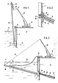
- a holding device 2 is prepared, which can be attached to the sheet pile wall 1 from the water side.
- a drill carriage 10 is pivotably mounted about a joint 3 with a horizontal axis running parallel to the sheet pile wall 1.
- the length of the mount 10 is selected so that it can accommodate the full length of the drill pipe 17 required for drilling the bore and the anchor element 12.
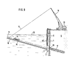
- the Holding device 2 with the carriage 10 by means of tension members 9, for example threaded rods, lowered from the surface of the terrain to the desired depth and fastened to the sheet pile wall 1.
- the carriage 10 is held at its upper end by means of a cable 13 which leads to a telescopic boom 18 on a crane vehicle 33.
- the drilling machine 14 is mounted from land, which can be moved along the carriage 10 by means of a carriage 15.
- the drilling machine 14 is designed in a manner known per se; it has a drill head and a drive motor. Behind the drill head there is a flushing head with a rod that is guided through the drill head. The flushing head can be moved along the carriage 10 independently of the drilling head.
- a drill 16 with which the sheet pile wall 1 can be pierced is first attached to the drilling machine 14. Then the carriage 10 is lowered into the drilling position by means of the cable 13; the drill 16 is thus aligned in the anchor axis 11, which also forms the drilling axis. Then the drill 14 with the drill 16 is e.g. pulled by means of a chain drive along the carriage 10 in the direction of the sheet pile wall 1 until the head of the drill 16 is on the sheet pile wall and pierces it. Then the drill 14 with the drill 16 is pulled back into the starting position, the mount is pivoted upwards about the joint 3 and the drill 16 is dismantled from the ground.
- the full length of the actual drill pipe 17 is then placed on the mount 10, aligned and connected to the drilling machine 14.
- the drilling pipe 17 is drilled with the aid of the drilling machine 14 through the opening 28 previously created in the sheet pile wall 1 into the soil formation 5 to the desired depth driven in.
- the head of the drilling machine 14 is detached from the drilling tube 17, the drilling machine 14 is pulled back into the starting position and the mount 10 is pivoted upwards again.
- An anchor element 12 e.g. an anchor rod, placed on the carriage 10 and aligned. At the bottom end of the anchor element 12 there is a claw device 20. Furthermore, a sealing plate 22 is fastened to the anchor element 12, which seals the cavity between the anchor element and the drill pipe 17, and a compression line 21, which is passed through the sealing plate 22. The anchor element 12 is held by the linkage of the flushing head. After the carriage 10 has been lowered again into the drilling position, the anchor element 12 is inserted into the drill pipe 17 by means of the drilling machine 14 until it has reached its desired position.
- an anchor element 12 e.g. an anchor rod
- the length of the mount 10 is greater than the length of the anchor element 12, it can be inserted into the drill pipe 17 beforehand and at the same time screwed into the bottom formation 5.
- the head of the drilling machine 14 is then coupled again to the drilling pipe 17 in order to be able to pull it.
- This situation is shown in Fig. 2.
- the drill pipe 17 is initially moved back only a short distance while the flushing head, which holds the armature 12, remains standing.
- the anchor element 12 sits firmly in the ground.
- the cavity between the anchor element 12 and the borehole wall is then continuously filled with a grout, for example cement mortar, until it has reached the sealing plate 22 via the grouting line 21.
- the grout thus forms a grout 31.
- the carriage 10 is pivoted up by means of the cable 13 and the drill pipe 17 is dismantled.
- a traverse 19 e.g. fixed, aligned and adjusted in the form of a prefabricated concrete component. After lowering the carriage 10 again into the drilling position, this cross member 19 can be moved in the direction of the anchor element 12 by means of the drilling machine and pushed over it. The cross member 19 thus extends a certain distance into the opening 28 in the sheet pile wall 1 (FIG. 3).
- the drilling machine 14 After loosening the connection between the traverse 19 and the drilling machine 14, the drilling machine 14 is moved back into its starting position. An anchor nut 23 can then be introduced in the same way and screwed onto the air-side end of the anchor element 12 if this work is not done by divers. A possible cavity behind the sheet pile wall 1 can in turn be pressed with grout 32 through openings in the cross member 19 and the anchor head can be sealed in this way.
- the holding device After the connection between the holding device 2 and the sheet pile wall has been released, the holding device is recovered. If the anchor is a tie rod, the anchor element 12 can be tensioned after the compression body 31 has completely hardened.
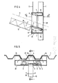
- the holding device 2 consists of a housing 26 which is at least partially open to the sheet pile wall 1 and in which four tongs 7 which can be actuated by hydraulic cylinder-piston units 8 are provided.
- the position of the outer legs of the pliers 7 is adapted to the slope of the individual sheet piles of the sheet pile wall 1 and roughened or serrated on their inner surfaces in order to achieve good contact with the sheet pile wall 1.
- the pliers 7 only serve to fix the holding device 2 to the sheet pile wall 1; their weight and that of the carriage 10 is carried by the tension members 9, which lead to corresponding anchoring on the surface of the site.
- the holding device 2 is equipped on its side facing the sheet pile wall with the profile of the sheet pile adapted guide bodies 24, which facilitate the centering of the holding device and support the transmission of the torque occurring during drilling to the sheet pile wall 1 or relieve the pliers 7.
- the mount 10 is connected via a joint 3 with a horizontal axis running parallel to the sheet pile wall 1 to a bracket 27, which in turn is mounted on the housing 26 via a joint 4 with an axis running in a vertical plane perpendicular to the drilling axis 11.
- the mount 10 can be pivoted in the vertical direction (arrow 29 in FIG. 4) by means of the joint 3 and in the horizontal direction (arrow 30 in FIG. 5) by means of the joint 4.
- the pivoting of the carriage 10 in the vertical direction (arrow 29) takes place, as already described, by means of the cable 13; for pivoting in the horizontal direction (arrow 30), a cylinder-piston unit 6 is arranged on the bracket 27, which is supported against the housing 26 of the holding device 2.
- the extension of the axis of the joint 4 runs through the center of the opening 28 created in the sheet pile wall 1 and intersects the drilling axis 11 there (FIG. 4). This makes it possible to make several holes with different horizontal angles through the same opening 28, for example when a hole has to be abandoned due to an obstacle in the course of the drilling axis.
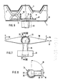
- FIGS. 6 to 8 Another exemplary embodiment for the articulated mounting of the mount on the holding device 2 is shown in FIGS. 6 to 8.
- the ball joint 34 consists of a ball 36 fastened to the mount 10 via a pin 35, which ball 36 can be rotated in a pan 37 designed as a partially hollow ball.
- the pan 37 is mounted on a link 38 which is articulated at both ends to cylinder-piston units 39; the cylinder-piston units 39 are in turn attached to the housing 26 of the holding device 2.
- the cylinder-piston units 39 serve to support the pressure of the carriage 10, while a pivoting movement in the horizontal direction is brought about by a cylinder-piston unit 6 '.
- the movement possibilities of the carriage in the vertical and horizontal directions are again indicated by arrows 29 and 30, respectively.
Landscapes
- Engineering & Computer Science (AREA)
- Structural Engineering (AREA)
- Life Sciences & Earth Sciences (AREA)
- General Life Sciences & Earth Sciences (AREA)
- Mining & Mineral Resources (AREA)
- Paleontology (AREA)
- Civil Engineering (AREA)
- General Engineering & Computer Science (AREA)
- Bulkheads Adapted To Foundation Construction (AREA)
- Piles And Underground Anchors (AREA)
- Placing Or Removing Of Piles Or Sheet Piles, Or Accessories Thereof (AREA)
- Revetment (AREA)
- Foundations (AREA)
Priority Applications (1)
| Application Number | Priority Date | Filing Date | Title |
|---|---|---|---|
| AT86113464T ATE48162T1 (de) | 1985-10-03 | 1986-10-01 | Verfahren zum setzen eines zug- oder druckankers unterhalb eines wasserspiegels zum verankern einer spundwand oder dergleichen. |
Applications Claiming Priority (2)
| Application Number | Priority Date | Filing Date | Title |
|---|---|---|---|
| DE19853535319 DE3535319A1 (de) | 1985-10-03 | 1985-10-03 | Verfahren und vorrichtung zum verankern von wenigstens teilweise unter wasser befindlichen spundwaenden |
| DE3535319 | 1985-10-03 |
Publications (3)
| Publication Number | Publication Date |
|---|---|
| EP0217366A2 true EP0217366A2 (fr) | 1987-04-08 |
| EP0217366A3 EP0217366A3 (en) | 1988-01-20 |
| EP0217366B1 EP0217366B1 (fr) | 1989-11-23 |
Family
ID=6282665
Family Applications (1)
| Application Number | Title | Priority Date | Filing Date |
|---|---|---|---|
| EP86113464A Expired EP0217366B1 (fr) | 1985-10-03 | 1986-10-01 | Méthode pour la mise en place d'un ancrage de traction ou de compression au dessous du niveau de l'eau pour l'ancrage d'un rideau de palplanches ou similaires |
Country Status (8)
| Country | Link |
|---|---|
| US (1) | US4711604A (fr) |
| EP (1) | EP0217366B1 (fr) |
| JP (1) | JPS62174417A (fr) |
| AT (1) | ATE48162T1 (fr) |
| CA (1) | CA1255917A (fr) |
| DE (2) | DE3535319A1 (fr) |
| ES (1) | ES2012331B3 (fr) |
| GR (1) | GR3000355T3 (fr) |
Cited By (1)
| Publication number | Priority date | Publication date | Assignee | Title |
|---|---|---|---|---|
| CN111425231A (zh) * | 2020-03-31 | 2020-07-17 | 中国矿业大学 | 一种长短锚索协调吸能让压装置及施工方法 |
Families Citing this family (11)
| Publication number | Priority date | Publication date | Assignee | Title |
|---|---|---|---|---|
| EP0491964B1 (fr) * | 1990-07-24 | 1995-03-15 | Sunearth Co., Ltd. | Appareil d'injection d'un fluide de conditionnement du sol |
| DE19525590C2 (de) * | 1995-07-13 | 1999-04-29 | Zueblin Ag | Herstellung einer Baugrube mit Verankerungen unterhalb des Grundwasserspiegels |
| DE19527608C2 (de) * | 1995-07-28 | 1999-02-11 | Bauer Spezialtiefbau | Unterwasser-Verbundpfähle |
| US7517175B2 (en) * | 2003-07-11 | 2009-04-14 | Timmerman James E | Method for maintaining seawalls |
| US6908258B2 (en) * | 2003-07-11 | 2005-06-21 | James E. Timmerman | Methods and apparatus for maintaining seawalls |
| WO2008002308A2 (fr) * | 2006-06-28 | 2008-01-03 | Timmerman James E | Procédés, systèmes et appareil de retenue de digues |
| IT1392228B1 (it) * | 2008-12-03 | 2012-02-22 | Melegari | Procedimento per il consolidamento e/o il rinforzo di banchine portuali |
| CA2957748C (fr) | 2017-02-13 | 2018-05-01 | Lyle Kenneth Adams | Joint de boulon a roche |
| CN109778789B (zh) * | 2018-04-04 | 2020-08-25 | 水利部交通运输部国家能源局南京水利科学研究院 | 一种混凝土面板堆石坝面板脱空区水下修复系统 |
| US11072517B2 (en) | 2019-04-11 | 2021-07-27 | Kundel Industries, Inc. | Jib crane with tension frame and compression support |
| US12234620B2 (en) * | 2020-11-30 | 2025-02-25 | James Timmerman | Tieback installation apparatus and system |
Family Cites Families (8)
| Publication number | Priority date | Publication date | Assignee | Title |
|---|---|---|---|---|
| US1267129A (en) * | 1917-05-19 | 1918-05-21 | Robert H F Sewall | Apparatus for driving piles. |
| US2865180A (en) * | 1953-12-23 | 1958-12-23 | Great Lakes Dredge & Dock Comp | Sheet piling wall structure |
| FR1115912A (fr) * | 1954-01-29 | 1956-05-02 | Union Siderurgique Lorraine | Dispositif d'ancrage pour tirants |
| US3134234A (en) * | 1959-11-12 | 1964-05-26 | Jersey Prod Res Co | Apparatus for installing piling |
| BE887709A (fr) * | 1981-02-27 | 1981-06-15 | Camar P V B A | Werkwijze en machine voor het aanbrengen van een element doorheen een muur onder de bescherming van een sas |
| DE3122032C2 (de) * | 1981-05-30 | 1984-10-31 | Philipp Holzmann Ag, 6000 Frankfurt | Verfahren zum nachträglichen Verankern von Spundwänden, sowie Aufnahmevorrichtung für ein Bohrgerät und Ankerpfahl zur Durchführung des Verfahrens |
| US4480945A (en) * | 1982-04-20 | 1984-11-06 | Schnabel Foundation Company | Method of reinforcing an existing earth supporting wall |
| US4499698A (en) * | 1983-01-31 | 1985-02-19 | A. B. Chance Company | Method and apparatus for anchoring retaining walls and the like, and installation therefor |
-
1985
- 1985-10-03 DE DE19853535319 patent/DE3535319A1/de not_active Withdrawn
-
1986
- 1986-10-01 DE DE8686113464T patent/DE3667080D1/de not_active Expired
- 1986-10-01 ES ES86113464T patent/ES2012331B3/es not_active Expired - Lifetime
- 1986-10-01 AT AT86113464T patent/ATE48162T1/de not_active IP Right Cessation
- 1986-10-01 EP EP86113464A patent/EP0217366B1/fr not_active Expired
- 1986-10-02 CA CA000519590A patent/CA1255917A/fr not_active Expired
- 1986-10-03 US US06/915,318 patent/US4711604A/en not_active Expired - Fee Related
- 1986-10-03 JP JP61234733A patent/JPS62174417A/ja active Pending
-
1990
- 1990-02-23 GR GR90400095T patent/GR3000355T3/el unknown
Cited By (2)
| Publication number | Priority date | Publication date | Assignee | Title |
|---|---|---|---|---|
| CN111425231A (zh) * | 2020-03-31 | 2020-07-17 | 中国矿业大学 | 一种长短锚索协调吸能让压装置及施工方法 |
| CN111425231B (zh) * | 2020-03-31 | 2021-03-26 | 中国矿业大学 | 一种长短锚索协调吸能让压装置及施工方法 |
Also Published As
| Publication number | Publication date |
|---|---|
| EP0217366A3 (en) | 1988-01-20 |
| JPS62174417A (ja) | 1987-07-31 |
| ES2012331B3 (es) | 1990-03-16 |
| CA1255917A (fr) | 1989-06-20 |
| DE3667080D1 (en) | 1989-12-28 |
| US4711604A (en) | 1987-12-08 |
| DE3535319A1 (de) | 1987-04-09 |
| GR3000355T3 (en) | 1991-06-07 |
| EP0217366B1 (fr) | 1989-11-23 |
| ATE48162T1 (de) | 1989-12-15 |
Similar Documents
| Publication | Publication Date | Title |
|---|---|---|
| EP2527539B1 (fr) | Agencement de forage sous-marin et procédé d'introduction d'un élément de fondation dans le sol d'une étendue d'eau | |
| DE1634233A1 (de) | Verfahren zum Verankern von Bauwerken und Bauelementen im Erdboden mit Hilfe von Stabankern | |
| DE69611332T2 (de) | Verfahren zum Einbringen eines Bodenankers und entsprechender Bodenanker | |
| EP0217366B1 (fr) | Méthode pour la mise en place d'un ancrage de traction ou de compression au dessous du niveau de l'eau pour l'ancrage d'un rideau de palplanches ou similaires | |
| DE2824915C2 (de) | Verfahren zum Herstellen von beiderseits offenen Erdbohrungen | |
| DE2912781C3 (de) | Vorrichtung zum Unterstützen von am Meeresboden verlegten Rohren im Bereich von Meeresbodenvertiefungen und Verfahren zum Anbringen dieser Vorrichtung | |
| DE2622991C3 (de) | Vorrichtung zum Unterwassereintreiben von Pfählen und Verfahren ihrer Anwendung | |
| DE68921231T2 (de) | Pfahlrammanlage. | |
| DE19506337C1 (de) | Verankerungsvorrichtung für einen Bohrwagen einer mobilen Erdbohreinrichtung | |
| DE3122032C2 (de) | Verfahren zum nachträglichen Verankern von Spundwänden, sowie Aufnahmevorrichtung für ein Bohrgerät und Ankerpfahl zur Durchführung des Verfahrens | |
| DE3835320A1 (de) | Vorrichtung zur auskleidung von bohrloechern mit vorgeformten auskleidungselementen | |
| EP0381665B1 (fr) | Procédé et dispositif pour constituer une chaîne d'éléments unitaires sous l'eau | |
| DE888985C (de) | Vorrichtung zum Vorpfaenden beim Streckenausbau, insbesondere im Grubenbetrieb | |
| EP4339378B1 (fr) | Dispositif de manipulation et procédé de préhension et d'insertion d'un tube de pieu dans un forage | |
| DE69223503T2 (de) | Verfahren und Vorrichtung zum Errichten und Abbauen von leichten Brücken | |
| DE102021130447B3 (de) | An einem auslegerarm eines ein widerlager bildenden baggers angebrachte eindrehvorrichtung für ein schraubfundament | |
| DE19755228C2 (de) | Vorrichtung zum Einbringen eines länglichen Profils in den Untergrund | |
| DE2311385B2 (de) | Verankerungsvorrichtung und Ver fahren zum Einsetzen der Vorrichtung in den Boden | |
| DE19803074A1 (de) | Schacht und Verfahren zum Erstellen eines solchen | |
| DE19708807A1 (de) | Verfahren zum Einbringen eines Bodendübels, Bodendübel und Einschlagwerkzeug zur Durchführung des Verfahrens | |
| EP2759641B1 (fr) | Nacelle, dispositif de formation d'un élément de fondation et procédé de fondation | |
| DE2906793B2 (de) | Widerlager für Streckenvortriebsmaschinen | |
| DE1944644C3 (de) | Verfahren zum Herstellen eines zur Gründung eines Masteckstieles dienenden Stahlbetonpfahles aus Ortbeton sowie Stahlrohr zur Durchführung des Verfahrens | |
| DE7125625U (de) | Hohlpfahl aus Stahl zur Halterung von Stangen, Pfosten und dergleichen | |
| WO2017157901A1 (fr) | Dispositif et système d'ancrage de structures dans le sol |
Legal Events
| Date | Code | Title | Description |
|---|---|---|---|
| PUAI | Public reference made under article 153(3) epc to a published international application that has entered the european phase |
Free format text: ORIGINAL CODE: 0009012 |
|
| AK | Designated contracting states |
Kind code of ref document: A2 Designated state(s): AT BE CH DE ES FR GB GR IT LI NL SE |
|
| PUAL | Search report despatched |
Free format text: ORIGINAL CODE: 0009013 |
|
| AK | Designated contracting states |
Kind code of ref document: A3 Designated state(s): AT BE CH DE ES FR GB GR IT LI NL SE |
|
| 17P | Request for examination filed |
Effective date: 19880304 |
|
| 17Q | First examination report despatched |
Effective date: 19890410 |
|
| GRAA | (expected) grant |
Free format text: ORIGINAL CODE: 0009210 |
|
| AK | Designated contracting states |
Kind code of ref document: B1 Designated state(s): AT BE CH DE ES FR GB GR IT LI NL SE |
|
| PG25 | Lapsed in a contracting state [announced via postgrant information from national office to epo] |
Ref country code: GR Free format text: LAPSE BECAUSE OF FAILURE TO SUBMIT A TRANSLATION OF THE DESCRIPTION OR TO PAY THE FEE WITHIN THE PRESCRIBED TIME-LIMIT Effective date: 19891123 |
|
| REF | Corresponds to: |
Ref document number: 48162 Country of ref document: AT Date of ref document: 19891215 Kind code of ref document: T |
|
| REF | Corresponds to: |
Ref document number: 3667080 Country of ref document: DE Date of ref document: 19891228 |
|
| ET | Fr: translation filed | ||
| ITF | It: translation for a ep patent filed | ||
| GBT | Gb: translation of ep patent filed (gb section 77(6)(a)/1977) | ||
| REG | Reference to a national code |
Ref country code: GR Ref legal event code: FG4A Free format text: 3000355 |
|
| PLBE | No opposition filed within time limit |
Free format text: ORIGINAL CODE: 0009261 |
|
| STAA | Information on the status of an ep patent application or granted ep patent |
Free format text: STATUS: NO OPPOSITION FILED WITHIN TIME LIMIT |
|
| PG25 | Lapsed in a contracting state [announced via postgrant information from national office to epo] |
Ref country code: GB Effective date: 19901001 Ref country code: AT Effective date: 19901001 |
|
| PG25 | Lapsed in a contracting state [announced via postgrant information from national office to epo] |
Ref country code: SE Effective date: 19901002 Ref country code: ES Free format text: LAPSE BECAUSE OF EXPIRATION OF PROTECTION Effective date: 19901002 |
|
| PG25 | Lapsed in a contracting state [announced via postgrant information from national office to epo] |
Ref country code: LI Effective date: 19901031 Ref country code: CH Effective date: 19901031 Ref country code: BE Effective date: 19901031 |
|
| 26N | No opposition filed | ||
| BERE | Be: lapsed |
Owner name: DYCKERHOFF & WIDMANN A.G. Effective date: 19901031 |
|
| PG25 | Lapsed in a contracting state [announced via postgrant information from national office to epo] |
Ref country code: NL Effective date: 19910501 |
|
| GBPC | Gb: european patent ceased through non-payment of renewal fee | ||
| NLV4 | Nl: lapsed or anulled due to non-payment of the annual fee | ||
| PG25 | Lapsed in a contracting state [announced via postgrant information from national office to epo] |
Ref country code: FR Effective date: 19910628 |
|
| REG | Reference to a national code |
Ref country code: CH Ref legal event code: PL |
|
| REG | Reference to a national code |
Ref country code: FR Ref legal event code: ST |
|
| PGFP | Annual fee paid to national office [announced via postgrant information from national office to epo] |
Ref country code: DE Payment date: 19931007 Year of fee payment: 8 |
|
| REG | Reference to a national code |
Ref country code: GR Ref legal event code: MM2A Free format text: 3000355 |
|
| EUG | Se: european patent has lapsed |
Ref document number: 86113464.1 Effective date: 19910603 |
|
| PG25 | Lapsed in a contracting state [announced via postgrant information from national office to epo] |
Ref country code: DE Effective date: 19950701 |
|
| REG | Reference to a national code |
Ref country code: ES Ref legal event code: FD2A Effective date: 19990601 |
|
| PG25 | Lapsed in a contracting state [announced via postgrant information from national office to epo] |
Ref country code: IT Free format text: LAPSE BECAUSE OF NON-PAYMENT OF DUE FEES;WARNING: LAPSES OF ITALIAN PATENTS WITH EFFECTIVE DATE BEFORE 2007 MAY HAVE OCCURRED AT ANY TIME BEFORE 2007. THE CORRECT EFFECTIVE DATE MAY BE DIFFERENT FROM THE ONE RECORDED. Effective date: 20051001 |