EP0216673B1 - Verfahren zur Herstellung eines Schalttransistors für einen flachen Bildschirm und nach diesem Verfahren hergestelltes Schaltelement - Google Patents
Verfahren zur Herstellung eines Schalttransistors für einen flachen Bildschirm und nach diesem Verfahren hergestelltes Schaltelement Download PDFInfo
- Publication number
- EP0216673B1 EP0216673B1 EP86401863A EP86401863A EP0216673B1 EP 0216673 B1 EP0216673 B1 EP 0216673B1 EP 86401863 A EP86401863 A EP 86401863A EP 86401863 A EP86401863 A EP 86401863A EP 0216673 B1 EP0216673 B1 EP 0216673B1
- Authority
- EP
- European Patent Office
- Prior art keywords
- layer
- phase
- substrate
- connection element
- deposition
- Prior art date
- Legal status (The legal status is an assumption and is not a legal conclusion. Google has not performed a legal analysis and makes no representation as to the accuracy of the status listed.)
- Expired - Lifetime
Links
- 238000004519 manufacturing process Methods 0.000 title claims description 11
- 238000000034 method Methods 0.000 claims description 24
- 238000000151 deposition Methods 0.000 claims description 23
- 239000000758 substrate Substances 0.000 claims description 22
- 230000008021 deposition Effects 0.000 claims description 20
- 239000007769 metal material Substances 0.000 claims description 17
- 239000004065 semiconductor Substances 0.000 claims description 17
- 239000000463 material Substances 0.000 claims description 13
- 239000004020 conductor Substances 0.000 claims description 10
- 238000005520 cutting process Methods 0.000 claims description 10
- 229910021417 amorphous silicon Inorganic materials 0.000 claims description 9
- 239000011810 insulating material Substances 0.000 claims description 5
- 239000002253 acid Substances 0.000 claims description 4
- 239000012212 insulator Substances 0.000 claims description 3
- 229910052710 silicon Inorganic materials 0.000 claims description 3
- 239000010703 silicon Substances 0.000 claims description 3
- 238000009413 insulation Methods 0.000 claims description 2
- 229910044991 metal oxide Inorganic materials 0.000 claims 2
- 239000012080 ambient air Substances 0.000 claims 1
- 238000010438 heat treatment Methods 0.000 claims 1
- 238000000206 photolithography Methods 0.000 description 7
- 239000004973 liquid crystal related substance Substances 0.000 description 6
- 238000005530 etching Methods 0.000 description 5
- 239000011159 matrix material Substances 0.000 description 5
- 229910052751 metal Inorganic materials 0.000 description 5
- 239000002184 metal Substances 0.000 description 5
- 230000000694 effects Effects 0.000 description 4
- PEDCQBHIVMGVHV-UHFFFAOYSA-N Glycerine Chemical compound OCC(O)CO PEDCQBHIVMGVHV-UHFFFAOYSA-N 0.000 description 2
- 239000004642 Polyimide Substances 0.000 description 2
- XUIMIQQOPSSXEZ-UHFFFAOYSA-N Silicon Chemical compound [Si] XUIMIQQOPSSXEZ-UHFFFAOYSA-N 0.000 description 2
- 238000004873 anchoring Methods 0.000 description 2
- 239000011521 glass Substances 0.000 description 2
- PJXISJQVUVHSOJ-UHFFFAOYSA-N indium(iii) oxide Chemical compound [O-2].[O-2].[O-2].[In+3].[In+3] PJXISJQVUVHSOJ-UHFFFAOYSA-N 0.000 description 2
- 229920001721 polyimide Polymers 0.000 description 2
- 238000005546 reactive sputtering Methods 0.000 description 2
- 241000422252 Cales Species 0.000 description 1
- VYZAMTAEIAYCRO-UHFFFAOYSA-N Chromium Chemical compound [Cr] VYZAMTAEIAYCRO-UHFFFAOYSA-N 0.000 description 1
- IOVCWXUNBOPUCH-UHFFFAOYSA-M Nitrite anion Chemical compound [O-]N=O IOVCWXUNBOPUCH-UHFFFAOYSA-M 0.000 description 1
- ATJFFYVFTNAWJD-UHFFFAOYSA-N Tin Chemical compound [Sn] ATJFFYVFTNAWJD-UHFFFAOYSA-N 0.000 description 1
- 229910052782 aluminium Inorganic materials 0.000 description 1
- XAGFODPZIPBFFR-UHFFFAOYSA-N aluminium Chemical compound [Al] XAGFODPZIPBFFR-UHFFFAOYSA-N 0.000 description 1
- 238000000137 annealing Methods 0.000 description 1
- 238000003491 array Methods 0.000 description 1
- 230000005540 biological transmission Effects 0.000 description 1
- 239000003990 capacitor Substances 0.000 description 1
- 229910052804 chromium Inorganic materials 0.000 description 1
- 239000011651 chromium Substances 0.000 description 1
- 230000005684 electric field Effects 0.000 description 1
- 238000005516 engineering process Methods 0.000 description 1
- 238000001704 evaporation Methods 0.000 description 1
- 230000008020 evaporation Effects 0.000 description 1
- 230000012447 hatching Effects 0.000 description 1
- 238000002513 implantation Methods 0.000 description 1
- 229910003437 indium oxide Inorganic materials 0.000 description 1
- 230000010354 integration Effects 0.000 description 1
- 230000003647 oxidation Effects 0.000 description 1
- 238000007254 oxidation reaction Methods 0.000 description 1
- 230000003071 parasitic effect Effects 0.000 description 1
- 230000002093 peripheral effect Effects 0.000 description 1
- 230000002688 persistence Effects 0.000 description 1
- 238000004544 sputter deposition Methods 0.000 description 1
- 239000010409 thin film Substances 0.000 description 1
- 229910001887 tin oxide Inorganic materials 0.000 description 1
- 239000012780 transparent material Substances 0.000 description 1
Images




Classifications
-
- H—ELECTRICITY
- H10—SEMICONDUCTOR DEVICES; ELECTRIC SOLID-STATE DEVICES NOT OTHERWISE PROVIDED FOR
- H10D—INORGANIC ELECTRIC SEMICONDUCTOR DEVICES
- H10D86/00—Integrated devices formed in or on insulating or conducting substrates, e.g. formed in silicon-on-insulator [SOI] substrates or on stainless steel or glass substrates
- H10D86/01—Manufacture or treatment
- H10D86/021—Manufacture or treatment of multiple TFTs
- H10D86/0231—Manufacture or treatment of multiple TFTs using masks, e.g. half-tone masks
-
- G—PHYSICS
- G02—OPTICS
- G02F—OPTICAL DEVICES OR ARRANGEMENTS FOR THE CONTROL OF LIGHT BY MODIFICATION OF THE OPTICAL PROPERTIES OF THE MEDIA OF THE ELEMENTS INVOLVED THEREIN; NON-LINEAR OPTICS; FREQUENCY-CHANGING OF LIGHT; OPTICAL LOGIC ELEMENTS; OPTICAL ANALOGUE/DIGITAL CONVERTERS
- G02F1/00—Devices or arrangements for the control of the intensity, colour, phase, polarisation or direction of light arriving from an independent light source, e.g. switching, gating or modulating; Non-linear optics
- G02F1/01—Devices or arrangements for the control of the intensity, colour, phase, polarisation or direction of light arriving from an independent light source, e.g. switching, gating or modulating; Non-linear optics for the control of the intensity, phase, polarisation or colour
- G02F1/13—Devices or arrangements for the control of the intensity, colour, phase, polarisation or direction of light arriving from an independent light source, e.g. switching, gating or modulating; Non-linear optics for the control of the intensity, phase, polarisation or colour based on liquid crystals, e.g. single liquid crystal display cells
- G02F1/133—Constructional arrangements; Operation of liquid crystal cells; Circuit arrangements
- G02F1/136—Liquid crystal cells structurally associated with a semi-conducting layer or substrate, e.g. cells forming part of an integrated circuit
- G02F1/1362—Active matrix addressed cells
- G02F1/1368—Active matrix addressed cells in which the switching element is a three-electrode device
-
- H—ELECTRICITY
- H10—SEMICONDUCTOR DEVICES; ELECTRIC SOLID-STATE DEVICES NOT OTHERWISE PROVIDED FOR
- H10D—INORGANIC ELECTRIC SEMICONDUCTOR DEVICES
- H10D86/00—Integrated devices formed in or on insulating or conducting substrates, e.g. formed in silicon-on-insulator [SOI] substrates or on stainless steel or glass substrates
- H10D86/40—Integrated devices formed in or on insulating or conducting substrates, e.g. formed in silicon-on-insulator [SOI] substrates or on stainless steel or glass substrates characterised by multiple TFTs
-
- H—ELECTRICITY
- H10—SEMICONDUCTOR DEVICES; ELECTRIC SOLID-STATE DEVICES NOT OTHERWISE PROVIDED FOR
- H10D—INORGANIC ELECTRIC SEMICONDUCTOR DEVICES
- H10D86/00—Integrated devices formed in or on insulating or conducting substrates, e.g. formed in silicon-on-insulator [SOI] substrates or on stainless steel or glass substrates
- H10D86/40—Integrated devices formed in or on insulating or conducting substrates, e.g. formed in silicon-on-insulator [SOI] substrates or on stainless steel or glass substrates characterised by multiple TFTs
- H10D86/441—Interconnections, e.g. scanning lines
-
- H—ELECTRICITY
- H10—SEMICONDUCTOR DEVICES; ELECTRIC SOLID-STATE DEVICES NOT OTHERWISE PROVIDED FOR
- H10D—INORGANIC ELECTRIC SEMICONDUCTOR DEVICES
- H10D86/00—Integrated devices formed in or on insulating or conducting substrates, e.g. formed in silicon-on-insulator [SOI] substrates or on stainless steel or glass substrates
- H10D86/40—Integrated devices formed in or on insulating or conducting substrates, e.g. formed in silicon-on-insulator [SOI] substrates or on stainless steel or glass substrates characterised by multiple TFTs
- H10D86/60—Integrated devices formed in or on insulating or conducting substrates, e.g. formed in silicon-on-insulator [SOI] substrates or on stainless steel or glass substrates characterised by multiple TFTs wherein the TFTs are in active matrices
Definitions
- the invention relates to a method for producing a control transistor for an electrooptical display flat screen and a control transistor produced according to this method. It is applicable in particular to the production of large-area liquid crystal screens and more particularly to the integration in the form of thin layers of the screen control points.
- these screens generally comprise a large number of elementary points or picture elements of square or rectangular shape. These picture elements must be addressed individually. The definition of the screen depends on the number of points likely to receive information. The control of each point is done by application of an electric field through the liquid crystal. For the display of video information, matrix type displays have been proposed. Each picture element is then defined by the intersection of two networks of orthogonal conductors called rows and columns.
- the number of lines that can be addressed is generally limited by the characteristics of the electrooptic effect of the liquid crystal used.
- the possibility of addressing a large number of lines (> 100) is therefore to the detriment of the other characteristics of the screen (decrease in contrast and increase in angular dependence).
- the invention relates to a screen controlled by a matrix of transistors and its production method.
- TFT thin film transistors
- the invention relates to a method which, while retaining the advantage of producing the transistors by means of two photolithography steps which do not require critical positioning, makes it possible to eliminate the above drawbacks and to eliminate manufacturing constraints, by n 'adding that a third stage of photolithography for the realization of the entire screen.
- the invention also relates to a control transistor comprising at least one control electrode of oxidized conductive material deposited on a substrate and also comprising: at least a connection element comprising a first layer of metallic material deposited on the substrate and in contact with the control electrode and a layer of doped amorphous semiconductor superimposed on the preceding layer; a column located near the connection element and comprising a continuous layer of metallic material deposited on the substrate and a layer of doped amorphous semiconductor deposited on the preceding layer; a line in contact with the column and the connection element and comprising a layer of undoped amorphous semiconductor material overlapping the line and the connection element an insulating layer and a layer of metallic material superimposed on the preceding layer.
- a layer of a conductive material 2 is deposited on a substrate 1, such as a glass plate, which can be a transparent material in the case of use in a working display screen. in transparency. It will thus be possible to deposit a thin layer of mixed tin and indium oxide (ITO) or an equivalent material (ln 2 0 3 , Sn0 2 ). Such a layer will have a thickness of 50 to 150 nm from (500 to 1500 Angstroems), 125 nm (1250 Angstroems) for example.
- ITO mixed tin and indium oxide
- Such a layer will have a thickness of 50 to 150 nm from (500 to 1500 Angstroems), 125 nm (1250 Angstroems) for example.
- Such a glass substrate covered with a layer of partially oxidized ITO is commercially available under the name, for example, "Baltracon de Balzers". The use of such a substrate makes it possible to dispense with this first phase of the
- the layer of conductive material 2 is etched cold with a dilute acid so as to produce on the surface of the substrate 1, electrodes 2 such as that shown in FIG. 1.
- the advantage of a Etching on a partially oxidized ITO type material lies in the possibility of using a dilute acid while a fully oxidized ITO would require hot etching using a concentrated acid.
- an annealing phase is provided after the etching phase under ambient atmosphere to complete the oxidation of the layer.
- a layer of a metal 3 such as chromium is deposited. This deposition is carried out by evaporation or sputtering under vacuum. The thickness of layer 3 must be a few hundred, 60 nm (600 Angstroems) for example. This gives a structure as shown in FIG. 2.
- a layer of heavily n-doped semiconductor material 4 such as amorphous silicon is deposited.
- This deposition is carried out by a known method of deposition of amorphous silicon such as glow discharge or reactive sputtering.
- the thickness of this layer will be 40 nm (400 Angstroems). This gives a structure as shown in FIG. 3.
- connection elements CX and columns CL are etched (amorphous silicon layer 4 and metallic layer 3) so as to produce connection elements CX and columns CL as shown in FIG. 4.
- L connection element CX consists of a layer 31 and a layer 41 etched in layers 3 and 4 of FIG. 3.
- the column CL consists of a layer 32 and a layer 42 etched in layers 3 and 4.
- connection element CX has the general shape of an L.
- One of the branches of the L is in contact with the electrode 2.
- the other branch of the L is parallel to the column CL.
- This etching phase is done by photolithography and allows the geometry of the transistor to be defined by itself (dimension of the transistor channel).
- insulating layer 6 (gate insulator) by a method analogous to that of the preceding sixth phase.
- the thickness of the insulating layer 6 is approximately 150 nm (1500 Angstroems).
- the insulation used may for example be made of nitrite.
- a layer of metallic material 7, such as aluminum, etc. is deposited.
- the method of depositing such a layer will be similar to that of the third phase of depositing layer 3.
- the thickness of layer 7 will be approximately 300 nm (3000 Angstroems).
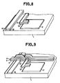
- the metal layer 7, the insulating layer 6, the silicon layer 5, as shown in FIG. 7, are etched so as to obtain LG lines.
- the doped silicon of the columns and connection elements only remains at the intersections with the lines.
- the liquid crystal will then be contained between electrode 2 and a counter electrode not shown and could, for example, be observed in transmission, between crossed polarizers in the case of a nematic type cell in a helix.
- a column CL comprising a metal layer 32 more conductive than ITO makes it possible to avoid the effects of delay lines in large screens.
- a column CL will have an ITO sublayer over a length such as that shown in hatching in FIG. 12.
- each LG line can have an enlargement at each crossing point (transistor). This makes it possible to reduce the parasitic transistor effect which may exist between the drain of the main transistor and the next column.
- the deposits of amorphous silicon layers 5 and of insulating material 6, carried out during the sixth and seventh phases previously described, can be made through a mask preserving the periphery of the substrate 1 from these deposits.
- the peripheral contacts of each LG line is produced directly on the substrate by the metal layer 7 deposited.
- the amorphous silicon the deposition of which is planned for the sixth phase, can be electrically compensated or even weakly p-type in order to reduce the photoconductivity and thus limit the influence of light on the characteristics of the transistors.
Landscapes
- Physics & Mathematics (AREA)
- Nonlinear Science (AREA)
- Engineering & Computer Science (AREA)
- Microelectronics & Electronic Packaging (AREA)
- Mathematical Physics (AREA)
- Chemical & Material Sciences (AREA)
- Crystallography & Structural Chemistry (AREA)
- General Physics & Mathematics (AREA)
- Optics & Photonics (AREA)
- Liquid Crystal (AREA)
- Thin Film Transistor (AREA)
- Non-Volatile Memory (AREA)
Claims (12)
Applications Claiming Priority (2)
| Application Number | Priority Date | Filing Date | Title |
|---|---|---|---|
| FR8512804A FR2586859B1 (fr) | 1985-08-27 | 1985-08-27 | Procede de fabrication d'un transistor de commande pour ecran plat de visualisation et element de commande realise selon ce procede |
| FR8512804 | 1985-08-27 |
Publications (2)
| Publication Number | Publication Date |
|---|---|
| EP0216673A1 EP0216673A1 (de) | 1987-04-01 |
| EP0216673B1 true EP0216673B1 (de) | 1990-07-18 |
Family
ID=9322434
Family Applications (1)
| Application Number | Title | Priority Date | Filing Date |
|---|---|---|---|
| EP86401863A Expired - Lifetime EP0216673B1 (de) | 1985-08-27 | 1986-08-22 | Verfahren zur Herstellung eines Schalttransistors für einen flachen Bildschirm und nach diesem Verfahren hergestelltes Schaltelement |
Country Status (5)
| Country | Link |
|---|---|
| US (1) | US4697331A (de) |
| EP (1) | EP0216673B1 (de) |
| JP (1) | JPS6252970A (de) |
| DE (1) | DE3672729D1 (de) |
| FR (1) | FR2586859B1 (de) |
Families Citing this family (35)
| Publication number | Priority date | Publication date | Assignee | Title |
|---|---|---|---|---|
| US5123847A (en) * | 1983-05-11 | 1992-06-23 | Holmberg Scott H | Method of manufacturing flat panel backplanes, display transistors |
| FR2593630B1 (fr) * | 1986-01-27 | 1988-03-18 | Maurice Francois | Ecran d'affichage a matrice active a resistance de drain et procedes de fabrication de cet ecran |
| FR2593632B1 (fr) * | 1986-01-27 | 1988-03-18 | Maurice Francois | Ecran d'affichage a matrice active et procedes de realisation de cet ecran |
| DE3714164A1 (de) * | 1986-04-30 | 1987-11-05 | Sharp Kk | Fluessigkristallanzeige |
| JPS62265756A (ja) * | 1986-05-14 | 1987-11-18 | Oki Electric Ind Co Ltd | 薄膜トランジスタマトリクス |
| US4907040A (en) * | 1986-09-17 | 1990-03-06 | Konishiroku Photo Industry Co., Ltd. | Thin film Schottky barrier device |
| US4728175A (en) * | 1986-10-09 | 1988-03-01 | Ovonic Imaging Systems, Inc. | Liquid crystal display having pixels with auxiliary capacitance |
| JPS64930A (en) * | 1987-06-24 | 1989-01-05 | Alps Electric Co Ltd | Liquid crystal element |
| US4778258A (en) * | 1987-10-05 | 1988-10-18 | General Electric Company | Protective tab structure for use in the fabrication of matrix addressed thin film transistor liquid crystal displays |
| US4949141A (en) * | 1988-02-04 | 1990-08-14 | Amoco Corporation | Vertical gate thin film transistors in liquid crystal array |
| US5013877A (en) * | 1988-02-08 | 1991-05-07 | Raychem Corporation | Devices for electrical connection |
| JPH0814668B2 (ja) * | 1988-02-16 | 1996-02-14 | シャープ株式会社 | マトリックス型液晶表示パネル |
| US5231039A (en) * | 1988-02-25 | 1993-07-27 | Sharp Kabushiki Kaisha | Method of fabricating a liquid crystal display device |
| JPH01217325A (ja) * | 1988-02-25 | 1989-08-30 | Sharp Corp | 液晶表示装置 |
| EP0333151B1 (de) * | 1988-03-18 | 1993-10-20 | Seiko Epson Corporation | Dünnfilmtransistor |
| JP2678024B2 (ja) * | 1988-08-18 | 1997-11-17 | 松下電器産業株式会社 | 画像表示装置半導体装置及びその製造方法 |
| US4965646A (en) * | 1988-10-21 | 1990-10-23 | General Electric Company | Thin film transistor and crossover structure for liquid crystal displays |
| US4951113A (en) * | 1988-11-07 | 1990-08-21 | Xerox Corporation | Simultaneously deposited thin film CMOS TFTs and their method of fabrication |
| JP2757207B2 (ja) * | 1989-05-24 | 1998-05-25 | 株式会社リコー | 液晶表示装置 |
| US5165165A (en) * | 1989-06-02 | 1992-11-24 | Canon Kabushiki Kaisha | Part inserting apparatus and method for use |
| JP2508851B2 (ja) * | 1989-08-23 | 1996-06-19 | 日本電気株式会社 | 液晶表示素子用アクティブマトリクス基板とその製造方法 |
| US5153142A (en) * | 1990-09-04 | 1992-10-06 | Industrial Technology Research Institute | Method for fabricating an indium tin oxide electrode for a thin film transistor |
| KR960002202B1 (ko) * | 1991-02-04 | 1996-02-13 | 가부시끼가이샤 한도다이 에네르기 겐뀨쇼 | 액정 전기 광학 장치 제작 방법 |
| JP3172841B2 (ja) * | 1992-02-19 | 2001-06-04 | 株式会社日立製作所 | 薄膜トランジスタとその製造方法及び液晶表示装置 |
| US5414283A (en) * | 1993-11-19 | 1995-05-09 | Ois Optical Imaging Systems, Inc. | TFT with reduced parasitic capacitance |
| FR2714766B1 (fr) * | 1993-12-30 | 1996-02-02 | France Telecom | Procédé de fabrication d'un écran d'affichage à matrice active. |
| FR2714765B1 (fr) * | 1993-12-30 | 1996-02-02 | France Telecom | Procédé de réalisation d'une connexion électrique entre deux couches conductrices. |
| FR2718885B1 (fr) * | 1994-04-15 | 1996-07-05 | Thomson Lcd | Procédé de fabrication d'un TFT étagé inverse. |
| FR2718876B1 (fr) * | 1994-04-15 | 1998-03-27 | Thomson Lcd | Procédé de fabrication d'un TFT étagé inverse. |
| US5523604A (en) * | 1994-05-13 | 1996-06-04 | International Rectifier Corporation | Amorphous silicon layer for top surface of semiconductor device |
| FR2737342B1 (fr) * | 1995-07-25 | 1997-08-22 | Thomson Csf | Composant semiconducteur avec dissipateur thermique integre |
| US6069370A (en) * | 1997-03-26 | 2000-05-30 | Nec Corporation | Field-effect transistor and fabrication method thereof and image display apparatus |
| JP2842426B2 (ja) * | 1997-01-28 | 1999-01-06 | 日本電気株式会社 | アクティブマトリクス型液晶表示装置およびその製造方法 |
| US7238557B2 (en) * | 2001-11-14 | 2007-07-03 | Semiconductor Energy Laboratory Co., Ltd. | Semiconductor device and method of fabricating the same |
| TW560001B (en) * | 2002-10-22 | 2003-11-01 | Toppoly Optoelectronics Corp | Method of forming reflective liquid crystal display and driving circuit |
Family Cites Families (15)
| Publication number | Priority date | Publication date | Assignee | Title |
|---|---|---|---|---|
| JPS54154289A (en) * | 1978-05-26 | 1979-12-05 | Matsushita Electric Ind Co Ltd | Manufacture of thin-film transistor array |
| US4413883A (en) * | 1979-05-31 | 1983-11-08 | Northern Telecom Limited | Displays controlled by MIM switches of small capacitance |
| JPS56107287A (en) * | 1980-01-31 | 1981-08-26 | Tokyo Shibaura Electric Co | Image display unit |
| GB2081018B (en) * | 1980-07-31 | 1985-06-26 | Suwa Seikosha Kk | Active matrix assembly for display device |
| US4517733A (en) * | 1981-01-06 | 1985-05-21 | Fuji Xerox Co., Ltd. | Process for fabricating thin film image pick-up element |
| FR2505070B1 (fr) * | 1981-01-16 | 1986-04-04 | Suwa Seikosha Kk | Dispositif non lineaire pour un panneau d'affichage a cristaux liquides et procede de fabrication d'un tel panneau d'affichage |
| JPH0620122B2 (ja) * | 1982-01-19 | 1994-03-16 | キヤノン株式会社 | 半導体素子 |
| US4398340A (en) * | 1982-04-26 | 1983-08-16 | The United States Of America As Represented By The Secretary Of The Army | Method for making thin film field effect transistors |
| FR2533072B1 (fr) * | 1982-09-14 | 1986-07-18 | Coissard Pierre | Procede de fabrication de circuits electroniques a base de transistors en couches minces et de condensateurs |
| JPS59123884A (ja) * | 1982-12-29 | 1984-07-17 | シャープ株式会社 | 液晶表示装置の駆動方法 |
| JPS59204274A (ja) * | 1983-05-06 | 1984-11-19 | Seiko Instr & Electronics Ltd | 薄膜トランジスタ |
| US4633284A (en) * | 1983-11-08 | 1986-12-30 | Energy Conversion Devices, Inc. | Thin film transistor having an annealed gate oxide and method of making same |
| US4543320A (en) * | 1983-11-08 | 1985-09-24 | Energy Conversion Devices, Inc. | Method of making a high performance, small area thin film transistor |
| US4547789A (en) * | 1983-11-08 | 1985-10-15 | Energy Conversion Devices, Inc. | High current thin film transistor |
| US4639087A (en) * | 1984-08-08 | 1987-01-27 | Energy Conversion Devices, Inc. | Displays having pixels with two portions and capacitors |
-
1985
- 1985-08-27 FR FR8512804A patent/FR2586859B1/fr not_active Expired
-
1986
- 1986-08-22 EP EP86401863A patent/EP0216673B1/de not_active Expired - Lifetime
- 1986-08-22 DE DE8686401863T patent/DE3672729D1/de not_active Expired - Fee Related
- 1986-08-25 US US06/900,079 patent/US4697331A/en not_active Expired - Fee Related
- 1986-08-27 JP JP61201173A patent/JPS6252970A/ja active Pending
Also Published As
| Publication number | Publication date |
|---|---|
| FR2586859B1 (fr) | 1987-11-20 |
| US4697331A (en) | 1987-10-06 |
| FR2586859A1 (fr) | 1987-03-06 |
| EP0216673A1 (de) | 1987-04-01 |
| DE3672729D1 (de) | 1990-08-23 |
| JPS6252970A (ja) | 1987-03-07 |
Similar Documents
| Publication | Publication Date | Title |
|---|---|---|
| EP0216673A1 (de) | Verfahren zur Herstellung eines Schalttransistors für einen flachen Bildschirm und nach diesem Verfahren hergestelltes Schaltelement | |
| EP0267824B1 (de) | Transistor-gesteuerter elektrooptischer Anzeigeschirm und Verfahren zu seiner Herstellung | |
| EP0198754B1 (de) | Verfahren zur Herstellung von Steuermatrixen mit Dioden für elektrooptische Anzeigeschirmplatte und nach diesem Verfahren hergestellte Schirmplatte | |
| EP0200599B1 (de) | Verfahren zur Herstellung von nichtlinearen Steuerelementen für elektrooptische Anzeigeschirmplatte und eine nach diesem Verfahren hergestellte Schirmplatte | |
| FR2737938A1 (fr) | Dispositif d'affichage a cristaux liquides et un procede de fabrication d'un tel dispositif | |
| EP0202150B1 (de) | Nichtlineares Steuerelement für elektrooptische Anzeigeschirmplatte und Verfahren zu dessen Herstellung | |
| CA1261953A (fr) | Procede de fabrication de circuits electroniques a base de transistors en couches minces et de condensateurs | |
| EP0246945B1 (de) | Elektro-optischer Anzeigeschirm und sein Herstellungsverfahren | |
| EP0506528B1 (de) | Matrix-Ansteuerungsstruktur für Anzeigeschirm | |
| EP0689721A1 (de) | Verfahren zur herstellung von nicht-invertierten gestaffelten duennschichttransistoren | |
| JPH1039297A (ja) | 反射型液晶表示装置及びその製造方法 | |
| EP0564337B1 (de) | Anzeigeschirm mit optischer Maske und Verfahren zur Verwirklichung dieses Schirms | |
| EP0721213B1 (de) | Gitter mit metallischen Abtastzeilen zur Steuerung von Halbleiter-Gitterzeilen | |
| FR2693034A1 (fr) | Transistor à couche mince et son procédé de fabrication. | |
| EP0182484B1 (de) | Flüssigkristallanzeigevorrichtung | |
| JPH04133035A (ja) | 光弁基板用単結晶薄膜半導体装置 | |
| EP0266252B1 (de) | Transistorgesteuerter elektrooptischer Bildschirm und sein Herstellungsverfahren | |
| JPH05341324A (ja) | 金属配線基板及びその製造方法 | |
| US20030164908A1 (en) | Thin film transistor panel | |
| TWI240134B (en) | Thin film transistor liquid crystal display and method of making the same | |
| EP0755572B1 (de) | Flüssigkristall-bildschirm mit aktiver matrix | |
| FR2605443A1 (fr) | Ecran de visualisation electrooptique a transistor de commande et procede de realisation | |
| JPS61193185A (ja) | 表示素子 | |
| JPH11191625A (ja) | 薄膜トランジスタ | |
| FR2691578A1 (fr) | Procédé de fabrication d'un transistor en couches minces à silicium polycristallin et à grille décalée par rapport au drain. |
Legal Events
| Date | Code | Title | Description |
|---|---|---|---|
| PUAI | Public reference made under article 153(3) epc to a published international application that has entered the european phase |
Free format text: ORIGINAL CODE: 0009012 |
|
| AK | Designated contracting states |
Kind code of ref document: A1 Designated state(s): DE GB NL |
|
| 17P | Request for examination filed |
Effective date: 19870821 |
|
| 17Q | First examination report despatched |
Effective date: 19890320 |
|
| RAP3 | Party data changed (applicant data changed or rights of an application transferred) |
Owner name: THOMSON-CSF |
|
| GRAA | (expected) grant |
Free format text: ORIGINAL CODE: 0009210 |
|
| AK | Designated contracting states |
Kind code of ref document: B1 Designated state(s): DE GB NL |
|
| REF | Corresponds to: |
Ref document number: 3672729 Country of ref document: DE Date of ref document: 19900823 |
|
| GBT | Gb: translation of ep patent filed (gb section 77(6)(a)/1977) | ||
| PLBE | No opposition filed within time limit |
Free format text: ORIGINAL CODE: 0009261 |
|
| STAA | Information on the status of an ep patent application or granted ep patent |
Free format text: STATUS: NO OPPOSITION FILED WITHIN TIME LIMIT |
|
| 26N | No opposition filed | ||
| PGFP | Annual fee paid to national office [announced via postgrant information from national office to epo] |
Ref country code: GB Payment date: 19970814 Year of fee payment: 12 |
|
| PGFP | Annual fee paid to national office [announced via postgrant information from national office to epo] |
Ref country code: NL Payment date: 19970826 Year of fee payment: 12 |
|
| PGFP | Annual fee paid to national office [announced via postgrant information from national office to epo] |
Ref country code: DE Payment date: 19971030 Year of fee payment: 12 |
|
| REG | Reference to a national code |
Ref country code: GB Ref legal event code: 746 Effective date: 19971104 |
|
| PG25 | Lapsed in a contracting state [announced via postgrant information from national office to epo] |
Ref country code: GB Free format text: LAPSE BECAUSE OF NON-PAYMENT OF DUE FEES Effective date: 19980822 |
|
| PG25 | Lapsed in a contracting state [announced via postgrant information from national office to epo] |
Ref country code: NL Free format text: LAPSE BECAUSE OF NON-PAYMENT OF DUE FEES Effective date: 19990301 |
|
| GBPC | Gb: european patent ceased through non-payment of renewal fee |
Effective date: 19980822 |
|
| NLV4 | Nl: lapsed or anulled due to non-payment of the annual fee |
Effective date: 19990301 |
|
| PG25 | Lapsed in a contracting state [announced via postgrant information from national office to epo] |
Ref country code: DE Free format text: LAPSE BECAUSE OF NON-PAYMENT OF DUE FEES Effective date: 19990601 |