EP0214701B1 - Aufnahmeeinrichtung für eine Vorratslänge einer optischen Leitung - Google Patents
Aufnahmeeinrichtung für eine Vorratslänge einer optischen Leitung Download PDFInfo
- Publication number
- EP0214701B1 EP0214701B1 EP86201546A EP86201546A EP0214701B1 EP 0214701 B1 EP0214701 B1 EP 0214701B1 EP 86201546 A EP86201546 A EP 86201546A EP 86201546 A EP86201546 A EP 86201546A EP 0214701 B1 EP0214701 B1 EP 0214701B1
- Authority
- EP
- European Patent Office
- Prior art keywords
- storage device
- optical cable
- core
- turns
- storage
- Prior art date
- Legal status (The legal status is an assumption and is not a legal conclusion. Google has not performed a legal analysis and makes no representation as to the accuracy of the status listed.)
- Expired - Lifetime
Links
- 239000013307 optical fiber Substances 0.000 title description 8
- 230000003287 optical effect Effects 0.000 claims description 38
- 230000002093 peripheral effect Effects 0.000 claims description 8
- 239000004020 conductor Substances 0.000 claims description 2
- 238000005253 cladding Methods 0.000 claims 1
- 238000004804 winding Methods 0.000 description 10
- 238000003780 insertion Methods 0.000 description 4
- 230000037431 insertion Effects 0.000 description 4
- 238000005452 bending Methods 0.000 description 3
- 238000010521 absorption reaction Methods 0.000 description 1
- 238000010276 construction Methods 0.000 description 1
- 238000004519 manufacturing process Methods 0.000 description 1
- 238000007493 shaping process Methods 0.000 description 1
Images


Classifications
-
- G—PHYSICS
- G02—OPTICS
- G02B—OPTICAL ELEMENTS, SYSTEMS OR APPARATUS
- G02B6/00—Light guides; Structural details of arrangements comprising light guides and other optical elements, e.g. couplings
- G02B6/44—Mechanical structures for providing tensile strength and external protection for fibres, e.g. optical transmission cables
- G02B6/4439—Auxiliary devices
- G02B6/444—Systems or boxes with surplus lengths
- G02B6/4453—Cassettes
-
- G—PHYSICS
- G02—OPTICS
- G02B—OPTICAL ELEMENTS, SYSTEMS OR APPARATUS
- G02B6/00—Light guides; Structural details of arrangements comprising light guides and other optical elements, e.g. couplings
- G02B6/44—Mechanical structures for providing tensile strength and external protection for fibres, e.g. optical transmission cables
- G02B6/4439—Auxiliary devices
- G02B6/444—Systems or boxes with surplus lengths
- G02B6/4452—Distribution frames
- G02B6/44524—Distribution frames with frame parts or auxiliary devices mounted on the frame and collectively not covering a whole width of the frame or rack
-
- G—PHYSICS
- G02—OPTICS
- G02B—OPTICAL ELEMENTS, SYSTEMS OR APPARATUS
- G02B6/00—Light guides; Structural details of arrangements comprising light guides and other optical elements, e.g. couplings
- G02B6/44—Mechanical structures for providing tensile strength and external protection for fibres, e.g. optical transmission cables
- G02B6/4439—Auxiliary devices
- G02B6/444—Systems or boxes with surplus lengths
- G02B6/44528—Patch-cords; Connector arrangements in the system or in the box
Definitions
- the invention relates to a receptacle with a flat storage space and with a supply length of an optical line which can be pulled out or pushed in as required, the storage space being fixed by a core, by lateral guide walls which are fixedly connected to it and extending orthogonally therefrom, and by the guide walls connected outer peripheral walls is formed, and wherein an outer end of the winding length wound around the core can be pulled out by reducing the diameter of the turns through an opening of the outer peripheral wall.
- the invention has for its object to design the receiving device of the type mentioned in such a way that a jam-free pulling out and pushing back in one end of an optical line, which can optionally be a ribbon cable, is possible with an extremely flat construction.
- the solution is achieved in that the distance between the guide walls is greater than the width of the optical line and less than 1.3 times this width, that the optical line is inserted into the storage space with turns running in a spiral in one plane, and that in the immediate vicinity of the peripheral surface of the core there is an opening leading out of the storage space, through which the inner end of a spirally guided supply length of the optical line is led out of the storage space.
- the diameter of the core should advantageously be greater than 40 mm, in particular greater than 50 mm.
- the change in diameter of the turns caused by pulling out or pushing in one end of the optical line is not impeded by the fixed end of the optical line which is to be led in from outside, if the fixed end of the optical line is from a plane outside the winding plane and radially outside starting obliquely up to at least approximately to the peripheral surface of the core in a guide channel.
- Such a guide channel is advantageously at least partially open to one of the flat sides of the receiving device, so that it can be produced easily and the end of the optical line can be inserted easily.
- a preferred embodiment for inserting a ribbon cable is characterized in that the channel is rectangular in accordance with the cross-sectional dimensions of a ribbon cable and is set so that its wider side is radially outside parallel to the direction of the winding plane and radially inside parallel to the outer surface of the core and this extends adjacent. It is thereby achieved that practically no increase in the receiving device is required for the fixed end, because this runs flat in the space required for the guide wall anyway. In addition, sharp bends are avoided. A subsequent turn is not already in the setting area of the fixed end, but only when it runs in parallel to the outer surface of the core.
- a plurality of receiving devices of the same type according to the invention can be arranged coaxially one above the other and can be connected by means of interlocking, possibly latching, elements.
- the lateral guide walls it is not necessary for the lateral guide walls to be designed as closed flange surfaces.
- the guide walls consist at least on one side of at least 3 radially extending guide spokes, which are separated in the central area by insertion slots.
- the turns of the optical lines can be inserted through the slots. If these run obliquely to the tangent of the turns of the optical line, later accidental sliding out is prevented.
- a further advantageous embodiment is characterized in that it has a central winding part which can be detachably inserted into an outer part which forms the outer peripheral walls and radially outer partial sections of the lateral guide walls.
- receiving devices are each shown for receiving flat band-shaped optical lines 1 to 5.
- Such ribbon cables consist of several individual optical fibers connected flat next to each other.
- the free height between the lateral guide walls, namely the closed rear walls 6 to 10 on the one hand and the front walls consisting of radial spokes 11 to 16 on the other hand, is then to be selected slightly larger than the width of the ribbon cables measured in the flat plane. It should not exceed 1.3 times this width, so that a smooth and orderly spiral guide is ensured.
- the free height is slightly more than the diameter of the wires or lines.
- the diameter of the cores 17 to 21 is 50 mm. In the case of direct contact with the core, the minimum bending radii of the innermost turn are certainly larger than the minimum permissible value for optical fibers.
- the diameter D of the outer guide walls 22 to 26 is preferably 1.8 to 2.2 times the core diameter d. With this ratio, there is good absorption capacity with relatively small external dimensions.
- the outer guide walls do not necessarily have to be cylindrical, they can also be made of there are planar elements abutting one another at an angle, on which the outermost turn lies point by point.
- the optical ribbon cable 1 In the embodiment shown in FIGS. 1 and 2, only 3 turns of the optical ribbon cable 1 are drawn for the sake of better illustration, which can be threaded through the insertion slots 27, which, as in the other figures, run obliquely to the tangential direction of the turns, so that an unintentional Slipping out of the inserted turns is prevented.
- the receiving device consists of detachably interlocked parts, the winding part 28 and the outer part 29, the windings can also be wound around the core 17 of the winding part 28 in a simple manner before the two parts are joined together.
- the part of the ribbon cable 1 leading to the inner turn is freely guided between the contact on the circumference of the core 17 and the radially outer holder 30.
- FIGS. 3 and 4 an embodiment according to FIGS. 3 and 4 is recommended. This is drawn in one piece, but can of course be composed of several individual parts.
- the ribbon cable 2 is introduced through the oblique slots 31 of the spoke-like guide walls 12.
- the fixed end 32 of the ribbon cable 2 is guided in an insertion channel to the exit point 33. It initially runs flat through a downwardly open channel 34 of the guide wall 7 and enters the receiving space between the guide walls 7 and 12 in the vicinity of the peripheral surface of the core 18.
- a typical area of application for receiving devices according to the invention is a connecting sleeve according to FIG. 5, of which only one housing plate 36 is designated.
- the reserve length of the first ribbon cable 3 is accommodated in the receiving device 37, that of the ribbon cable 4 in the similar recording device 38.
- the stored reserve lengths can first be pulled out and pushed back into the receiving device after the splices have been completed.
- FIG. 7 in the event that instead of a ribbon cable 4 fewer optical fibers containing and accordingly narrower ribbon cables are fed, two stacked receiving devices are shown, each with receiving spaces adapted to the narrower widths of the individual ribbon cables.
- FIG. 8 shows an end termination for a ribbon cable 5.
- the reserve lengths required for making the connections of the individual optical fibers 40 with plug-in elements 41 are stored in the receiving device 43.
Landscapes
- Physics & Mathematics (AREA)
- General Physics & Mathematics (AREA)
- Optics & Photonics (AREA)
- Light Guides In General And Applications Therefor (AREA)
- Mechanical Coupling Of Light Guides (AREA)
- Storage Of Web-Like Or Filamentary Materials (AREA)
- Storing, Repeated Paying-Out, And Re-Storing Of Elongated Articles (AREA)
Description
- Die Erfindung bezieht sich auf eine Aufnahmeeinrichtung mit einem flachen Speicherraum und mit einer nach Bedarf herausziehbaren oder hineinschiebbaren Vorratslänge einer optischen Leitung, wobei der Speicherraum durch einem Kern, durch mit diesem fest verbundene und sich von diesem orthogonal erstreckende seitliche Führungswandungen sowie durch mit den Führungswandungen fest verbundene äußere Umfangswandungen gebildet ist, und wobei ein äußeres Ende der um den Kern gewundenen Vorratslänge unter Verkleinerung der Windungsdurchmesser durch eine Öffnung der äußeren Umfangswandung herausziehbar ist.
- Eine derartige Anordnung ist durch die DE-A-32 48 003 und auch durch die DE-A-27 21 300 bekannt. Dabei werden Lichtwellenleiter in mehrere Windungen aufweisende Schlaufen gelegt. Beim Herausziehen eines Endes besteht die Gefahr der Verklemmung der Windungen untereinander, so daß ein Wiederhineinschieben nicht mehr möglich ist. Die Ablage von Bandleitungen, welche aus mehreren fest aneinander verbundenen Lichtwellenleitern bestehen, würde darüberhinaus entsprechend der Anzahl der nebeneinander zu verlegenden Windungen hohe Ablagebehälter bedingen.
- Der Erfindung liegt die Aufgabe zugrunde, die Aufnahmeeinrichtung der eingangs genannten Art so zu gestalten, daß bei äußerst flachem Aufbau ein klemmfreies Herausziehen und Wiederhineinschieben eines Endes einer optischen Leitung, welche gegebenenfalls eine Bandleitung sein kann, möglich ist.
- Die Lösung gelingt dadurch, daß der Abstand zwischen den Führungswandungen größer als die Breite der optischen Leitung und kleiner als das 1,3- fache dieser Breite ist, daß die optische Leitung mit spiralförmig in einer Ebene verlaufenden Windungen in den Speicherraum eingelegt ist, und daß in unmittelbarer Nähe der Umfangsfläche des Kerns eine aus dem Speicherraum führende Öffnung vorgesehen ist, durch welche das innere Ende einer spiralig geführten Vorratslänge der optischen Leitung aus dem Speicherraum herausgeführt ist.
- Durch die spiralförmige Verlegung der Windungen radial übereinander in einer Ebene ergeben sich extrem flache Behälter. Dabei werden die Windungen definiert geordnet geführt. Das Herausziehen oder Wiederhineinschieben eines Endes ist leichtgängig möglich und eine Verklemmung ist ausgeschlossen, wenn das herausziehbare Ende von der radial außen liegenden Windung gebildet ist. Deshalb kann eine Vielzahl von Windungen problemlos eingewickelt sein. Selbst bei kleiner radialer Abmessungen der erfindungsgemäßen Aufnahmeeinrichtung sind darin große Vorratslängen unterbringbar.
- Damit auch bei vollständigem festen Ausziehen eines Endes der optischen Leitung der zulässige Mindestbiegeradius nicht unterschritten wird, ist der Durchmesser des Kerns vorteilhaft größer als 40 mm, insbesondere größer als 50 mm zu wählen.
- Eine optimale Ausnutzung des Speicherraums ergibt sich, wenn die Anzahl n der Windungen
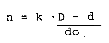
beträgt mit - d =
- Durchmesser des Kerns,
- D =
- maximaler Durchmesser der äußersten Windung
- do=
- Breite der optischen Leitung
0,2<k<0,3, insbesondere k = 0,25. - Die beim Herausziehen oder Hineinschieben eines Endes der optischen Leitung bewirkte Durchmesseränderung der Windungen wird durch das von außen nach innen zu führende, fest verlegte Ende der optischen Leitung nicht behindert, wenn das fest verlegte Ende der optischen Leitung von einer Ebene außerhalb der Windungsebene und radial außen beginnend schräg bis zumindest annähernd zur Umfangsfläche des Kerns hin in einem Führungskanal verläuft.
- Ein solcher Führungskanal ist vorteilhaft zumindest teilweise zu einer der Flachseiten der Aufnahmeeinrichtung hin geöffnet, damit er einfach herstellbar und das Ende der optischen Leitung leicht einlegbar ist.
- Eine bevorzugte Ausführungsform zum Einlegen einer Bandleitung ist dadurch gekennzeichnet, daß der Kanal rechteckig entsprechend den Querschnittsabmessungen einer Bandleitung gestaltet ist und in der Weise geschränkt verläuft, daß sich seine breitere Seite radial außen parallel zur Richtung der Windungsebene und radial innen parallel zur Mantelfläche des Kerns und dieser benachbart erstreckt. Dadurch wird erreicht, daß für das fest verlegte Ende praktisch keine Erhöhung der Aufnahmeeinrichtung erforderlich ist, weil dieses flach im ohnehin für die Führungswandung erforderlichen Raum verläuft. Darüberhinaus sind scharfe Krümmungen vermieden. Eine folgende Windung liegt nicht bereits im Schränkungsbereich des festverlegten Endes an diesem an, sondern erst dann, wenn es in parelleler Führung zur Mantelfläche des Kerns verläuft.
- Zur Bildung eines Stapels können mehrere gleichartige erfindungsgemäße Aufnahmeeinrichtungen koaxial übereinander angeordnet werden und dabei mittels formschlüssig, gegebenenfalls rastend ineinandergreifender Elemente verbunden sein.
- Es ist nicht erforderlich, daß die seitlichen Führungswandungen als geschlossene Flanschflächen ausgebildet sind. Eine bevorzugte Ausführungsart ist dadurch gekennzeichnet, daß die Führungswandungen zumindest einseitig aus mindestens 3 sich radial erstreckenden Führungsspeichen bestehen, welche im mittleren Bereich durch Einführungsschlitze getrennt sind. Die Windungen der optischen Leitungen können durch die Schlitze eingebracht werden. Wenn diese schräg zur Tangente der Windungen der optischen Leitung verlaufen, ist ein späteres zufälliges Herausgleiten verhindert.
- Eine weitere vorteilhafte Ausführungsform ist dadurch gekennzeichnet, daß sie einen zentralen Aufwickelteil aufweist, welcher lösbar in einen Außenteil einfügbar ist, welcher die äußeren Umfangswandungen und radial äußeren Teilabschnitte der seitlichen Führungswandungen bildet.
- Die Erfindung wird anhand der Beschreibung von in der Zeichnung dargestellten Ausführungsbeispielen näher erläutert.
- Figur 1
- zeigt eine zweiteilige Aufnahmeeinrichtung gemäß der Erfindung zur Ablage mehrerer Windungen einer bandförmigen optischen Leitung
- Figur 2
- zeigt einen Querschnitt entsprechend der Linie A-B durch die Ausführung nach Figur 1
- Figur 3
- zeigt eine einstöckige Ausführungart ähnlich Figur 1, jedoch mit einem Einführungskanal für das fest verlegte Ende der optischen Leitung
- Figur 4
- zeigt einen Querschnitt entsprechend der Linie C-D nach Figur 3
- Figur 5
- zeigt ein typisches Anwendungsbeispiel für erfindungsgemäße Aufnahmeeinrichtungen
- Figur 6
- zeigt einen Querschnitt durch die Anordnung nach Figur 5
- Figur 7
- zeigt einen Querschnitt durch zwei übereinander gestapelte Aufnahmeeinrichtungen
- Figur 8
- zeigt ein weiteres Anwendungsbeispiel für den Einsatz einer erfindungsgemäßen Aufnahmeeinrichtung.
- In den Ausführungsbeispielen sind erfindungsgemäße Aufnahmeeinrichtungen jeweils für die Aufnahme flacher bandförmiger optischer Leitungen 1 bis 5 dargestellt. Derartige Bandleitungen bestehen aus mehreren flach nebeneinander verbundenen einzelnen Lichtwellenleitern. Die freie Höhe zwischen den seitlichen Führungswandungen, nämlich den geschlossenen Rückwandungen 6 bis 10 einerseits und den aus radialen Speichen 11 bis 16 bestehenden Vorderwandungen andererseits, ist dann geringfügig größer die in der Flachebene gemessene Breite der Bandleitungen zu wählen. Sie sollte das 1,3 fache dieser Breite nicht überschreiten, damit eine gut gleitfähige und geordnete Spiralführung gewährleitet ist.
- Wenn die erfindungsgemäße Aufnahmeeinrichtung jedoch zur Ablage von Rundadern oder einzelnen Lichtwellenleitern dienen soll, beträgt die freie Höhe geringfügig mehr als der Durchmesser der Adern bzw. Leitungen.
- Der Durchmesser der Kerne 17 bis 21 beträgt 50 mm. Die minimalen Biegeradien der innersten Windung sind im Falle der direkten Anlage am Kern mit Sicherheit größer als der für Lichtwellenleiter minimal zulässige Wert.
- Der Durchmesser D der äußeren Führungswandungen 22 bis 26 beträgt vorzugsweise das 1,8 bis 2,2 fache des Kerndurchmessers d. Bei diesem Verhältnis ergibt sich eine gute Aufnahmefähigkeit bei relativ geringen Außenabmessungen. Die äußeren Führungswandungen brauchen nicht unbedingt zylindrisch zu verlaufen, sondern sie können auch aus winklig aneinanderstoßenden ebenen Elementen bestehen, an welchen die äußerste Windung punktweise anliegt.
- Bei gegebenen Werten für D und d sowie für den Durchmesser d o einer Rundader oder eines Lichtwellenleiters bzw. der Dicke einer Bandleitung (kleinere Querschnittsseite) ergibt sich eine maximal ausziehfähige Länge, wenn die Anzahl n der Windungen etwa
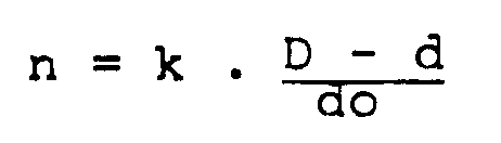
mit k = 0,25 gewählt wird. Werte von 0,2 < k < 0,3 führen jedoch auch zu praktisch brauchbaren Ergebnissen. - Bei der in den Figuren 1 und 2 dagestellten Ausführungform sind der besseren Darstellbarkeit wegen nur 3 Windungen der optischen Bandleitung 1 gezeichnet, welche durch die Einführungsschlitze 27 eingefädelt werden können, welche ebenso wie in den weiteren Figuren schräg zur Tangentialrichtung der Windungen verlaufen, damit ein unbeabsichtigtes Wiederhinausgleiten der eingelegten Windungen verhindert ist. Wenn jedoch wie im Ausführungsbeispiel die Aufnahmeeinrichtung aus lösbar ineinandergefügten Teilen, dem Aufwickelteil 28 und dem Außenteil 29 besteht, können die Windungen auch vor dem Zusammenfügen beider Teile in einfacher Weise um den Kern 17 des Aufwickelteils 28 gewickelt werden. Der zur inneren Windung führende festliegende Teil der Bandleitung 1 ist zwischen der Anlage am Umfang des Kerns 17 und der radial außen liegenden Halterung 30 frei geführt. In diesem Bereich tordiert die Querschnittsebene der Bandleitung 1 um 90o von einer flach zur Ebene der Führungswandungen gerichteten Lage in eine zur Umfangsfläche 17 parallele Lage. Dabei kann nicht ganz ausgeschlossen werden, daß der frei über die Windungen geführte Abschnitt der Bandleitung 1 an den darunterliegenden Windungen anliegt und deren Gleiten behindert. Wenn wie in den Ausführungsbeispielen radiale Speichen 11 als Führungswandungen dienen, zwischen welchen große Bereiche offen bleiben, so daß die Windungen zugänglich sind, können eventuelle Verklemmungen leicht gelöst werden.
- Insbesondere, wenn mehrere der erfindungsgemäßen Aufnahmeeinrichtungen gemäß Figur 7 aufeinander gestapelt werden sollen, empfiehlt sich eine Ausführungsart nach den Figuren 3 und 4. Diese ist einstückig gezeichnet, kann jedoch selbstverständlich aus mehreren Einzelteilen zusammengesetzt sein. Die Bandleitung 2 ist durch die schräg verlaufenden Schlitze 31 der speichenartigen Führungswandungen 12 eingebracht. Im Gegensatz zur prinzipiell ähnlichen Ausführungsform nach den Figuren 1 und 2 ist das festliegende Ende 32 der Bandleitung 2 in einem Einführungskanal bis zur Austrittsstelle 33 geführt. Es verläuft zunächst flach durch eine nach unten offene Rinne 34 der Führungswandung 7 und tritt in der Nähe der Umfangsfläche des Kerns 18 in den Aufnahmeraum zwischen den Führungswandungen 7 und 12 ein. Es verläuft danach, sich stetig bis zum Winkel von 90o an der Stelle 33 drehend, durch eine zur Seite der Wandungen 12 hin offenen Rinne 35 im Kern 18. Deshalb kann das Ende 32 die Spiralwindungen nicht behindern, da es durch Wandungen des aus den Rinnen 34 und 35 bestehenden Einführungskanals gegen eine Berührung mit den folgenden Windungen abgeschirmt ist. Bei der Formgebung der Rinne 35 ist darauf zu achten, daß an keiner Stelle der minimal zulässigen Biegeradius der Lichtwellenleiter unterschritten wird. Der Schränkungsverlauf ist in vorbestimmter Weise festgelegt.
- Ein typisches Anwendungsgebiet für erfindungsgemäße Aufnahmeeinrichtungen ist eine Verbindungsmuffe nach Figur 5, von welcher nur eine Gehäuseplatte 36 bezeichnet ist. Die Reservelänge der ersten Bandleitung 3 ist in der Aufnahmeeinrichtung 37, die der Bandleitung 4 in der gleichartigen Aufnahmeeinrichtung 38 untergebracht. Zum bequemen Herstellen der Spleiße 39 können zunächst die gespeicherten Reservelängen herausgezogen und nach der Fertigstellung der Spleiße wieder in die Aufnahmevorrichtung zurückgeschoben werden.
- In Figur 7 sind für den Fall, daß statt einer Bandleitung 4 weniger Lichtwellenleiter enthaltende und dementsprechend schmälere Bandleitungen zugeführt werden, zwei übereinandergestapelte Aufnahmeeinrichtungen mit jeweils den schmäleren Breiten der einzelnen Bandleitungen angepaßten Aufnahmeräumen dargestellt.
- Figur 8 zeigt einen Endabschluß für eine Bandleitung 5. Die zur Herstellung der Anschlüsse der einzelnen Lichtwellenleiter 40 mit Steckelementen 41 erforderlichen Reservelängen sind in der Aufnahmeeinrichtung 43 gespeichert.
Claims (15)
- Aufnahmeeinrichtung mit einem flachen Speicherraum und mit einer nach Bedarf herausziehbaren oder hineinschiebbaren Vorratslänge einer optischen Leitung (1 bis 5), wobei der Speicherraum durch einem Kern (17 bis 21), durch mit diesem fest verbundene und sich von diesem orthogonal erstreckende seitliche Führungswandungen (6 bis 10 bzw. 11 bis 16) sowie durch eine fest mit den Führungswandungen verbundene äußere Umfangswandung (22 bis 26) gebildet ist, und wobei ein äußeres Ende der um den Kern gewundenen Vorratslänge (1 bis 5) unter Verkleinerung der Windungsdurchmesser durch eine Öffnung der äußeren Umfangswandung (22 bis 26) herausziehbar ist,
dadurch gekennzeichnet, daß der Abstand zwischen den Führungswandungen (6 bis 10 bzw. 11 bis 16) größer als die Breite der optischen Leitung (1 bis 5) und kleiner als das 1,3-fache dieser Breite ist, daß die optische Leitung (1 bis 5) mit spiralförmig in einer Ebene verlaufenden Windungen in den Speicherraum eingelegt ist, und daß in unmittelbarer Nähe der Umfangsfläche des Kerns (17 bis 21) eine aus dem Speicherraum führende Öffnung (33) vorgesehen ist, durch welche das innere Ende (32) einer spiralig geführten Vorratslänge der optischen Leitung aus dem Speicherraum herausgeführt ist. - Aufnahmeeinrichtung nach Anspruch 1,
dadurch gekennzeichnet, daß Mittel (34,35) zur Verlegung des inneren Endes (32) der optischen Leitung (2) vorgesehen sind, welche einen außerhalb des Speicherraums verlaufenden Einführungskanal bilden. - Aufnahmeeinrichtung nach Anspruch 1 oder 2,
dadurch gekennzeichnet, daß der Durchmesser d des Kerns (17 bis 21) größer als 40 mm ist. - Aufnahmeeinrichtung nach einem der Ansprüche 1 bis 3,
dadurch gekennzeichnet, daß die Anzahl n Windungen d = Durchmesser des KernsD = maximaler Durchmesser der äußersten Windungdo= Breite der optischen Leitung
0,2<k<0,3, insbesondere k = 0,25. - Aufnahmeeinrichtung nach einem der Ansprüche 1 bis 4,
dadurch gekennzeichnet, daß die optische Leitung (1 bis 5) eine Rundader oder ein Lichtwellenleiter ist. - Aufnahmeeinrichtung nach einem der Ansprüche 1 bis 5,
dadurch gekennzeichnet, daß die optische Leitung eine Bandleitung (1 bis 5) mit festverbunden nebeneinander angeordneten Lichtwellenleitern oder Rundadern besteht. - Aufnahmeeinrichtung nach einem der Ansprüche 1 bis 6,
dadurch gekennzeichnet, daß ein Führungskanal (Rinne 34,35) für das festverlegte innere Ende (32) der optischen Leitung vorgesehen ist, welcher von einer Ebene außerhalb der Windungsebene und radial außen beginnend schräg bis zumindest annähernd zur Umfangsfläche des Kerns hin verläuft. - Aufnahmeeinrichtung nach Anspruch 7,
dadurch gekennzeichnet, daß der Führungskanal (Rinnen 34, 35) zumindest teilweise zu einer der Flachseiten der Aufnahmeeinrichtung hin geöffnet ist. - Aufnahmeeinrichtung nach Anspruch 7 oder 8,
dadurch gekennzeichnet, daß der Kanal rechteckig entsprechend den Querschnittsabmessungen einer Bandleitung (2) gestaltet ist und in der Weise geschränkt verläuft, daß sich seine breitere Seite radial außen parallel zur Richtung der Windungsebene und radial innen (Stelle 33) parallel zur Mantelfläche des Kerns (18) und dieser benachbart erstreckt. - Aufnahmeeinrichtung nach einem der Ansprüche 1 bis 9,
dadurch gekennzeichnet, daß die Leiter des herausziehbaren Endes der optischen Leitung (5) mit Steckerelementen (41) verbunden sind. - Aufnahmeeinrichtung nach einem der Ansprüche 1 bis 10,
dadurch gekennzeichnet, daß die Führungswandungen zumindest einseitig aus mindestens drei sich radial erstreckenden Führungsspeichen (11 bis 16) bestehen, welche im mittleren Bereich durch Einführungsschlitze (27,31) getrennt sind. - Aufnahmeeinrichtung nach Anspruch 11,
dadurch gekennzeichnet, daß die Einführungsschlitze (27,31) schräg zur Tangente der Windungen der optischen Leitung (1 bis 5) verlaufen. - Stapel von gleichartigen Aufnahmeeinrichtungen mit im Speicherraum angeordneten optischen Leitungen,
dadurch gekennzeichnet, daß die Aufnahmeeinrichtungen nach einem der Ansprüche 1 bis 12 ausgebildet sind. - Stapel von gleichartigen Aufnahmeeinrichtungen nach Anspruch 13,
dadurch gekennzeichnet, daß die Aufnahmeeinrichtungen mittels formschlüssig und gegebenenfalls rastend ineinandergreifener Elemente miteinander verbunden sind. - Endabschlußgehäuse für eine optische Bandleitung (5), welche optische Steckerelemente (41) aufweist, mit denen die einzelnen Lichtwellenleiter (40) der Bandleitung (5) verbunden sind,
dadurch gekennzeichnet, daß mit dem Endabschlußgehäuse (Fig. 8) eine Aufnahmeeinrichtung nach einem der Ansprüche 1 bis 12 verbunden ist, in deren Speicherraum eine Vorratslänge der optischen Bandleitung (5) eingelegt ist.
Applications Claiming Priority (2)
| Application Number | Priority Date | Filing Date | Title |
|---|---|---|---|
| DE19853532314 DE3532314A1 (de) | 1985-09-11 | 1985-09-11 | Aufnahmeeinrichtung fuer eine vorratslaenge einer optischen leitung |
| DE3532314 | 1985-09-11 |
Publications (3)
| Publication Number | Publication Date |
|---|---|
| EP0214701A2 EP0214701A2 (de) | 1987-03-18 |
| EP0214701A3 EP0214701A3 (en) | 1987-10-21 |
| EP0214701B1 true EP0214701B1 (de) | 1992-03-04 |
Family
ID=6280600
Family Applications (1)
| Application Number | Title | Priority Date | Filing Date |
|---|---|---|---|
| EP86201546A Expired - Lifetime EP0214701B1 (de) | 1985-09-11 | 1986-09-09 | Aufnahmeeinrichtung für eine Vorratslänge einer optischen Leitung |
Country Status (4)
| Country | Link |
|---|---|
| US (1) | US4765708A (de) |
| EP (1) | EP0214701B1 (de) |
| JP (1) | JP2593851B2 (de) |
| DE (2) | DE3532314A1 (de) |
Cited By (33)
| Publication number | Priority date | Publication date | Assignee | Title |
|---|---|---|---|---|
| US7926975B2 (en) | 2007-12-21 | 2011-04-19 | Altair Engineering, Inc. | Light distribution using a light emitting diode assembly |
| US7938562B2 (en) | 2008-10-24 | 2011-05-10 | Altair Engineering, Inc. | Lighting including integral communication apparatus |
| US7946729B2 (en) | 2008-07-31 | 2011-05-24 | Altair Engineering, Inc. | Fluorescent tube replacement having longitudinally oriented LEDs |
| US7976196B2 (en) | 2008-07-09 | 2011-07-12 | Altair Engineering, Inc. | Method of forming LED-based light and resulting LED-based light |
| US8118447B2 (en) | 2007-12-20 | 2012-02-21 | Altair Engineering, Inc. | LED lighting apparatus with swivel connection |
| US8214084B2 (en) | 2008-10-24 | 2012-07-03 | Ilumisys, Inc. | Integration of LED lighting with building controls |
| US8256924B2 (en) | 2008-09-15 | 2012-09-04 | Ilumisys, Inc. | LED-based light having rapidly oscillating LEDs |
| US8299695B2 (en) | 2009-06-02 | 2012-10-30 | Ilumisys, Inc. | Screw-in LED bulb comprising a base having outwardly projecting nodes |
| US8324817B2 (en) | 2008-10-24 | 2012-12-04 | Ilumisys, Inc. | Light and light sensor |
| US8330381B2 (en) | 2009-05-14 | 2012-12-11 | Ilumisys, Inc. | Electronic circuit for DC conversion of fluorescent lighting ballast |
| US8360599B2 (en) | 2008-05-23 | 2013-01-29 | Ilumisys, Inc. | Electric shock resistant L.E.D. based light |
| US8362710B2 (en) | 2009-01-21 | 2013-01-29 | Ilumisys, Inc. | Direct AC-to-DC converter for passive component minimization and universal operation of LED arrays |
| US8421366B2 (en) | 2009-06-23 | 2013-04-16 | Ilumisys, Inc. | Illumination device including LEDs and a switching power control system |
| US8444292B2 (en) | 2008-10-24 | 2013-05-21 | Ilumisys, Inc. | End cap substitute for LED-based tube replacement light |
| US8454193B2 (en) | 2010-07-08 | 2013-06-04 | Ilumisys, Inc. | Independent modules for LED fluorescent light tube replacement |
| US8540401B2 (en) | 2010-03-26 | 2013-09-24 | Ilumisys, Inc. | LED bulb with internal heat dissipating structures |
| US8541958B2 (en) | 2010-03-26 | 2013-09-24 | Ilumisys, Inc. | LED light with thermoelectric generator |
| US8556452B2 (en) | 2009-01-15 | 2013-10-15 | Ilumisys, Inc. | LED lens |
| US8653984B2 (en) | 2008-10-24 | 2014-02-18 | Ilumisys, Inc. | Integration of LED lighting control with emergency notification systems |
| US8664880B2 (en) | 2009-01-21 | 2014-03-04 | Ilumisys, Inc. | Ballast/line detection circuit for fluorescent replacement lamps |
| US8674626B2 (en) | 2008-09-02 | 2014-03-18 | Ilumisys, Inc. | LED lamp failure alerting system |
| US8894430B2 (en) | 2010-10-29 | 2014-11-25 | Ilumisys, Inc. | Mechanisms for reducing risk of shock during installation of light tube |
| US8901823B2 (en) | 2008-10-24 | 2014-12-02 | Ilumisys, Inc. | Light and light sensor |
| US9057493B2 (en) | 2010-03-26 | 2015-06-16 | Ilumisys, Inc. | LED light tube with dual sided light distribution |
| US9072171B2 (en) | 2011-08-24 | 2015-06-30 | Ilumisys, Inc. | Circuit board mount for LED light |
| US9163794B2 (en) | 2012-07-06 | 2015-10-20 | Ilumisys, Inc. | Power supply assembly for LED-based light tube |
| US9184518B2 (en) | 2012-03-02 | 2015-11-10 | Ilumisys, Inc. | Electrical connector header for an LED-based light |
| US9267650B2 (en) | 2013-10-09 | 2016-02-23 | Ilumisys, Inc. | Lens for an LED-based light |
| US9271367B2 (en) | 2012-07-09 | 2016-02-23 | Ilumisys, Inc. | System and method for controlling operation of an LED-based light |
| US9285084B2 (en) | 2013-03-14 | 2016-03-15 | Ilumisys, Inc. | Diffusers for LED-based lights |
| US9510400B2 (en) | 2014-05-13 | 2016-11-29 | Ilumisys, Inc. | User input systems for an LED-based light |
| US9574717B2 (en) | 2014-01-22 | 2017-02-21 | Ilumisys, Inc. | LED-based light with addressed LEDs |
| US10161568B2 (en) | 2015-06-01 | 2018-12-25 | Ilumisys, Inc. | LED-based light with canted outer walls |
Families Citing this family (35)
| Publication number | Priority date | Publication date | Assignee | Title |
|---|---|---|---|---|
| DE3532312A1 (de) * | 1985-09-11 | 1987-03-12 | Philips Patentverwaltung | Verfahren zur herstellung einer verbindung zwischen zwei optischen leitungen und anordnung zur ausuebung des verfahrens |
| DE3706768A1 (de) * | 1987-03-03 | 1988-09-15 | Philips Patentverwaltung | Aufnahmevorrichtung fuer die vorratslaenge mindestens eines lichtwellenleiters |
| US4874904A (en) * | 1988-04-14 | 1989-10-17 | Brintec Corporation | Fiber optic faceplate assembly |
| DE3841607C2 (de) * | 1988-12-08 | 1996-05-23 | Siemens Ag | Kassette für Überlängen von Lichtwellenleitern im Spleißstellenbereich |
| DE3841605C2 (de) * | 1988-12-08 | 1996-09-05 | Siemens Ag | Muffe für ein Lichtwellenleiter-Kabel |
| US5113277A (en) * | 1989-06-22 | 1992-05-12 | Hitachi Cable Limited | Fiber optic distributed temperature sensor system |
| US5013121A (en) * | 1989-06-29 | 1991-05-07 | Anton Mark A | Optical fiber storage container |
| US5100221A (en) * | 1990-01-22 | 1992-03-31 | Porta Systems Corp. | Optical fiber cable distribution frame and support |
| US5142606A (en) * | 1990-01-22 | 1992-08-25 | Porta Systems Corp. | Optical fiber cable distribution frame and support |
| US5138688A (en) * | 1990-11-09 | 1992-08-11 | Northern Telecom Limited | Optical connector holder assembly |
| US5067784A (en) * | 1990-11-19 | 1991-11-26 | George Debortoli | Connector holders |
| US5109983A (en) * | 1991-01-28 | 1992-05-05 | Minnesota Mining And Manufacturing Company | Package for an optical fiber jumper |
| US5119459A (en) * | 1991-02-15 | 1992-06-02 | Porta Systems Corp. | Optical fiber storage and distribution cabinet |
| DE69208533T2 (de) * | 1991-06-10 | 1996-11-07 | Ibm | Einziehbarer faseroptischer Stecker für Computer |
| US5247603A (en) * | 1992-01-24 | 1993-09-21 | Minnesota Mining And Manufacturing Company | Fiber optic connection system with exchangeable cross-connect and interconnect cards |
| US5189724A (en) * | 1992-02-24 | 1993-02-23 | Hughes Aircraft Company | Arrangement for accommodating excess length of optical fibers |
| US5469526A (en) * | 1994-01-07 | 1995-11-21 | Porta Systems Corp. | Optical fiber support for printed circuit boards |
| JPH1096635A (ja) * | 1996-09-25 | 1998-04-14 | Ngk Insulators Ltd | 光ファイバジャイロ組立治具及び光ファイバジャイロの組立方法 |
| US5802237A (en) * | 1997-04-18 | 1998-09-01 | Minnesota Mining And Manufacturing Company | Optical fiber organizer |
| US6208797B1 (en) | 1998-10-30 | 2001-03-27 | Fujitsu Network Communications, Inc. | Optical fiber routing device and method of assembly therefor |
| US6507691B1 (en) | 1999-03-22 | 2003-01-14 | Tyco Electronics Corporation | Fiber optic splice organizer with splicing tray and associated method |
| US7049761B2 (en) | 2000-02-11 | 2006-05-23 | Altair Engineering, Inc. | Light tube and power supply circuit |
| WO2001098802A1 (fr) * | 2000-06-23 | 2001-12-27 | Mitsubishi Denki Kabushiki Kaisha | Unite de traitement d'excedent de cables optiques et procede de cablage de cables optiques |
| US6408124B1 (en) | 2000-09-21 | 2002-06-18 | Adc Telecommunications, Inc. | Cable storage cartridge |
| US6625374B2 (en) | 2001-03-07 | 2003-09-23 | Adc Telecommunications, Inc. | Cable storage spool |
| US7266280B2 (en) | 2001-03-16 | 2007-09-04 | Avago Technologies Fiber Ip (Singapore) Pte. Ltd. | Cable storage device providing continuous adjustability with controlled bend radius |
| US6814328B1 (en) * | 2001-12-21 | 2004-11-09 | Utstarcom, Inc. | Spool apparatus and method for harnessing optical fiber to a circuit board |
| NO317652B1 (no) * | 2002-05-03 | 2004-11-29 | Nexans | Oppkveilingsramme for kabel med optiske fibre |
| JP5245240B2 (ja) * | 2006-10-26 | 2013-07-24 | 住友電気工業株式会社 | 光ファイバコイル収納容器及び光ファイバモジュール |
| US7809236B2 (en) | 2007-03-27 | 2010-10-05 | Jds Uniphase Corporation | Optical fiber holder and heat sink |
| FR2916282B1 (fr) * | 2007-05-14 | 2009-11-13 | Free Soc Par Actions Simplifie | Boitier de raccordement pour fibres optiques |
| EP2593714A2 (de) | 2010-07-12 | 2013-05-22 | iLumisys, Inc. | Leiterplattenhalterung für eine led-lichtröhre |
| US8870415B2 (en) | 2010-12-09 | 2014-10-28 | Ilumisys, Inc. | LED fluorescent tube replacement light with reduced shock hazard |
| AT517008B1 (de) | 2015-03-06 | 2017-03-15 | Haslacher & Haslacher Immobilien & Patentverwaltungs Gmbh | Vorrichtung zum auf- und abwickeln von strangmaterial |
| CN110462478B (zh) | 2017-04-04 | 2021-05-07 | 康普技术有限责任公司 | 光学接头和端接模块 |
Citations (2)
| Publication number | Priority date | Publication date | Assignee | Title |
|---|---|---|---|---|
| US3773987A (en) * | 1972-02-07 | 1973-11-20 | R Davis | Cable retractor |
| JPS57148704A (en) * | 1981-03-11 | 1982-09-14 | Furukawa Electric Co Ltd:The | Optical transmitter for both rotor and non-rotor |
Family Cites Families (14)
| Publication number | Priority date | Publication date | Assignee | Title |
|---|---|---|---|---|
| DE2721300C2 (de) * | 1977-05-12 | 1982-10-07 | Licentia Patent-Verwaltungs-Gmbh, 6000 Frankfurt | Ringelement einer Kassette für Lichtleitfasern |
| JPS5924401B2 (ja) * | 1978-09-28 | 1984-06-09 | 昭和電線電纜株式会社 | 光ファイバケ−ブルの接続部 |
| NL7900432A (nl) * | 1979-01-19 | 1980-07-22 | Nkf Groep Bv | Glasvezel verbindingsmof. |
| DE3006131C2 (de) * | 1980-02-19 | 1983-04-28 | AEG-Telefunken Nachrichtentechnik GmbH, 7150 Backnang | Spleißmuffe mit einer Aufnahmevorrichtung für Vorratslängen von Lichtwellenleiterkabeln |
| JPS56122752A (en) * | 1980-06-27 | 1981-09-26 | Furukawa Electric Co Ltd:The | Winch device |
| FR2517077B1 (fr) * | 1981-11-25 | 1988-01-15 | Ctm | Boite de raccordement pour cables a fibres optiques |
| US4478486A (en) * | 1982-08-12 | 1984-10-23 | Raychem Corporation | Fiber optic splice organizer |
| US4498732A (en) * | 1982-01-15 | 1985-02-12 | Raychem Corporation | Fiber optic splice organizer |
| US4699460A (en) * | 1982-07-19 | 1987-10-13 | Siecor Corporation | Method and apparatus for repairing fiber optic cable |
| JPS5971013A (ja) * | 1982-10-12 | 1984-04-21 | リトン・システムズ・インコ−ポレ−テツド | 制限された回転をする多心線ロ−タリ−光フアイバ結合装置 |
| DE3248003A1 (de) * | 1982-12-24 | 1984-06-28 | Philips Kommunikations Industrie AG, 8500 Nürnberg | Kabelmuffe fuer lichtwellenleiter-verbindungen |
| US4702551A (en) * | 1984-10-11 | 1987-10-27 | Reliance Comm/Tec Corporation | Method and apparatus for handling and storing cabled spliced ends of fiber optics |
| FR2573544B1 (fr) * | 1984-11-20 | 1987-04-24 | Mars Actel | Support de raccordement de fibres optiques |
| US4685764A (en) * | 1985-02-01 | 1987-08-11 | Amp Incorporated | Splice organizer for optical cable splices |
-
1985
- 1985-09-11 DE DE19853532314 patent/DE3532314A1/de not_active Withdrawn
-
1986
- 1986-09-08 US US06/905,226 patent/US4765708A/en not_active Expired - Fee Related
- 1986-09-08 JP JP61209754A patent/JP2593851B2/ja not_active Expired - Lifetime
- 1986-09-09 DE DE8686201546T patent/DE3684063D1/de not_active Expired - Lifetime
- 1986-09-09 EP EP86201546A patent/EP0214701B1/de not_active Expired - Lifetime
Patent Citations (2)
| Publication number | Priority date | Publication date | Assignee | Title |
|---|---|---|---|---|
| US3773987A (en) * | 1972-02-07 | 1973-11-20 | R Davis | Cable retractor |
| JPS57148704A (en) * | 1981-03-11 | 1982-09-14 | Furukawa Electric Co Ltd:The | Optical transmitter for both rotor and non-rotor |
Cited By (51)
| Publication number | Priority date | Publication date | Assignee | Title |
|---|---|---|---|---|
| US8928025B2 (en) | 2007-12-20 | 2015-01-06 | Ilumisys, Inc. | LED lighting apparatus with swivel connection |
| US8118447B2 (en) | 2007-12-20 | 2012-02-21 | Altair Engineering, Inc. | LED lighting apparatus with swivel connection |
| US7926975B2 (en) | 2007-12-21 | 2011-04-19 | Altair Engineering, Inc. | Light distribution using a light emitting diode assembly |
| US8360599B2 (en) | 2008-05-23 | 2013-01-29 | Ilumisys, Inc. | Electric shock resistant L.E.D. based light |
| US8807785B2 (en) | 2008-05-23 | 2014-08-19 | Ilumisys, Inc. | Electric shock resistant L.E.D. based light |
| US7976196B2 (en) | 2008-07-09 | 2011-07-12 | Altair Engineering, Inc. | Method of forming LED-based light and resulting LED-based light |
| US7946729B2 (en) | 2008-07-31 | 2011-05-24 | Altair Engineering, Inc. | Fluorescent tube replacement having longitudinally oriented LEDs |
| US8674626B2 (en) | 2008-09-02 | 2014-03-18 | Ilumisys, Inc. | LED lamp failure alerting system |
| US8256924B2 (en) | 2008-09-15 | 2012-09-04 | Ilumisys, Inc. | LED-based light having rapidly oscillating LEDs |
| US10036549B2 (en) | 2008-10-24 | 2018-07-31 | Ilumisys, Inc. | Lighting including integral communication apparatus |
| US8901823B2 (en) | 2008-10-24 | 2014-12-02 | Ilumisys, Inc. | Light and light sensor |
| US8324817B2 (en) | 2008-10-24 | 2012-12-04 | Ilumisys, Inc. | Light and light sensor |
| US9101026B2 (en) | 2008-10-24 | 2015-08-04 | Ilumisys, Inc. | Integration of LED lighting with building controls |
| US9398661B2 (en) | 2008-10-24 | 2016-07-19 | Ilumisys, Inc. | Light and light sensor |
| US8444292B2 (en) | 2008-10-24 | 2013-05-21 | Ilumisys, Inc. | End cap substitute for LED-based tube replacement light |
| US10342086B2 (en) | 2008-10-24 | 2019-07-02 | Ilumisys, Inc. | Integration of LED lighting with building controls |
| US10182480B2 (en) | 2008-10-24 | 2019-01-15 | Ilumisys, Inc. | Light and light sensor |
| US10176689B2 (en) | 2008-10-24 | 2019-01-08 | Ilumisys, Inc. | Integration of led lighting control with emergency notification systems |
| US9585216B2 (en) | 2008-10-24 | 2017-02-28 | Ilumisys, Inc. | Integration of LED lighting with building controls |
| US8653984B2 (en) | 2008-10-24 | 2014-02-18 | Ilumisys, Inc. | Integration of LED lighting control with emergency notification systems |
| US9635727B2 (en) | 2008-10-24 | 2017-04-25 | Ilumisys, Inc. | Light and light sensor |
| US8946996B2 (en) | 2008-10-24 | 2015-02-03 | Ilumisys, Inc. | Light and light sensor |
| US8251544B2 (en) | 2008-10-24 | 2012-08-28 | Ilumisys, Inc. | Lighting including integral communication apparatus |
| US8214084B2 (en) | 2008-10-24 | 2012-07-03 | Ilumisys, Inc. | Integration of LED lighting with building controls |
| US9353939B2 (en) | 2008-10-24 | 2016-05-31 | iLumisys, Inc | Lighting including integral communication apparatus |
| US7938562B2 (en) | 2008-10-24 | 2011-05-10 | Altair Engineering, Inc. | Lighting including integral communication apparatus |
| US8556452B2 (en) | 2009-01-15 | 2013-10-15 | Ilumisys, Inc. | LED lens |
| US8664880B2 (en) | 2009-01-21 | 2014-03-04 | Ilumisys, Inc. | Ballast/line detection circuit for fluorescent replacement lamps |
| US8362710B2 (en) | 2009-01-21 | 2013-01-29 | Ilumisys, Inc. | Direct AC-to-DC converter for passive component minimization and universal operation of LED arrays |
| US8330381B2 (en) | 2009-05-14 | 2012-12-11 | Ilumisys, Inc. | Electronic circuit for DC conversion of fluorescent lighting ballast |
| US8299695B2 (en) | 2009-06-02 | 2012-10-30 | Ilumisys, Inc. | Screw-in LED bulb comprising a base having outwardly projecting nodes |
| US8421366B2 (en) | 2009-06-23 | 2013-04-16 | Ilumisys, Inc. | Illumination device including LEDs and a switching power control system |
| US8840282B2 (en) | 2010-03-26 | 2014-09-23 | Ilumisys, Inc. | LED bulb with internal heat dissipating structures |
| US9057493B2 (en) | 2010-03-26 | 2015-06-16 | Ilumisys, Inc. | LED light tube with dual sided light distribution |
| US8540401B2 (en) | 2010-03-26 | 2013-09-24 | Ilumisys, Inc. | LED bulb with internal heat dissipating structures |
| US8541958B2 (en) | 2010-03-26 | 2013-09-24 | Ilumisys, Inc. | LED light with thermoelectric generator |
| US9395075B2 (en) | 2010-03-26 | 2016-07-19 | Ilumisys, Inc. | LED bulb for incandescent bulb replacement with internal heat dissipating structures |
| US9013119B2 (en) | 2010-03-26 | 2015-04-21 | Ilumisys, Inc. | LED light with thermoelectric generator |
| US8454193B2 (en) | 2010-07-08 | 2013-06-04 | Ilumisys, Inc. | Independent modules for LED fluorescent light tube replacement |
| US8894430B2 (en) | 2010-10-29 | 2014-11-25 | Ilumisys, Inc. | Mechanisms for reducing risk of shock during installation of light tube |
| US9072171B2 (en) | 2011-08-24 | 2015-06-30 | Ilumisys, Inc. | Circuit board mount for LED light |
| US9184518B2 (en) | 2012-03-02 | 2015-11-10 | Ilumisys, Inc. | Electrical connector header for an LED-based light |
| US9163794B2 (en) | 2012-07-06 | 2015-10-20 | Ilumisys, Inc. | Power supply assembly for LED-based light tube |
| US9807842B2 (en) | 2012-07-09 | 2017-10-31 | Ilumisys, Inc. | System and method for controlling operation of an LED-based light |
| US9271367B2 (en) | 2012-07-09 | 2016-02-23 | Ilumisys, Inc. | System and method for controlling operation of an LED-based light |
| US9285084B2 (en) | 2013-03-14 | 2016-03-15 | Ilumisys, Inc. | Diffusers for LED-based lights |
| US9267650B2 (en) | 2013-10-09 | 2016-02-23 | Ilumisys, Inc. | Lens for an LED-based light |
| US9574717B2 (en) | 2014-01-22 | 2017-02-21 | Ilumisys, Inc. | LED-based light with addressed LEDs |
| US10260686B2 (en) | 2014-01-22 | 2019-04-16 | Ilumisys, Inc. | LED-based light with addressed LEDs |
| US9510400B2 (en) | 2014-05-13 | 2016-11-29 | Ilumisys, Inc. | User input systems for an LED-based light |
| US10161568B2 (en) | 2015-06-01 | 2018-12-25 | Ilumisys, Inc. | LED-based light with canted outer walls |
Also Published As
| Publication number | Publication date |
|---|---|
| EP0214701A3 (en) | 1987-10-21 |
| US4765708A (en) | 1988-08-23 |
| JP2593851B2 (ja) | 1997-03-26 |
| DE3684063D1 (de) | 1992-04-09 |
| DE3532314A1 (de) | 1987-03-12 |
| JPS6265884A (ja) | 1987-03-25 |
| EP0214701A2 (de) | 1987-03-18 |
Similar Documents
| Publication | Publication Date | Title |
|---|---|---|
| EP0214701B1 (de) | Aufnahmeeinrichtung für eine Vorratslänge einer optischen Leitung | |
| EP0215520B1 (de) | Verfahren zur Herstellung einer Verbindung zwischen zwei optischen Leitungen und Anordnung zur Ausübung des Verfahrens | |
| EP0281196B1 (de) | Aufnahmevorrichtung für die Vorratslänge mindestens eines Lichtwellenleiters | |
| DE3841607C2 (de) | Kassette für Überlängen von Lichtwellenleitern im Spleißstellenbereich | |
| DE69227810T2 (de) | Vorrichtung zum Unterbringen der Reservelänge einer Ader am Ende eines optischen Kabels | |
| EP0479839B1 (de) | Optisches kabel mit mindestens einer lichtwellenleiterader | |
| EP0214700A2 (de) | Vorratsbehälter für einen Längenabschnitt eines Lichtwellenleiters | |
| DE2347408B2 (de) | Optischer Faserstrang | |
| DE3347621A1 (de) | Verteilergestell fuer glasfaser-kabelenden | |
| DE2751058A1 (de) | Optische anzeigeeinrichtung und verfahren zur herstellung einer optischen anzeigeeinrichtung | |
| DE60002195T2 (de) | Kabelendstück | |
| DE102016008729B4 (de) | Glasfaser-Abschlusspunkt mit einer Kassette | |
| DE2734796C3 (de) | Verbinder für Kabel, die Lichtleitfasern enthalten | |
| DE69527762T2 (de) | Kassette zur Unterbringung und zum Schutz einer optischen Faser und Anordnung zur Lagerung von optischen Fasern | |
| EP0412603B1 (de) | Speichereinrichtung für Überlängen einer optischen Leitung | |
| EP2670694B1 (de) | Kabelträger | |
| DE4123267C2 (de) | ||
| DE3540473C2 (de) | ||
| DE102021113534B3 (de) | Werkstückträger für die Aufnahme eines zwei Strangenden aufweisenden Leitungsstranges zur automatisierten Verarbeitung | |
| DE69206089T2 (de) | Vorrichtung zur Einbringung von optischen Faserbändern in die schraubenlinienförmigen Nuten eines Trogelements. | |
| DE3221406C2 (de) | Spuleneinziehmaschine | |
| DE1514452B2 (de) | Verfahren zum herstellen einer innerhalb einer wicklungslage liegenden anzapfung einer spule mit homogener lagenwicklung | |
| DE4417767A1 (de) | Anordnung zum Spleißen und Bevorraten von Lichtwellenleitern | |
| DE8801683U1 (de) | Spule zur Aufnahme einer Bandleitung mit Lichtwellenleitern | |
| DE102025121269A1 (de) | Kabelziehwerkzeug |
Legal Events
| Date | Code | Title | Description |
|---|---|---|---|
| PUAI | Public reference made under article 153(3) epc to a published international application that has entered the european phase |
Free format text: ORIGINAL CODE: 0009012 |
|
| AK | Designated contracting states |
Kind code of ref document: A2 Designated state(s): DE FR GB |
|
| PUAL | Search report despatched |
Free format text: ORIGINAL CODE: 0009013 |
|
| RAP1 | Party data changed (applicant data changed or rights of an application transferred) |
Owner name: N.V. PHILIPS' GLOEILAMPENFABRIEKEN Owner name: PHILIPS PATENTVERWALTUNG GMBH |
|
| AK | Designated contracting states |
Kind code of ref document: A3 Designated state(s): DE FR GB |
|
| 17P | Request for examination filed |
Effective date: 19880418 |
|
| 17Q | First examination report despatched |
Effective date: 19901203 |
|
| GRAA | (expected) grant |
Free format text: ORIGINAL CODE: 0009210 |
|
| AK | Designated contracting states |
Kind code of ref document: B1 Designated state(s): DE FR GB |
|
| REF | Corresponds to: |
Ref document number: 3684063 Country of ref document: DE Date of ref document: 19920409 |
|
| ET | Fr: translation filed | ||
| GBT | Gb: translation of ep patent filed (gb section 77(6)(a)/1977) | ||
| PLBE | No opposition filed within time limit |
Free format text: ORIGINAL CODE: 0009261 |
|
| STAA | Information on the status of an ep patent application or granted ep patent |
Free format text: STATUS: NO OPPOSITION FILED WITHIN TIME LIMIT |
|
| 26N | No opposition filed | ||
| REG | Reference to a national code |
Ref country code: FR Ref legal event code: CD |
|
| REG | Reference to a national code |
Ref country code: FR Ref legal event code: TP |
|
| REG | Reference to a national code |
Ref country code: GB Ref legal event code: 732E |
|
| PGFP | Annual fee paid to national office [announced via postgrant information from national office to epo] |
Ref country code: GB Payment date: 19990813 Year of fee payment: 14 |
|
| PGFP | Annual fee paid to national office [announced via postgrant information from national office to epo] |
Ref country code: FR Payment date: 19990817 Year of fee payment: 14 |
|
| PGFP | Annual fee paid to national office [announced via postgrant information from national office to epo] |
Ref country code: DE Payment date: 19990820 Year of fee payment: 14 |
|
| PG25 | Lapsed in a contracting state [announced via postgrant information from national office to epo] |
Ref country code: GB Free format text: LAPSE BECAUSE OF NON-PAYMENT OF DUE FEES Effective date: 20000909 |
|
| GBPC | Gb: european patent ceased through non-payment of renewal fee |
Effective date: 20000909 |
|
| PG25 | Lapsed in a contracting state [announced via postgrant information from national office to epo] |
Ref country code: FR Free format text: LAPSE BECAUSE OF NON-PAYMENT OF DUE FEES Effective date: 20010531 |
|
| PG25 | Lapsed in a contracting state [announced via postgrant information from national office to epo] |
Ref country code: DE Free format text: LAPSE BECAUSE OF NON-PAYMENT OF DUE FEES Effective date: 20010601 |
|
| REG | Reference to a national code |
Ref country code: FR Ref legal event code: ST |