EP0214098A2 - Vorrichtung zur Befestigung eines Geruchsvertilgers an einer Klosettschüssel - Google Patents
Vorrichtung zur Befestigung eines Geruchsvertilgers an einer Klosettschüssel Download PDFInfo
- Publication number
- EP0214098A2 EP0214098A2 EP86810371A EP86810371A EP0214098A2 EP 0214098 A2 EP0214098 A2 EP 0214098A2 EP 86810371 A EP86810371 A EP 86810371A EP 86810371 A EP86810371 A EP 86810371A EP 0214098 A2 EP0214098 A2 EP 0214098A2
- Authority
- EP
- European Patent Office
- Prior art keywords
- suction nozzle
- cross member
- odor control
- toilet bowl
- control device
- Prior art date
- Legal status (The legal status is an assumption and is not a legal conclusion. Google has not performed a legal analysis and makes no representation as to the accuracy of the status listed.)
- Granted
Links
Images
Classifications
-
- E—FIXED CONSTRUCTIONS
- E03—WATER SUPPLY; SEWERAGE
- E03D—WATER-CLOSETS OR URINALS WITH FLUSHING DEVICES; FLUSHING VALVES THEREFOR
- E03D9/00—Sanitary or other accessories for lavatories ; Devices for cleaning or disinfecting the toilet room or the toilet bowl; Devices for eliminating smells
- E03D9/04—Special arrangement or operation of ventilating devices
- E03D9/05—Special arrangement or operation of ventilating devices ventilating the bowl
- E03D9/052—Special arrangement or operation of ventilating devices ventilating the bowl using incorporated fans
Definitions
- the invention relates to a device for fastening a motor-driven odor control device to a toilet bowl, with a suction nozzle to be placed on the upper edge of the bowl, which is connected to the odor control device, the suction nozzle being arranged between the fastening screws serving to pivotally hold the ring seat on the toilet bowl and is attached to them.
- the object of the invention is to further develop a device of the type mentioned at the outset in such a way that it can also be used for toilet bowls with an attached cistern and, with the same parts, can optionally also be arranged on the right or left side to be easily suspended on existing toilet bowls can.
- suction nozzles contain two lateral flanges penetrated by the fastening screws and contain lateral openings in which an elongated, hollow, axially displaceable cross member is inserted, which is provided in the area of the suction nozzle with a through opening, that of this through opening adjacent end face of the cross member is closed and at the other end of the cross member there is a fastening element for receiving the odor control device and the cross member can be inserted either on the right or left side into the openings of the suction nozzle.
- the suction nozzle has only a low overall height and the crossmember is designed to be displaceable, it can also be retrofitted to most standard toilet bowls.
- the device contains a suction nozzle 1 and a hollow cross carrier 2, which is slidably inserted in the suction nozzle and is flow-connected to it.
- a fastening head 5 in which an odor control device 6 is fastened.
- the other end is closed at its end face l3 by a plug-like insert.
- the suction nozzle l contains a flat mounting flange 3 with elongated holes 4 on both sides, to adapt to any different hole spacing of the screws l8, which pivotally connect the ring seat l6 to the toilet bowl l4.
- the elongated holes 4 could also be open-edged.
- the suction nozzle l is located in the space between the two fastening screws l8 and rests on the upper edge of the toilet bowl l4.
- the suction nozzle l contains a suction channel l0 with an open mouth l2, which just protrudes into the inside of the key in the assembled state and is thus suitable for extracting unpleasant gases or odors from the inside of the bowl.
- the suction channel l0 which increases in cross-section to the rear, is closed off at the rear by a wall l5.
- In the suction nozzle l there is an opening ll on each side for receiving the crossmember 2.
- In the area of the suction channel 10 there is an elongated opening 8 in the crossmember 2, so that there is a flow connection between the mouth l2, the channel l0, the hollow cross member 2 and the odor control device 6.
- the cross-section which is rectangular in cross-section and resistant to bending, is inserted, but is longitudinally displaceable, through the openings 11 into the interior of the suction nozzle 1.
- the length of the opening 8 is shorter than the width of the suction channel l0.
- the cross member 2 can be used either on the left or right side, since the suction nozzle l is provided on both sides with the same lateral openings ll.
- the attachment to the odor control device 6 is designed such that the cross member 2 can also be inserted into the head 5 of the device 6 in a position rotated by 180.degree. And secured therein.
- the cross member 2 is provided on the two narrow sides with two positionally corresponding elongated openings 8, so that it can be inserted either on the left or right side if the device 6 is not changed.
- the odor control device 6 When the odor control device 6 is switched on, smelling gases or odors are sucked out of the toilet bowl 14 by the suction nozzle 1 and neutralized by the activated carbon contained in the odor control device.
- the motor of the odor control device 6 can be switched on in a manner known per se by actuating an electrical switch; however, it could also be switched on by folding down the ring seat 16, by remote control or by locking the door of the toilet room.
- the channel 10 it is possible to design the channel 10 not with a wedge shape but with parallel walls.
- the cross member 2 could have a different cross-sectional shape, for example round or oval.
Landscapes
- Health & Medical Sciences (AREA)
- Public Health (AREA)
- Epidemiology (AREA)
- Life Sciences & Earth Sciences (AREA)
- Engineering & Computer Science (AREA)
- Hydrology & Water Resources (AREA)
- Water Supply & Treatment (AREA)
- Bidet-Like Cleaning Device And Other Flush Toilet Accessories (AREA)
- Sanitary Device For Flush Toilet (AREA)
Abstract
Description
- Die Erfindung bezieht sich auf eine Vorrichtung zur Befestigung eines motorgetriebenen Geruchsvertilgungsgerätes an einer Klosettschüssel, mit einer auf dem obern Schüsselrand aufzuliegen bestimmten Absaugdüse, die mit dem Geruchsvertilgungsgerät in Verbindung steht, wobei die Absaugdüse zwischen den zur schwenkbaren Halterung des Ringsitzes an der Klosettschüssel dienenden Befestigungsschrauben angeordnet und mit diesen befestigt ist.
- Aus der CH-A. Nr. 387 56l ist bereits eine Geruchsvertilungseinrichtung für Klosetts bekannt, bei welcher das Geruchsvertilgungsgerät mit seiner Absaugzunge am Schüsselrand festgeklemmt wird und von der Klosettschüssel nach hinten abragt. Bei Klosettschüsseln mit angebautem Spülkasten ist indessen eine solche Anordnung aus Platzgründen nicht möglich.
- Es ist ferner bekannt, Geruchsvertilungsgeräte seitlich des Klosettbeckens herabhängend anzu ordnen. Infolge des Gewichtes solcher Geruchsvertilgungsgeräte - die mit Gebläse und Elektromotor versehen sind - hat es sich als notwendig herausgestellt, eine auf dem Fussboden aufgesetzte Standkonsole zur Abstützung des Gerätes vorzusehen. Solche Standkonsolen sind beim Reinigen des Klosettraumes und wegen des zusätzlichen Platzbedarfes hinderlich und zudem erfordern sie weitere Bauteile. Ausserdem konnten für die rechts- oder linksseitige Anordnung nicht die gleichen Teile verwendet werden, wodurch die Lagerhaltung und das Bestellwesen erschwert wurden. Ein weiterer Nachteil bestand darin, dass bei bestehenden Klosettschüsseln die üblicherweise vorhandenen und an der Sitzschale festgemachten Gummipuffer dem seitlichen Einsetzen der Absaugdüse hinderlich entgegenstanden.
- Mit der Erfindung soll die Aufgabe gelöst werden, eine Vorrichtung der eingangs genannten Art derart weiter auszubilden, dass sie auch für Klosettschüsseln mit angebautem Spülkasten verwendbar ist und mit den gleichen Teilen wahlweise auch der rechten oder linken Seite auf nachträglich leicht an bestehende Klosettschüsseln hängend angeordnet werden kann.
- Diese Aufgabe wird gelöst durch eine Vorrichtung bei der die Absaugdüsen zwei seitliche, von den Befestigungsschrauben durchdrungene Flansche enthält und seitliche Oeffnungen enthält, in welche passend ein länglicher, hohler in Axialrichtung verschiebbarer Querträger eingesetzt ist, der im Bereich der Absaugdüse mit einer Durchgangsöffnung versehen ist, die dieser Durchgangsöffnung benachbarte Stirnseite des Querträgers geschlossen ist und am andern Ende des Querträgers ein Befestigungsorgan zur Aufnahme des Geruchsvertilgungsgerätes vorhanden ist und der Querträger wahlweise rechts- oder linksseitig in die Oeffnungen der Absaugdüse einsetzbar ist.
- Auch bei beschränkten Platzverhältnissen kann dadurch eine sichere, seitlich der Klosettschüssel hängende Befestigung des Geruchsvertilgungsgerätes erreicht werden, wobei dieses Gerät wahlweise linksseitig oder rechtsseitig angebracht werden kann, je nach den baulichen Verhältnissen. Da die Absaugdüse nur eine niedrige Bauhöhe hat und der Querträger verschiebbar ausgebildet ist, kann sie an die meisten handelsüblichen Klosettschüsseln auch nachträglich angebaut werden.
- In der Zeichnung ist ein Ausführungsbeispiel des Erfindungsgegenstandes dargestellt. Es zeigen:
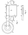
- Fig. l eine Draufsicht auf die Vorrichtung
- Fig. 2 eine Teilansicht des Querträgers in Richtung des Pfeiles A in Fig. l
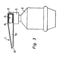
- Fig. 3 einen Querschnitt durch die Absaugdüse mit Geruchsvertilgungsgerät
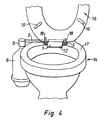
- Fig. 4 eine perspektivische Darstellung des an einer Klosettschüssel befestigten Gerätes
- Die Vorrichtung enthält gemäss den Figuren l und 2 eine Absaugdüse l sowie einen hohlen Quer träger 2, welcher in die Absaugdüse verschiebbar eingesetzt ist und mit dieser durchflussverbunden ist. An dem von der Absaugdüse l abgewandten Ende dieses Querträgers 2 befindet sich ein Befestigungskopf 5, in welchem ein Geruchsvertilgungsgerät 6 befestigt ist. Das andere Ende ist an ihrer Stirnseite l3 durch ein pfropfenartiges Einsatzstück verschlossen. Die Absaugdüse l enthält beidseitig je einen flachen Befestigungsflansch 3 mit Langlöchern 4, zur Anpassung an allenfalls unterschiedliche Lochabstände der Schrauben l8, welche den Ringsitz l6 schwenkbar mit der Klosettschüssel l4 verbinden. Die Langlöcher 4 könnten auch randoffen ausgebildet sein. Somit durchdringen die gleichen Befestigungsschrauben l8, welche den Ringsitz l6 mit dem obern Rand der Klosettschüssel l4 verbinden, die Befestigungsflansche 3 der Absaugdüse l. Die Absaugdüse l befindet sich im Raum zwischen den beiden Befestigungsschrauben l8 und liegt auf dem obern Rand der Klosettschüssel l4 auf.
- Wie aus Figur 3 hervorgeht, enthält die Absaugdüse l innen einen Absaugkanal l0 mit offener Mündung l2, der im montierten Zustand vorne knapp in das Schlüsselinnere hineinragt und so geeignet ist, unangenehme Gase bzw. Gerüche aus dem Schüsselinnern abzusaugen. Der im Querschnitt sich nach hinten vergrössernde Absaugkanal l0 ist hinten durch eine Wand l5 abgeschlossen. In der Absaugdüse l befinden sich an beiden Seiten je eine Oeffnung ll zur Aufnahme des Querträgers 2. Im Bereich des Absaugkanales l0 ist im Querträger 2 ein länglicher Durchbruch 8 vorhanden, sodass also eine Durchflussverbindung zwischen der Mündung l2, dem Kanal l0, dem hohlen Querträger 2 und dem Geruchsvertilgungungsgerät 6 besteht. Der im Querschnitt rechteckige, biegesteife Querträger 2 ist passend aber längsverschiebbar durch die Oeffnungen ll in das Innere der Absaugdüse l eingeschoben. Die Länge des Durchbruches 8 ist kürzer als die Breite des Absaugkanales l0. Der Querträger 2 kann wahlweise links- oder rechtsseitig eingesetzt werden, da die Absaugdüse l beidseitig mit gleichen seitlichen Oeffnungen ll versehen ist. Dabei sind zwei Varianten möglich. Bei der einen Variante ist die Befestigung am Geruchsvertilgungsgerät 6 so ausgebildet, dass der Querträger 2 auch in einer um l80° gedrehten Lage in den Kopf 5 des Gerätes 6 eingesetzt und in diesem gesichert werden kann. Bei der andern Variante ist der Querträger 2 an den beiden Schmalseiten mit zwei lageübereinstimmenden länglichen Durchbrüchen 8 versehen, sodass er bei unveränderter Befestigung des Gerätes 6 wahlweise links- oder rechtsseitig eingeschoben werden kann.
- Bei herabgeklapptem Ringsitz l6 befindet sich somit die Absaugdüse l in dem durch die Gummipuffer l9 od. dgl. gegebenen Zwischenraum zwischen diesem Ringsitz l6 und dem oberen Rand l7 der Klosettschüssel l4.
- Wenn das Geruchsvertilgungsgerät 6 eingeschaltet ist, werden somit überiechende Gase oder Gerüche durch die Absaugdüse l aus der Klosettschüssel l4 abgesaugt und durch die im Geruchsvertilgungsgerät enthaltene Aktivkohle neutralisiert. Die Einschaltung des Motors des Geruchsvertilgungsgerätes 6 kann in an sich bekannter Weise durch Betätigung eines elektrischen Schalters erfolgen; sie könnte indessen auch durch das Herabklappen des Ringsitzes l6, durch Fernsteuerung oder durch die Türverriegelung des Klosettraumes eingeschaltet werden.
- Als Ausführungsvariante ist es möglich, den Kanal 10 nicht keilförmig sondern mit parallelen Wänden auszuführen. Ferner könnte der Querträger 2 eine andere Querschnittsform haben, beispielsweise rund oder oval sein.
Claims (4)
Priority Applications (1)
| Application Number | Priority Date | Filing Date | Title |
|---|---|---|---|
| AT86810371T ATE43386T1 (de) | 1985-09-03 | 1986-08-20 | Vorrichtung zur befestigung eines geruchsvertilgers an einer klosettschuessel. |
Applications Claiming Priority (2)
| Application Number | Priority Date | Filing Date | Title |
|---|---|---|---|
| CH3781/85 | 1985-09-03 | ||
| CH378185 | 1985-09-03 |
Publications (3)
| Publication Number | Publication Date |
|---|---|
| EP0214098A2 true EP0214098A2 (de) | 1987-03-11 |
| EP0214098A3 EP0214098A3 (en) | 1987-05-20 |
| EP0214098B1 EP0214098B1 (de) | 1989-05-24 |
Family
ID=4263344
Family Applications (1)
| Application Number | Title | Priority Date | Filing Date |
|---|---|---|---|
| EP86810371A Expired EP0214098B1 (de) | 1985-09-03 | 1986-08-20 | Vorrichtung zur Befestigung eines Geruchsvertilgers an einer Klosettschüssel |
Country Status (3)
| Country | Link |
|---|---|
| EP (1) | EP0214098B1 (de) |
| AT (1) | ATE43386T1 (de) |
| DE (1) | DE3663550D1 (de) |
Cited By (4)
| Publication number | Priority date | Publication date | Assignee | Title |
|---|---|---|---|---|
| US5488741A (en) * | 1993-09-21 | 1996-02-06 | Hunnicutt, Jr.; Clyde J. | Toilet bowl ventilating and deodorizing apparatus |
| WO1997006315A1 (en) * | 1995-08-09 | 1997-02-20 | Allan Maxwell Ingleton | Exhaust device and method |
| US6233750B1 (en) * | 1997-12-31 | 2001-05-22 | Shane Craig Donald | Toilet bowl ventilating apparatus |
| GB2379462A (en) * | 2001-09-06 | 2003-03-12 | John Kennedy Fletcher | Toilet bowl odour remover |
Family Cites Families (4)
| Publication number | Priority date | Publication date | Assignee | Title |
|---|---|---|---|---|
| US1498789A (en) * | 1923-04-19 | 1924-06-24 | Drouillard Albert | Closet ventilator |
| CA914853A (en) * | 1969-09-16 | 1972-11-21 | A. Duguay Claude | Ventilating toilet seat |
| US4059857A (en) * | 1976-12-20 | 1977-11-29 | Poister Clarence E | Free standing toilet stool ventilating device |
| US4175293A (en) * | 1978-02-06 | 1979-11-27 | Nielson Juan F | Toilet bowl odor removing apparatus and hinge |
-
1986
- 1986-08-20 EP EP86810371A patent/EP0214098B1/de not_active Expired
- 1986-08-20 DE DE8686810371T patent/DE3663550D1/de not_active Expired
- 1986-08-20 AT AT86810371T patent/ATE43386T1/de active
Cited By (5)
| Publication number | Priority date | Publication date | Assignee | Title |
|---|---|---|---|---|
| US5488741A (en) * | 1993-09-21 | 1996-02-06 | Hunnicutt, Jr.; Clyde J. | Toilet bowl ventilating and deodorizing apparatus |
| US5555572A (en) * | 1993-09-21 | 1996-09-17 | Hunnicutt, Jr.; Clyde J. | Toilet bowl ventilating and deodorizing apparatus |
| WO1997006315A1 (en) * | 1995-08-09 | 1997-02-20 | Allan Maxwell Ingleton | Exhaust device and method |
| US6233750B1 (en) * | 1997-12-31 | 2001-05-22 | Shane Craig Donald | Toilet bowl ventilating apparatus |
| GB2379462A (en) * | 2001-09-06 | 2003-03-12 | John Kennedy Fletcher | Toilet bowl odour remover |
Also Published As
| Publication number | Publication date |
|---|---|
| EP0214098B1 (de) | 1989-05-24 |
| EP0214098A3 (en) | 1987-05-20 |
| DE3663550D1 (en) | 1989-06-29 |
| ATE43386T1 (de) | 1989-06-15 |
Similar Documents
| Publication | Publication Date | Title |
|---|---|---|
| DE2556459C2 (de) | Schwenkvorrichtung | |
| DE102012110941A1 (de) | Verschluss zum Verriegeln einer Abdeckung | |
| EP0422678B1 (de) | Gepäckbox | |
| DE102004020925B3 (de) | Schwellerverkleidung für ein Fahrzeug | |
| DE3822050A1 (de) | Tuergriffanordnung an einer fahrzeugtuer | |
| EP0214098A2 (de) | Vorrichtung zur Befestigung eines Geruchsvertilgers an einer Klosettschüssel | |
| EP0038040A1 (de) | Verbindung für die Rinnen eines Bergbau-Kratzförderers | |
| DE102004031004A1 (de) | Feststelleinrichtung für einen aufklappbaren Ladeboden in einem Fahrzeug | |
| DE2641606C2 (de) | Wandkonstruktion für Kabinen, insbesondere für Sanitärkabinen | |
| DE2721348C2 (de) | Halterung für WC-Desodorantien | |
| DE102007051924B4 (de) | Halte-Vorrichtung | |
| EP0615026A1 (de) | Spülvorrichtung für ein Wasserklosett | |
| AT253729B (de) | Einrichtung zur Verkleidung der zwischen Schrank und Zimmerdecke sich ergebenden freien Räume | |
| AT394079B (de) | Loesbare gelenkverbindung zwischen zwei beschlagteilen von fenstern, tueren od. dgl. | |
| DE68919974T2 (de) | Gestell zur Abdeckung eines Lkw-Aufbaues. | |
| DE10044112C2 (de) | Vorrichtung zum Verbinden einer Scheibe mit einem Fensterheber | |
| DE2502999C3 (de) | Steckverbindung, insbesondere zum einendigen Befestigen eines Handgriffes an einer Karosseriewandung bzw. Armlehne eines Kraftfahrzeuges | |
| DE202019100489U1 (de) | Multifunktionale Vorhanghalterung | |
| DE2101235C3 (de) | Aufhängevorrichtung für die Anordnung von Möbelstücken an einer Wand | |
| DE29604768U1 (de) | Verriegelungsvorrichtung für ein Deckenelement | |
| EP1876319B1 (de) | Gleitfuehrung fuer Schiebefluegel oder Abstellschiebefluegel | |
| DE8803427U1 (de) | Regler-Leuchtenkombination für Kühlschränke od.dgl. | |
| DE3125914C2 (de) | ||
| DE19950770B4 (de) | Anordnung eines Türkontaktschalters im Türrahmen eines Fahrzeugs | |
| DE3831045A1 (de) | Schiebedach fuer kraftfahrzeuge |
Legal Events
| Date | Code | Title | Description |
|---|---|---|---|
| PUAI | Public reference made under article 153(3) epc to a published international application that has entered the european phase |
Free format text: ORIGINAL CODE: 0009012 |
|
| AK | Designated contracting states |
Kind code of ref document: A2 Designated state(s): AT BE CH DE FR GB IT LI LU NL SE |
|
| PUAL | Search report despatched |
Free format text: ORIGINAL CODE: 0009013 |
|
| AK | Designated contracting states |
Kind code of ref document: A3 Designated state(s): AT BE CH DE FR GB IT LI LU NL SE |
|
| 17P | Request for examination filed |
Effective date: 19870806 |
|
| RAP3 | Party data changed (applicant data changed or rights of an application transferred) |
Owner name: BRATSCHI, VIKTOR |
|
| 17Q | First examination report despatched |
Effective date: 19880801 |
|
| GRAA | (expected) grant |
Free format text: ORIGINAL CODE: 0009210 |
|
| AK | Designated contracting states |
Kind code of ref document: B1 Designated state(s): AT BE CH DE FR GB IT LI LU NL SE |
|
| PG25 | Lapsed in a contracting state [announced via postgrant information from national office to epo] |
Ref country code: IT Free format text: LAPSE BECAUSE OF FAILURE TO SUBMIT A TRANSLATION OF THE DESCRIPTION OR TO PAY THE FEE WITHIN THE PRE;WARNING: LAPSES OF ITALIAN PATENTS WITH EFFECTIVE DATE BEFORE 2007 MAY HAVE OCCURRED AT ANY TIME BEFORE 2007. THE CORRECT EFFECTIVE DATE MAY BE DIFFERENT FROM THE ONE RECORDED.SCRIBED TIME-LIMIT Effective date: 19890524 Ref country code: GB Effective date: 19890524 Ref country code: NL Effective date: 19890524 Ref country code: BE Effective date: 19890524 Ref country code: SE Effective date: 19890524 Ref country code: FR Free format text: THE PATENT HAS BEEN ANNULLED BY A DECISION OF A NATIONAL AUTHORITY Effective date: 19890524 |
|
| REF | Corresponds to: |
Ref document number: 43386 Country of ref document: AT Date of ref document: 19890615 Kind code of ref document: T |
|
| REF | Corresponds to: |
Ref document number: 3663550 Country of ref document: DE Date of ref document: 19890629 |
|
| PG25 | Lapsed in a contracting state [announced via postgrant information from national office to epo] |
Ref country code: AT Effective date: 19890820 |
|
| PG25 | Lapsed in a contracting state [announced via postgrant information from national office to epo] |
Ref country code: LU Free format text: LAPSE BECAUSE OF NON-PAYMENT OF DUE FEES Effective date: 19890831 |
|
| EN | Fr: translation not filed | ||
| NLV1 | Nl: lapsed or annulled due to failure to fulfill the requirements of art. 29p and 29m of the patents act | ||
| PLBE | No opposition filed within time limit |
Free format text: ORIGINAL CODE: 0009261 |
|
| STAA | Information on the status of an ep patent application or granted ep patent |
Free format text: STATUS: NO OPPOSITION FILED WITHIN TIME LIMIT |
|
| PGFP | Annual fee paid to national office [announced via postgrant information from national office to epo] |
Ref country code: DE Payment date: 19900404 Year of fee payment: 4 |
|
| 26N | No opposition filed | ||
| PG25 | Lapsed in a contracting state [announced via postgrant information from national office to epo] |
Ref country code: DE Effective date: 19910501 |
|
| PGFP | Annual fee paid to national office [announced via postgrant information from national office to epo] |
Ref country code: CH Payment date: 19940722 Year of fee payment: 9 |
|
| PG25 | Lapsed in a contracting state [announced via postgrant information from national office to epo] |
Ref country code: LI Effective date: 19950831 Ref country code: CH Effective date: 19950831 |
|
| REG | Reference to a national code |
Ref country code: CH Ref legal event code: PL |