EP0210327A1 - Explosionskammer - Google Patents
Explosionskammer Download PDFInfo
- Publication number
- EP0210327A1 EP0210327A1 EP86102990A EP86102990A EP0210327A1 EP 0210327 A1 EP0210327 A1 EP 0210327A1 EP 86102990 A EP86102990 A EP 86102990A EP 86102990 A EP86102990 A EP 86102990A EP 0210327 A1 EP0210327 A1 EP 0210327A1
- Authority
- EP
- European Patent Office
- Prior art keywords
- chamber
- explosion chamber
- chamber according
- explosion
- foundation
- Prior art date
- Legal status (The legal status is an assumption and is not a legal conclusion. Google has not performed a legal analysis and makes no representation as to the accuracy of the status listed.)
- Granted
Links
Images
Classifications
-
- B—PERFORMING OPERATIONS; TRANSPORTING
- B21—MECHANICAL METAL-WORKING WITHOUT ESSENTIALLY REMOVING MATERIAL; PUNCHING METAL
- B21D—WORKING OR PROCESSING OF SHEET METAL OR METAL TUBES, RODS OR PROFILES WITHOUT ESSENTIALLY REMOVING MATERIAL; PUNCHING METAL
- B21D26/00—Shaping without cutting otherwise than using rigid devices or tools or yieldable or resilient pads, i.e. applying fluid pressure or magnetic forces
- B21D26/02—Shaping without cutting otherwise than using rigid devices or tools or yieldable or resilient pads, i.e. applying fluid pressure or magnetic forces by applying fluid pressure
- B21D26/06—Shaping without cutting otherwise than using rigid devices or tools or yieldable or resilient pads, i.e. applying fluid pressure or magnetic forces by applying fluid pressure by shock waves
- B21D26/08—Shaping without cutting otherwise than using rigid devices or tools or yieldable or resilient pads, i.e. applying fluid pressure or magnetic forces by applying fluid pressure by shock waves generated by explosives, e.g. chemical explosives
Definitions
- the invention relates to an explosion chamber according to the preamble of the main claim.
- a generic plant is described in DE-R-16 52 627.
- the work table is supported on a concrete foundation with the interposition of spring elements.
- the top of the work table is coated with a rubber pad, which in turn should be equipped with a recess on its top to accommodate a layer of sand.
- the work table is unstable and has a relatively short lifespan, so that no economy can be achieved with such systems in the technological production process and larger workpieces cannot be machined.
- the blasting chamber consists of a spherical container, which rests on a relatively small foundation, the container being preferably supported on this small foundation again with the interposition of springs.
- the container has a small internal volume and is not used for the industrial processing of workpieces.
- the invention has for its object to provide a system in which the explosion processing of metals can be carried out in the industrial production program and in which not only the actual explosive chamber but also the work table has a long service life and thus high performance, while at the same time being environmentally harmful is kept to a minimum by sound and seismic waves.
- the invention achieves that the quasi-elastic design of the work table and its insertion in and connection to the foundation create a long-lasting work table which is capable of absorbing the waves which occur, while at the same time also Foundation is used directly to destroy these seismic waves. It becomes a large free space, i.e. Work space, created, the actual steel dome can be designed to be movable or tiltable and can thus be guided either in a working position above the work table or in a release position.
- the use of a vacuum system at the same time achieves that the sealing and thus support of the steel dome on the foundation is improved, since due to the vacuum prevailing within the steel dome, the atmospheric pressure improved the position of the steel dome on the foundation.
- the vacuum system in the interior acts in a manner known per se in such a way that pressure waves are reduced and the overall system thereby becomes more environmentally friendly.
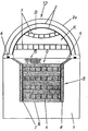
- 1 denotes a correspondingly heavy foundation, for example made of concrete; on which a hood 12 rests, with the interposition of appropriate seals 6, the hood 12 creating the actual chamber cavity K.
- This chamber cavity can be evacuated by a vacuum system, not shown in the drawing, so that the hood 12 is thereby additionally pressed onto the seals 6 in a sealing manner.
- a recess is provided within the foundation 1, which receives a work table 11 which is made up of different layers, the top layer creating the workpiece support surface 9.
- the various layers 4 consist of materials which convert the potential energy of the pressure wave into the kinetic energy of the installation materials, the average density of the successive layers alternating between values of 500 to 15000 kg / m.
- the layers can be formed continuously in the horizontal direction, but can also - as shown in the drawing - be formed by individual cassette-like receiving compartments.
- the cavity provided in the foundation 1 has in its circumferential regions a filling 8, preferably made of sand or the like, which is separated from the layers 4 by a wall 3, which is in one piece formed as a large square can, but loose, ie without any connection to the foundation, is inserted into the corresponding cavity.
- This sand or trickle grain filling also consists of materials that convert the potential energy of the pressure wave into the kinetic energy of the paving materials.
- the layers 4 can consist of wood, wood shavings, metal shavings, sand or the like, whereby these materials can be mixed appropriately and can be pre-compressed, the sand filling in these compressed materials being able to move when the waves occur.
- baffles 5 which extend obliquely upwards in the edge regions and thus protect the seals 6 and the connection regions of the hood 12 towards the foundation.
- baffles can also be formed from cassette-shaped metal elements which are open to the outside and can nevertheless have a sand or trickle grain filling.
- the layers 4 are supported on the floor 14 of the space recessed in the foundation 1, also with the interposition of a layer of sand or grit.
- the actual chamber cavity K is closed at the top by sheet metal jackets 2, two such sheet metal jackets being provided in the exemplary embodiment shown, between which a vibration-absorbing mass is likewise introduced.
- a seal in the chamber cavity K Elements exist, wherein the extension of these cassette-shaped ceiling elements can be horizontal or - as shown in the drawing - also slightly curved. If the slightly arched interception system is used in the upper area of the hood 12, the side which is directed toward the sheet metal sheaths 2 can be closed and the space B thus created can also have sand filling.
- the crane system that may be required to move the hood 12, like the vacuum system, is not shown in the drawing.
Abstract
Description
- Die Erfindung bezieht sich auf eine Explosionskammer gemäß dem Oberbegriff des Hauptanspruches.
- Eine gattungsbildende Anlage wird in der DE-R-16 52 627 beschrieben. Bei dieser bekannten Anlage stützt sich der Arbeitstisch unter Zwischenschaltung von Federelementen auf einem Betonfundament ab. Die Oberseite des Arbeitstisches ist mit einer Gummiauflage beschichtet, die selbst wiederum an ihrer Oberseite mit einer Ausnehmung zur Aufnahme einer Sandschicht ausgerüstet sein soll. Der Arbeitstisch ist unstabil und weist eine relativ kurze Lebensdauer auf, so daß mit solchen Anlagen im technologischen Fertigungsablauf keine Wirtschaftlichkeit erzielbar ist und größere Werkstücke nicht bearbeitet werden können.
- Aus der DE-A-19 33 276 ist eine Vorrichtung zum Verformen von Großronden mittels Druckwellen bekannt, die mit einem wassergefüllten Sprengbehälter arbeitet. Auch hier sind zwischen dem eigentlichen Fundament und dem Arbeitstisch Federn eingeschaltet, die eine elastische Abstützung des Arbeitstisches gegenüber dem relativ steifen und starren Fundament erbringen sollen, aber einen unstabilen Arbeitstisch schaffen. Auch hier treten bei großtechnischen Anlagen sofort Zerstörungen dieser elastischen Lagerungen auf, die die Anlage betriebswirtschaftlich nicht einsatzfähig machen.
- Die gleichen Ausführungen treffen für eine Anlage gemäß der DE-A-26 45 347 zu. Insbesondere ist bei dieser Anlage nachteilig, daß sich der Arbeitstisch aus mehreren übereinander angeordneten Platten zusammensetzt, die durch spezielle Metallführungsstäbe verbunden sind.
- Schließlich ist es aus der DE-A-15 27 523 bekannt, die eigentliche Sprengkammer nach Einbringen des zu bearbeitenden Werkstückes auf Vakuum leerzupumpen, um derart Stoß- und Schallwellen in der Atmosphäre und die seismischen Wellen im Erdboden weitgehend zu vermeiden. Hierbei besteht die Sprengkammer aus einem kugelförmigen Behälter, der auf einem relativ kleinen Fundament aufruht, wobei vorzugsweise die Abstützung des Behälters an diesem kleinen Fundament wiederum unter Zwischenschaltung von Federn erfolgen soll. Der Behälter weist ein geringes Innenvolumen auf und dient nicht der großtechnischen Bearbeitung von Werkstücken.
- Der Erfindung liegt die Aufgabe zugrunde, eine Anlage zu schaffen, bei welcher im großtechnischen Fertigungsprogramm die Explosionsbearbeitung von Metallen vorgenommen werden kann und bei welcher nicht nur die eigentliche Sprengkammer, sondern auch der Arbeitstisch eine hohe Lebensdauer und damit hohe Leistungsfähigkeit aufweist, wobei gleichzeitig die Umweltbelastung durch Schall und seismische Wellen auf ein Minimum beschränkt wird.
- Diese der Erfindung zugrundeliegende Aufgabe wird durch die Merkmalskombination gemäß dem Hauptanspruch gelöst.
- Mit anderen Worten ausgedrückt: Durch die Erfindung wird erreicht, daß durch die quasi elastische Ausbildung des Arbeitstisches und sein Einlassen im und Verbinden mit dem Fundament ein langlebiger Arbeitstisch geschaffen wird, der in der Lage ist, die auftretenden Wellen zu absorbieren, wobei gleichzeitig auch das Fundament unmittelbar mit herangezogen wird, um diese seismischen Wellen zu vernichten. Es wird ein großer freier Raum, d.h. Arbeitsraum, geschaffen, wobei die eigentliche Stahlkuppel verfahrbar ausgebildet sein kann oder kippbar ausgebildet sein kann und somit entweder in einer Arbeitsstellung über dem Arbeitstisch oder in eine Freigabestellung führbar ist. Durch den Einsatz einer in vertikalen Richtung wirkenden und die Stahlkuppel gegenüber dem Fundament abdichtenden Dichtung wird dabei gleichzeitig im Einsatz einer Vakuumanlage erreicht, daß die Abdichtung und damit Abstützung der Stahlkuppel auf dem Fundament verbessert wird, da aufgrund des innerhalb der Stahlkuppel herrschenden Vakuums der atmosphärische Druck die Anlage der Stahlkuppel am Fundament verbessert. Gleichzeitig wirkt die Vakuumanlage im Inneren in an sich bekannter Weise dahingehend, daß Druckwellen vermindert werden und dadurch die Gesamtanlage umweltfreundlicher wird.
- Durch die Anordnung einer die Stahlkuppel übergreifenden Krananlage, ist ein einfaches Beschicken des Arbeitstisches möglich, so daß auch große Werkstücke gehandhabt werden können.
- Ein Ausführungsbeispiel der Erfindung wird nachfolgend anhand der Zeichnung erläutert.
- In der Zeichnung ist mit 1 ein entsprechend schweres, beispielsweise aus Beton bestehendes Fundament bezeichnet; auf dem eine Haube 12 aufruht, und zwar unter Zwischenschaltung entsprechender Dichtungen 6, wobei die Haube 12 den eigentlichen Kammerhohlraum K schafft.
- Dieser Kammerhohlraum kann durch eine in der Zeichnung nicht dargestellte Vakuumanlage evakuiert werden, so daß dadurch zusätzlich die Haube 12 abdichtend auf die Dichtungen 6 aufgepreßt wird.
- Innerhalb des Fundamentes 1 ist eine Ausnehmung vorgesehen, die einen Arbeitstisch 11 aufnimmt, der aus verschiedenen Schichten aufgebaut ist, wobei die oberste Schicht die Werkstückauflagefläche 9 schafft. Die verschiedenen Schichten 4 bestehen aus Werkstoffen, die die potentielle Energie der Druckwelle in kinetische Energie der Einbaumaterialien umwandelt, wobei die mittlere Dichte der aufeinanderfolgenden Schichten zwischen Werten von 500 bis 15000 kg/m wechselt. Die Schichten können dabei durchgehend in horizontaler Richtung ausgebildet sein, können aber auch - wie dies in der Zeichnung dargestellt ist - durch einzelne kassettenartige Aufnahmefächer gebildet werden.
- Der im Fundament 1 vorgesehene Hohlraum weist in seinen Umfangsbereichen eine vorzugsweise aus Sand od. dgl. bestehende Füllung 8 auf, die gegenüber den Schichten 4 durch eine Wand 3 abgetrennt ist, die zwar als großes Viereck einteilig ausgebildet sein kann, aber lose, d.h. ohne jede Verbindung mit dem Fundament, in den entsprechenden Hohlraum eingesetzt ist. Diese Sand- oder Rieselkornfüllung besteht ebenfalls aus Materialien, die die potentielle Energie der Druckwelle in kinetische Energie der Einbaumaterialien umwandeln. Die Schichten 4 können dabei aus Holz, Holzspänen, Metallspänen, Sand od. dgl. bestehen, wobei diese Materialien entsprechend gemischt sein können und vorverdichtet sein können, wobei bei Auftreten der Wellen die Sandfüllung in diesen verdichteten Vormaterialien sich bewegen kann.
- Der Übergang von der Werkstückauflagefläche zu den Randbereichen des Kammerhohlraumes K wird durch sich in den Randbereichen schräg nach oben erstreckende Leitbleche 5 gebildet, die damit einen Schutz der Dichtungen 6 und der Verbindungsbereiche der Haube 12 zum Fundament hin bewirken. Auch diese Leitbleche können aus kassettenförmigen Metallelementen gebildet sein, die nach außen hin offen sind und trotzdem aber eine Sand- oder Rieselkornfüllung aufweisen können.
- Die Schichten 4 stützen sich am Boden 14 des im Fundament 1 ausgenommenen Raumes ebenfalls unter Zwischenschaltung einer Schicht aus Sand oder Rieselkorn ab.
- Der eigentliche Kammerhohlraum K wird nach oben hin durch Blechmäntel 2 abgeschlossen, wobei in dem dargestellten Ausführungsbeispiel zwei solcher Blechmäntel vorgesehen sind, zwischen denen ebenfalls eine schwingungsabsorbierende Masse eingebracht wird. Zusätzlich ist in dem Kammerhohlraum K ein Ab-Elementen besteht, wobei die Erstreckung dieser kassettenfbrmig ausgebildeten Deckenelemente horizontal oder - wie in der Zeichnung dargestellt - auch leicht gewölbt sein kann. Wird das leicht gewölbte Abfangsystem im oberen Bereich der Haube 12 eingesetzt, kann die zu den Blechmanteln 2 hingerichtete Seite verschlossen sein und dann der so geschaffene Raum B ebenfalls eine Sandfullung aufweisen.
- Das ganze kann nach außen hin dann durch einen zusatzlichen Blechmantel 2a abgeschlossen werden.
- Die ggf. zum Bewegen der Haube 12 erforderliche Krananlage ist ebenso wie die Vakuumanlage in der Zeichnung nicht dargestellt.
Claims (15)
Priority Applications (1)
| Application Number | Priority Date | Filing Date | Title |
|---|---|---|---|
| AT86102990T ATE63072T1 (de) | 1985-08-02 | 1986-03-06 | Explosionskammer. |
Applications Claiming Priority (2)
| Application Number | Priority Date | Filing Date | Title |
|---|---|---|---|
| DE3527730 | 1985-08-02 | ||
| DE3527730A DE3527730C1 (de) | 1985-08-02 | 1985-08-02 | Explosionskammer |
Publications (2)
| Publication Number | Publication Date |
|---|---|
| EP0210327A1 true EP0210327A1 (de) | 1987-02-04 |
| EP0210327B1 EP0210327B1 (de) | 1991-05-02 |
Family
ID=6277488
Family Applications (1)
| Application Number | Title | Priority Date | Filing Date |
|---|---|---|---|
| EP86102990A Expired - Lifetime EP0210327B1 (de) | 1985-08-02 | 1986-03-06 | Explosionskammer |
Country Status (3)
| Country | Link |
|---|---|
| EP (1) | EP0210327B1 (de) |
| AT (1) | ATE63072T1 (de) |
| DE (2) | DE3527730C1 (de) |
Families Citing this family (2)
| Publication number | Priority date | Publication date | Assignee | Title |
|---|---|---|---|---|
| DE3928241C1 (en) * | 1989-08-26 | 1990-07-05 | Heinrich Dr. Moresnet Chapelle Be Hampel | Explosion chamber for metal processing - has steel upper section with impact absorbing lining |
| DE10204815B4 (de) * | 2002-02-06 | 2005-09-15 | Eisenmann Maschinenbau Gmbh & Co. Kg | Vorrichtung zur Entsorgung gefährlicher oder hochenergetischer Materialien |
Citations (7)
| Publication number | Priority date | Publication date | Assignee | Title |
|---|---|---|---|---|
| FR1503072A (fr) * | 1965-11-30 | 1967-11-24 | Beteiligungs & Patentverw Gmbh | Procédé et dispositif d'usinage de métaux par explosion |
| FR1555786A (de) * | 1967-12-06 | 1969-01-31 | ||
| DE1933276A1 (de) * | 1969-07-01 | 1971-01-14 | Atlas Mak Maschb Gmbh | Vorrichtung zum Verformen von Grossronden mittels Druckwellen |
| DE1652627A1 (de) * | 1968-01-20 | 1971-07-15 | Krupp Gmbh | Detonationskammer zur Explosionsbearbeitung von Metallen |
| DE2645347A1 (de) * | 1976-10-07 | 1978-04-13 | Inst Gidrodinamiki Sibirskogo | Anlage zur explosionsbearbeitung von werkstoffen |
| DE3310046A1 (de) * | 1983-03-19 | 1984-09-20 | Special'noe konstruktorskoe bjuro gidroimpul'snoj techniki Sibirskogo otdelenija Akademii Nauk SSSR, Novosibirsk | Kammer zur explosionsbearbeitung von stoffen |
| DE3314146A1 (de) * | 1983-04-19 | 1984-10-25 | Sp K Byuro Gidroimpuls Tekh | Vorrichtung zum explosionsbearbeiten von werkstoffen |
Family Cites Families (1)
| Publication number | Priority date | Publication date | Assignee | Title |
|---|---|---|---|---|
| DE1527523A1 (de) * | 1965-11-30 | 1969-06-26 | Krupp Gmbh | Verfahren und Vorrichtung zur Explosivbearbeitung von Metallen |
-
1985
- 1985-08-02 DE DE3527730A patent/DE3527730C1/de not_active Expired
-
1986
- 1986-03-06 AT AT86102990T patent/ATE63072T1/de not_active IP Right Cessation
- 1986-03-06 EP EP86102990A patent/EP0210327B1/de not_active Expired - Lifetime
- 1986-03-06 DE DE8686102990T patent/DE3679007D1/de not_active Expired - Fee Related
Patent Citations (7)
| Publication number | Priority date | Publication date | Assignee | Title |
|---|---|---|---|---|
| FR1503072A (fr) * | 1965-11-30 | 1967-11-24 | Beteiligungs & Patentverw Gmbh | Procédé et dispositif d'usinage de métaux par explosion |
| FR1555786A (de) * | 1967-12-06 | 1969-01-31 | ||
| DE1652627A1 (de) * | 1968-01-20 | 1971-07-15 | Krupp Gmbh | Detonationskammer zur Explosionsbearbeitung von Metallen |
| DE1933276A1 (de) * | 1969-07-01 | 1971-01-14 | Atlas Mak Maschb Gmbh | Vorrichtung zum Verformen von Grossronden mittels Druckwellen |
| DE2645347A1 (de) * | 1976-10-07 | 1978-04-13 | Inst Gidrodinamiki Sibirskogo | Anlage zur explosionsbearbeitung von werkstoffen |
| DE3310046A1 (de) * | 1983-03-19 | 1984-09-20 | Special'noe konstruktorskoe bjuro gidroimpul'snoj techniki Sibirskogo otdelenija Akademii Nauk SSSR, Novosibirsk | Kammer zur explosionsbearbeitung von stoffen |
| DE3314146A1 (de) * | 1983-04-19 | 1984-10-25 | Sp K Byuro Gidroimpuls Tekh | Vorrichtung zum explosionsbearbeiten von werkstoffen |
Also Published As
| Publication number | Publication date |
|---|---|
| DE3679007D1 (de) | 1991-06-06 |
| EP0210327B1 (de) | 1991-05-02 |
| ATE63072T1 (de) | 1991-05-15 |
| DE3527730C1 (de) | 1986-12-18 |
Similar Documents
| Publication | Publication Date | Title |
|---|---|---|
| DE69630895T2 (de) | Verfahren und vorrichtung zum einsperren und zum unterdrücken von sprengstoffdetonationen | |
| DE2031658C3 (de) | Panzerungswand mit schottähnlichen Kammern | |
| EP0143212B1 (de) | Transport- und Lagerbehälter für radioaktives Material | |
| CH671071A5 (de) | ||
| EP0210327B1 (de) | Explosionskammer | |
| DE2925680C2 (de) | Auffangvorrichtung für schmelzende Brennelemente eines Atomreaktors | |
| DE2356060C3 (de) | Wirbelschichtofen für die Verbrennung von teilweise entwässertem Schlamm | |
| DE2147897A1 (de) | Verfahren und Anlage zur Mullbe seitigung | |
| DE2025709C3 (de) | Vorrichtung zur Herstellung von Blöcken | |
| DE3809535C2 (de) | Rollbahn für einen drehbaren Trichter | |
| EP0290766A2 (de) | Gasspülstein | |
| DE2538655A1 (de) | Aus formgepressten fasern bestehendes futter als daempfender einsatz in einer giessform | |
| EP0128336B1 (de) | Vorrichtung zum Verdichten von Giessereiformsand | |
| DE2645347C3 (de) | Anlage zur Explosionsbearbeitung von Werkstoffen | |
| DE2427081A1 (de) | Filtrationszelle fuer fluide | |
| DE3710679C1 (en) | Explosion chamber | |
| DE2414412C3 (de) | Einrichtung zur Explosivbearbeitung von Metallen | |
| DE3502168C2 (de) | ||
| DE3808419C1 (en) | Armour plate | |
| DE4417312A1 (de) | Schutzschicht für Deponie- und andere Abdichtungen | |
| DE2414412B2 (de) | Einrichtung zur explosivbearbeitung von metallen | |
| DE102017112150A1 (de) | Explosionssicheres Gehäuse mit innerer Druckreduzierung | |
| DE1652627C3 (de) | Detonationskammer zur Durchführung von Explosionsplattierungen und -härtungen von Metallen | |
| DE1609408C (de) | Bentonithaltige Dichtungsplatte | |
| DE2364984C3 (de) | Explosionsumformungsanlage |
Legal Events
| Date | Code | Title | Description |
|---|---|---|---|
| PUAI | Public reference made under article 153(3) epc to a published international application that has entered the european phase |
Free format text: ORIGINAL CODE: 0009012 |
|
| AK | Designated contracting states |
Kind code of ref document: A1 Designated state(s): AT BE CH DE FR GB IT LI NL SE |
|
| RAP1 | Party data changed (applicant data changed or rights of an application transferred) |
Owner name: GVM VERBUNDMETALLE GMBH & CO. KG |
|
| RIN1 | Information on inventor provided before grant (corrected) |
Inventor name: HAMPEL, HEINRICH, DR.-ING. |
|
| 17P | Request for examination filed |
Effective date: 19870730 |
|
| 17Q | First examination report despatched |
Effective date: 19890210 |
|
| 19A | Proceedings stayed before grant |
Effective date: 19900406 |
|
| RAP1 | Party data changed (applicant data changed or rights of an application transferred) |
Owner name: HAMPEL, HEINRICH, DR. |
|
| RAP3 | Party data changed (applicant data changed or rights of an application transferred) |
Owner name: HAMPEL, HEINRICH, DR. |
|
| 19F | Resumption of proceedings before grant (after stay of proceedings) |
Effective date: 19901030 |
|
| GRAA | (expected) grant |
Free format text: ORIGINAL CODE: 0009210 |
|
| AK | Designated contracting states |
Kind code of ref document: B1 Designated state(s): AT BE CH DE FR GB IT LI NL SE |
|
| PG25 | Lapsed in a contracting state [announced via postgrant information from national office to epo] |
Ref country code: IT Free format text: LAPSE BECAUSE OF FAILURE TO SUBMIT A TRANSLATION OF THE DESCRIPTION OR TO PAY THE FEE WITHIN THE PRE;WARNING: LAPSES OF ITALIAN PATENTS WITH EFFECTIVE DATE BEFORE 2007 MAY HAVE OCCURRED AT ANY TIME BEFORE 2007. THE CORRECT EFFECTIVE DATE MAY BE DIFFERENT FROM THE ONE RECORDED.SCRIBED TIME-LIMIT Effective date: 19910502 Ref country code: BE Effective date: 19910502 Ref country code: SE Effective date: 19910502 |
|
| REF | Corresponds to: |
Ref document number: 63072 Country of ref document: AT Date of ref document: 19910515 Kind code of ref document: T |
|
| REF | Corresponds to: |
Ref document number: 3679007 Country of ref document: DE Date of ref document: 19910606 |
|
| ET | Fr: translation filed | ||
| GBT | Gb: translation of ep patent filed (gb section 77(6)(a)/1977) | ||
| PLBE | No opposition filed within time limit |
Free format text: ORIGINAL CODE: 0009261 |
|
| STAA | Information on the status of an ep patent application or granted ep patent |
Free format text: STATUS: NO OPPOSITION FILED WITHIN TIME LIMIT |
|
| PG25 | Lapsed in a contracting state [announced via postgrant information from national office to epo] |
Ref country code: LI Effective date: 19920331 Ref country code: CH Effective date: 19920331 |
|
| 26N | No opposition filed | ||
| REG | Reference to a national code |
Ref country code: CH Ref legal event code: PL |
|
| PGFP | Annual fee paid to national office [announced via postgrant information from national office to epo] |
Ref country code: GB Payment date: 19960216 Year of fee payment: 11 |
|
| PGFP | Annual fee paid to national office [announced via postgrant information from national office to epo] |
Ref country code: AT Payment date: 19960325 Year of fee payment: 11 |
|
| PG25 | Lapsed in a contracting state [announced via postgrant information from national office to epo] |
Ref country code: AT Effective date: 19970306 Ref country code: GB Effective date: 19970306 |
|
| PGFP | Annual fee paid to national office [announced via postgrant information from national office to epo] |
Ref country code: FR Payment date: 19970319 Year of fee payment: 12 |
|
| PGFP | Annual fee paid to national office [announced via postgrant information from national office to epo] |
Ref country code: NL Payment date: 19970331 Year of fee payment: 12 |
|
| PGFP | Annual fee paid to national office [announced via postgrant information from national office to epo] |
Ref country code: DE Payment date: 19970530 Year of fee payment: 12 |
|
| GBPC | Gb: european patent ceased through non-payment of renewal fee |
Effective date: 19970306 |
|
| PG25 | Lapsed in a contracting state [announced via postgrant information from national office to epo] |
Ref country code: FR Free format text: THE PATENT HAS BEEN ANNULLED BY A DECISION OF A NATIONAL AUTHORITY Effective date: 19980331 |
|
| PG25 | Lapsed in a contracting state [announced via postgrant information from national office to epo] |
Ref country code: NL Free format text: LAPSE BECAUSE OF NON-PAYMENT OF DUE FEES Effective date: 19981001 |
|
| NLV4 | Nl: lapsed or anulled due to non-payment of the annual fee |
Effective date: 19981001 |
|
| PG25 | Lapsed in a contracting state [announced via postgrant information from national office to epo] |
Ref country code: DE Free format text: LAPSE BECAUSE OF NON-PAYMENT OF DUE FEES Effective date: 19981201 |
|
| REG | Reference to a national code |
Ref country code: FR Ref legal event code: ST |