EP0209537B1 - Storage conveyor - Google Patents
Storage conveyor Download PDFInfo
- Publication number
- EP0209537B1 EP0209537B1 EP86900222A EP86900222A EP0209537B1 EP 0209537 B1 EP0209537 B1 EP 0209537B1 EP 86900222 A EP86900222 A EP 86900222A EP 86900222 A EP86900222 A EP 86900222A EP 0209537 B1 EP0209537 B1 EP 0209537B1
- Authority
- EP
- European Patent Office
- Prior art keywords
- chain
- workpieces
- housing
- location
- load
- Prior art date
- Legal status (The legal status is an assumption and is not a legal conclusion. Google has not performed a legal analysis and makes no representation as to the accuracy of the status listed.)
- Expired
Links
- 238000004519 manufacturing process Methods 0.000 description 7
- 230000001174 ascending effect Effects 0.000 description 3
- 230000001419 dependent effect Effects 0.000 description 1
- 238000009434 installation Methods 0.000 description 1
- 238000000034 method Methods 0.000 description 1
- 238000012986 modification Methods 0.000 description 1
- 230000004048 modification Effects 0.000 description 1
- 230000000284 resting effect Effects 0.000 description 1
Images


Classifications
-
- B—PERFORMING OPERATIONS; TRANSPORTING
- B65—CONVEYING; PACKING; STORING; HANDLING THIN OR FILAMENTARY MATERIAL
- B65G—TRANSPORT OR STORAGE DEVICES, e.g. CONVEYORS FOR LOADING OR TIPPING, SHOP CONVEYOR SYSTEMS OR PNEUMATIC TUBE CONVEYORS
- B65G21/00—Supporting or protective framework or housings for endless load-carriers or traction elements of belt or chain conveyors
- B65G21/16—Supporting or protective framework or housings for endless load-carriers or traction elements of belt or chain conveyors for conveyors having endless load-carriers movable in curved paths
- B65G21/18—Supporting or protective framework or housings for endless load-carriers or traction elements of belt or chain conveyors for conveyors having endless load-carriers movable in curved paths in three-dimensionally curved paths
-
- B—PERFORMING OPERATIONS; TRANSPORTING
- B65—CONVEYING; PACKING; STORING; HANDLING THIN OR FILAMENTARY MATERIAL
- B65G—TRANSPORT OR STORAGE DEVICES, e.g. CONVEYORS FOR LOADING OR TIPPING, SHOP CONVEYOR SYSTEMS OR PNEUMATIC TUBE CONVEYORS
- B65G1/00—Storing articles, individually or in orderly arrangement, in warehouses or magazines
- B65G1/02—Storage devices
- B65G1/04—Storage devices mechanical
- B65G1/12—Storage devices mechanical with separate article supports or holders movable in a closed circuit to facilitate insertion or removal of articles the articles being books, documents, forms or the like
- B65G1/133—Storage devices mechanical with separate article supports or holders movable in a closed circuit to facilitate insertion or removal of articles the articles being books, documents, forms or the like the circuit being confined in a horizontal plane
-
- B—PERFORMING OPERATIONS; TRANSPORTING
- B65—CONVEYING; PACKING; STORING; HANDLING THIN OR FILAMENTARY MATERIAL
- B65G—TRANSPORT OR STORAGE DEVICES, e.g. CONVEYORS FOR LOADING OR TIPPING, SHOP CONVEYOR SYSTEMS OR PNEUMATIC TUBE CONVEYORS
- B65G2207/00—Indexing codes relating to constructional details, configuration and additional features of a handling device, e.g. Conveyors
- B65G2207/24—Helical or spiral conveying path
Definitions
- This invention relates to transportable storage magazines, in the form of conveyors, for workpieces, such as components, to be supplied seriatim to machines for manufacturing or other operations to be carried out automatically.
- FR-A-2387867 discloses a storage conveyor according to the pre-characterising portion of claim 1.
- This known storage conveyor comprises a continuous chain mounted on a double helix and carrying bearing plates or pallets for workpieces.
- the apparatus put into practice has a load/ unload station on the top run of each helix and the pallets are supported at one side by the chain and at the other side on a guideway.
- objects are thrown off the pallet when the chain goes round a bend, for example when reversing its direction around a sprocket, due to centrifugal force, and also the location of the load/unload stations is not convenient for robot machines.
- a housing is illustrated at 1 and is shown as including a drive assembly 2 including a motor 3 and a reduction gear box 4 having an output shaft 5 driving a sprocket 6.
- the sprocket 6 drives a chain 7 entraining a pair of sprockets 8 each driving a conveyor drive shaft 9.
- Each drive shaft 9 has an associated idler shaft 10.
- the shafts 9 and 10 are mounted in the housing by means of bearings which are not shown.
- the shafts 9 and 10 also carry sprockets on which there is mounted an endless conveyor chain 11. This carries pallets or other supports 12 for components to be stored within the housing 1.
- the top sprocket of one drive shaft 9 is fast with the shaft and the bottom sprocket of the other drive shaft 9 is also fast therewith.
- the remaining sprockets on the shafts 9,10 are rotatable to allow for variations in tension along the chain 11.
- the shafts 9,10 are angled at between 2° and 5° to the vertical with a 1° tolerance.
- each shaft and its associated idler shaft are 1420 mm apart, with the pairs of drive shafts and idler shafts being 535 mm apart.
- the sprockets are spaced at 115 mm intervals to give a drop of 115 mm on a descending run.
- the sprockets are 235 mm outside diameter.
- An opening in the housing provides a station 13 for loading and unloading components or workpieces from the pallets 12 on a top run of a helix, and an extension 14 to the housing 1 projects from the housing 1 at a lower point and has an open top so as to provide access to the chain 11, thereby forming a second load/unload station (see Figure 7).
- the endless chain 11 is wound on the sprockets so that, starting from the load/unload station 13 which is at the top of one elongate helix provided by the sprockets on the shafts 9 and 10, the chain passes round the uppermost sprocket on the shaft 10 and then descends one level as indicated by the run 11 a to pass round the second sprocket on the shaft 9 on its own side of the housing 1.
- the chain then continues successively in this manner until it reaches the lowermost of the sprockets on the shaft 9, whence it passes over the lowermost sprocket on the shaft 10 and along a run 11 b so as to pass into the other helix onto the sprocket 40, whence it starts to climb in similar manner through the sprockets 41, 42, 43...44, 45, 46 until it reaches the uppermost sprocket 47 on the drive shaft 9 (see Figure 6), whence it passes back via a run 11c to the uppermost layer on the first or front helix.
- a sprocket is not provided on the shaft 10 at this level.
- a chain guide 48 supporting the chain is provided to extend horizontally from inline with the shaft 10 towards the sprocket 49 so that the chain in the ascending run is parallel to the chain in the ascending runs above and below.
- the housing 1 may be made to accommodate a large number, e.g. 250 to 500, of components or workpieces to be presented serially at the loading/unloading station provided by the extension 14.
- components will be loaded one at a time via the load/unload station 13, and the conveyor will be stepped on one position at a time on each loading, either manually or automatically, and this process will continue either until enough components have been loaded, or until the storage magazine is full with every pallet occupied.
- the conveyor may be run continuously during this loading at a speed suitable for manual loading.
- the loaded conveyor will then be taken to a machine to which the workpieces have to be fed one at a time for the manufacturing step to be carried out.
- the machine will be arranged so as to be properly aligned with the automatic load/unload device on the machine which will collect the components one at a time from the projecting extension 14. It will normally take a component which is presented to it, work on it, replace it on its own pallet 12 and then by means of a control on the machine itself, will cause the conveyor to step round one place, or until a loaded pallet is presented, when it will repeat the operation.
- the workpieces may be replaced on the pallets in different positions from that from which they were taken so that the machine can automatically sense when it has completed work on all the loaded components.
- the housing may then be detached from that particular machine and moved to the next manufacturing stage, and a fresh housing 1 with more components may be brought up if required. In this manner, the components only have to be loaded into the housing once, and may then be taken serially to the various manufacturing operations, before the finished components are unloaded.
- the final components may be unloaded from the magazine and fresh workpieces loaded into it in time for the next commencement.
- the housings may be provided with retractable transport wheels, or they may be moved on fork lift or other trucks, e.g. collapsible trolleys.
- Such a transporter may include a height adjustment for the magazine, e.g. with an adjustment range of 800 mm.
- the housing is provided with support legs 21 and 22, which are preferably 3 in number, and that the support legs have a conical recess in their lower ends (see Figure 13).
- This means that the support legs may be located over tapered blocks or plugs 50 secured to the floor 51 so as to provide accurate location of the extension 14 in relation to the robot machine which is assumed to be fixed to the floor.
- the plugs 50 are each screwed into a socket 52 bolted to the floor 51, the screw connection allowing independent adjustment of the plug heights at each location for the machine.
- the plugs over which the legs 21, 22 fit may be inserted, with interference, in the tapered portions of the legs 21, 22 and the magazine then aligned accurately with the machine.
- the plugs or blocks may then be bolted to the floor so as to ensure that the position of the magazine is reproduced accurately for subsequent operations.
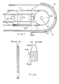
- FIG. 4 this shows one form of pallet or support means attached to a link 31 of the chain 11.
- the pallet is supported on a pair of support rails 32 located one each side of the chain 11.
- the pallet itself consists of a base portion 33 which has a pair of downturned cheeks 34 straddling an extension of the link 31 so as to locate the pallet and enable it to be driven by the chain.
- a security screw is shown at 36.
- the extension is securely attached to the chain 11 and loosely attached to the base portion 33.
- the cheeks 34 transmit drive from the chain link extension to the pallet, whilst allowing the chain to flex and oscillate.
- Guides 38 attached to the pallet base 33 rest against the side of the chain 11 to reduce snaking of the chain or pallet.
- the pallet rests on guide rails 32 which are aligned between sprocket centres, above the height of the chain on its run between sprockets, but the outer rail is positioned at the sprocket height adjacent the sprocket, the inner edge of a pallet resting on the sprocket as the pallet is driven therearound.
- the guide rails are curved downwardly when approaching a lower sprocket edge.
- FIG. 5 Also shown in Figure 5 is a sensing peg 37a fixed on the lower portion 33 of the pallet adjacent the chain 11, peg 33 is sensed by a sensor (not shown) positioned adjacent the edge of the sprocket 49 ( Figure 7) so as to send a control signal back to the drive mechanism control to enable accurate arrest of the pallets.
- a second peg 37b is removably affixed to the pallet and may be used to indicate the start or finish of a batch, this peg 37b is sensed by a sensor 59.
- a further boss or peg 38 may be provided to prevent slewing of the pallet in relation to the rail 32.
- the pallet is further shown as having a pair of support pillars 39 and an actual support surface 41 for the workpieces to be carried.
- the details of support mechanism for the workpieces are not shown, since these will be chosen for the components concerned.
- a contoured surface is provided on which the pieces may rest.
- the support surface may be readily replaceable on the pillars 39 to enable the magazine to be readily adapted for different types of component.
- Figure 8 shows a sprocket detail.
- the sprocket of the embodiment is of 23,5 cm (9) inch) outside diameter having teeth with 1,27 cm (z inch) pitch, to match a 1,27 cm (2 inch) chain.
- the teeth are tapered on each face at 12° to the plane of the sprocket, down to 3 mm at their outer edge. The taper extending beyond the teeth to the sprocket body which is 9 mm thick.
- Figures 9, 10 and 11 illustrate the arrangement of the chain 11 and supporting rails 32 intermediate the end sprockets of the front helix seen in Figure 1.
- Figure 9 is a plan view and shows end sprockets 53, 54.
- the chain 11 runs horizontally from sprockets 53 to 54 on the outer run 55, descending or ascending on the inner run 56.
- Inner support rails 32a, b, c, d are secured to uprights 57 of the housing 1 on lugs 58.
Landscapes
- Engineering & Computer Science (AREA)
- Mechanical Engineering (AREA)
- Feeding Of Workpieces (AREA)
- Thermally Insulated Containers For Foods (AREA)
- Devices For Use In Laboratory Experiments (AREA)
- Packages (AREA)
- Automatic Assembly (AREA)
Priority Applications (1)
| Application Number | Priority Date | Filing Date | Title |
|---|---|---|---|
| AT86900222T ATE37844T1 (de) | 1985-01-30 | 1985-12-24 | Lagernde foerdereinrichtung. |
Applications Claiming Priority (4)
| Application Number | Priority Date | Filing Date | Title |
|---|---|---|---|
| GB8502361 | 1985-01-30 | ||
| GB858502361A GB8502361D0 (en) | 1985-01-30 | 1985-01-30 | Storage magazine |
| GB8528578 | 1985-11-20 | ||
| GB858528578A GB8528578D0 (en) | 1985-01-30 | 1985-11-20 | Storage magazine |
Publications (2)
| Publication Number | Publication Date |
|---|---|
| EP0209537A1 EP0209537A1 (en) | 1987-01-28 |
| EP0209537B1 true EP0209537B1 (en) | 1988-10-12 |
Family
ID=26288732
Family Applications (1)
| Application Number | Title | Priority Date | Filing Date |
|---|---|---|---|
| EP86900222A Expired EP0209537B1 (en) | 1985-01-30 | 1985-12-24 | Storage conveyor |
Country Status (6)
| Country | Link |
|---|---|
| US (1) | US4848537A (da) |
| EP (1) | EP0209537B1 (da) |
| AU (1) | AU581053B2 (da) |
| DE (1) | DE3565505D1 (da) |
| DK (1) | DK155993C (da) |
| WO (1) | WO1986004564A1 (da) |
Families Citing this family (10)
| Publication number | Priority date | Publication date | Assignee | Title |
|---|---|---|---|---|
| US5125240A (en) * | 1989-08-04 | 1992-06-30 | Cryo-Cell International, Inc. | Storage apparatus, particularly with automatic insertion and retrieval |
| US5160567A (en) * | 1991-04-15 | 1992-11-03 | Allied-Signal Inc. | System and method for manufacturing copper clad glass epoxy laminates |
| IT1252106B (it) * | 1991-11-27 | 1995-06-02 | Tecno Pool Spa | Convogliatore a catene con dispositivo di traino migliorato |
| US5336032A (en) * | 1992-09-16 | 1994-08-09 | Eaton Corporation | Article handling system |
| DE102004022727B4 (de) * | 2004-05-07 | 2006-06-29 | Bijan Wolfgang Dipl.-Ing. Khanmoradi | Schichtungspalettierer zum Trocknen bzw. aufheizen von Gegenständen in einer Trocknungsanlage bzw. in einem Ofen |
| CN102596765A (zh) * | 2009-09-04 | 2012-07-18 | 莱特拉姆有限责任公司 | 螺旋型传送器系统和方法 |
| JP6111321B2 (ja) | 2012-04-16 | 2017-04-05 | ヴァーダニャン, アルメンVARDANYAN, Armen | 重力コンベヤー |
| CN202893626U (zh) * | 2012-09-25 | 2013-04-24 | 深圳富泰宏精密工业有限公司 | 烘烤传动系统 |
| IT202100016838A1 (it) * | 2021-06-28 | 2022-12-28 | S E M Servizi Editoriali Milano S P A | Torre di accumulo e trasporto a spirale per blocchi grafici |
| CN114291578A (zh) * | 2022-01-26 | 2022-04-08 | 滁州新彩家用玻璃有限公司 | 一种存储机器升降装置及生产线 |
Family Cites Families (15)
| Publication number | Priority date | Publication date | Assignee | Title |
|---|---|---|---|---|
| US1523971A (en) * | 1923-10-05 | 1925-01-20 | Carsten L Johnsen | Apparatus for treating briquettes |
| US3128875A (en) * | 1961-10-30 | 1964-04-14 | Reciprocating pusher-type conveyor | |
| US3517836A (en) * | 1968-06-27 | 1970-06-30 | Eltop Corp | Car tower-and means for storing automobiles in a spiral-shaped garage |
| US3599782A (en) * | 1968-11-15 | 1971-08-17 | Condeco Automation | Spiral storage feeder unit |
| AU469393B2 (en) * | 1971-12-01 | 1976-02-12 | Stewart Systems Inc. | Endless helical conveyer and belt |
| US3857476A (en) * | 1973-01-29 | 1974-12-31 | Theodore Equipment Corp | Helical endless-belt mechanisms for fuel or empty distray transporting and lifting |
| SE381241B (sv) * | 1973-03-07 | 1975-12-01 | Frigoscandia Contracting Ab | Transportanordning med ett endlost transportband vilket er anordnat att till en del av sin lengd folja en bana bestaende av ett antal over varandra belegna skruvformigt forlopande varv |
| NL7800640A (nl) * | 1977-03-08 | 1979-06-11 | Capelleveen Bv Geb | Transporteur, in het bijzonder voor een narijs- kast. |
| DE2717586C2 (de) * | 1977-04-20 | 1982-03-25 | Zahnradfabrik Friedrichshafen Ag, 7990 Friedrichshafen | Ortsbeweglicher Speicher zur Aufnahme und zum Transport von Werkstücken |
| DE7712802U1 (de) * | 1977-04-22 | 1977-09-22 | Alfred Lemmer, Werkzeug- Und Maschinenbau, 8000 Muenchen | Bestueckungstisch fuer leiterplatten |
| GB2050982A (en) * | 1979-05-22 | 1981-01-14 | Molins Ltd | Conveyor system for rod-like articles |
| JPS57194861A (en) * | 1981-05-25 | 1982-11-30 | Murata Mach Ltd | Automatic transfer system of workpiece in machine shop |
| SE434728B (sv) * | 1982-11-26 | 1984-08-13 | Frigoscandia Contracting Ab | Upplagsanordning for uppberande av ett antal det ena over det andra i stapel belegna skruvformigt forlopande varv av ett endlost transportband |
| US4588341A (en) * | 1983-07-08 | 1986-05-13 | Motoda Denshi Kogyo Kabushiki Kaisha | Article delivery apparatus |
| US4640657A (en) * | 1984-09-10 | 1987-02-03 | Moore Robert W | Carton loading method and system |
-
1985
- 1985-12-24 DE DE8686900222T patent/DE3565505D1/de not_active Expired
- 1985-12-24 EP EP86900222A patent/EP0209537B1/en not_active Expired
- 1985-12-24 WO PCT/GB1985/000602 patent/WO1986004564A1/en not_active Ceased
- 1985-12-24 US US07/240,404 patent/US4848537A/en not_active Expired - Fee Related
- 1985-12-24 AU AU53106/86A patent/AU581053B2/en not_active Ceased
-
1986
- 1986-09-25 DK DK458586A patent/DK155993C/da not_active IP Right Cessation
Also Published As
| Publication number | Publication date |
|---|---|
| DK155993B (da) | 1989-06-12 |
| DK155993C (da) | 1989-11-20 |
| WO1986004564A1 (en) | 1986-08-14 |
| DE3565505D1 (en) | 1988-11-17 |
| DK458586A (da) | 1986-09-25 |
| AU5310686A (en) | 1986-08-26 |
| DK458586D0 (da) | 1986-09-25 |
| AU581053B2 (en) | 1989-02-09 |
| US4848537A (en) | 1989-07-18 |
| EP0209537A1 (en) | 1987-01-28 |
Similar Documents
| Publication | Publication Date | Title |
|---|---|---|
| EP0209537B1 (en) | Storage conveyor | |
| CN101858387B (zh) | 汽车第一代轮毂轴承装配线 | |
| US4442935A (en) | Pallet magazine | |
| JPH0356306A (ja) | 帯状部材の取出し移送装置 | |
| CN201705819U (zh) | 汽车第一代轮毂轴承装配线 | |
| US3019925A (en) | Block handling apparatus | |
| GB1008247A (en) | Improvements in or relating to loading systems | |
| US4832175A (en) | Sorting and orienting structure and method | |
| US5829942A (en) | Apparatus for loading and unloading circuit boards along a conveyor system | |
| JP2983882B2 (ja) | パネル自動積込み装置 | |
| EP0268438B1 (en) | Improvements in collation assemblies | |
| SE436561B (sv) | Transportabelt arbetsstycksmagasin | |
| JP3807147B2 (ja) | 搬送設備 | |
| CN114455235A (zh) | 一种智能料仓 | |
| JPH1076426A (ja) | パイプねじ切り設備 | |
| JPH0751240Y2 (ja) | ワーク串差装置 | |
| JPS62501554A (ja) | 貯蔵コンベヤ | |
| US7114607B2 (en) | Method for operating a vertical accumulating conveyor system | |
| JP2528255B2 (ja) | ホイルへのタイヤ組付装置 | |
| JPS6222508Y2 (da) | ||
| JP2705872B2 (ja) | 混流生産システム | |
| JP2546728B2 (ja) | テーピング完了品の収納箱自動供給装置 | |
| JPH07179223A (ja) | 重箱状トレーへの製品積載装置 | |
| KR0164163B1 (ko) | Vtr용 하부드럼가공기의 미가공드럼공급 및 가공드럼반출용 보좌장치 | |
| KR200153802Y1 (ko) | 부품 공급장치 |
Legal Events
| Date | Code | Title | Description |
|---|---|---|---|
| PUAI | Public reference made under article 153(3) epc to a published international application that has entered the european phase |
Free format text: ORIGINAL CODE: 0009012 |
|
| 17P | Request for examination filed |
Effective date: 19861010 |
|
| AK | Designated contracting states |
Kind code of ref document: A1 Designated state(s): AT BE CH DE FR GB IT LI LU NL SE |
|
| 17Q | First examination report despatched |
Effective date: 19870922 |
|
| GRAA | (expected) grant |
Free format text: ORIGINAL CODE: 0009210 |
|
| AK | Designated contracting states |
Kind code of ref document: B1 Designated state(s): AT BE CH DE FR GB IT LI LU NL SE |
|
| REF | Corresponds to: |
Ref document number: 37844 Country of ref document: AT Date of ref document: 19881015 Kind code of ref document: T |
|
| REF | Corresponds to: |
Ref document number: 3565505 Country of ref document: DE Date of ref document: 19881117 |
|
| ITF | It: translation for a ep patent filed | ||
| ET | Fr: translation filed | ||
| PLBE | No opposition filed within time limit |
Free format text: ORIGINAL CODE: 0009261 |
|
| STAA | Information on the status of an ep patent application or granted ep patent |
Free format text: STATUS: NO OPPOSITION FILED WITHIN TIME LIMIT |
|
| 26N | No opposition filed | ||
| PGFP | Annual fee paid to national office [announced via postgrant information from national office to epo] |
Ref country code: SE Payment date: 19901228 Year of fee payment: 6 |
|
| ITTA | It: last paid annual fee | ||
| PGFP | Annual fee paid to national office [announced via postgrant information from national office to epo] |
Ref country code: NL Payment date: 19901231 Year of fee payment: 6 |
|
| PGFP | Annual fee paid to national office [announced via postgrant information from national office to epo] |
Ref country code: BE Payment date: 19910115 Year of fee payment: 6 |
|
| PGFP | Annual fee paid to national office [announced via postgrant information from national office to epo] |
Ref country code: LU Payment date: 19910128 Year of fee payment: 6 |
|
| EPTA | Lu: last paid annual fee | ||
| PG25 | Lapsed in a contracting state [announced via postgrant information from national office to epo] |
Ref country code: LU Free format text: LAPSE BECAUSE OF NON-PAYMENT OF DUE FEES Effective date: 19911224 |
|
| PG25 | Lapsed in a contracting state [announced via postgrant information from national office to epo] |
Ref country code: SE Effective date: 19911225 |
|
| PG25 | Lapsed in a contracting state [announced via postgrant information from national office to epo] |
Ref country code: BE Effective date: 19911231 |
|
| PGFP | Annual fee paid to national office [announced via postgrant information from national office to epo] |
Ref country code: FR Payment date: 19911231 Year of fee payment: 7 |
|
| PGFP | Annual fee paid to national office [announced via postgrant information from national office to epo] |
Ref country code: GB Payment date: 19920103 Year of fee payment: 7 |
|
| PGFP | Annual fee paid to national office [announced via postgrant information from national office to epo] |
Ref country code: AT Payment date: 19920109 Year of fee payment: 7 |
|
| PGFP | Annual fee paid to national office [announced via postgrant information from national office to epo] |
Ref country code: CH Payment date: 19920120 Year of fee payment: 7 |
|
| PGFP | Annual fee paid to national office [announced via postgrant information from national office to epo] |
Ref country code: DE Payment date: 19920131 Year of fee payment: 7 |
|
| BERE | Be: lapsed |
Owner name: ZANONI ROBERT BASIL Effective date: 19911231 Owner name: RICHARDS CLIVE DAVID GEORGE Effective date: 19911231 |
|
| PG25 | Lapsed in a contracting state [announced via postgrant information from national office to epo] |
Ref country code: NL Effective date: 19920701 |
|
| NLV4 | Nl: lapsed or anulled due to non-payment of the annual fee | ||
| PG25 | Lapsed in a contracting state [announced via postgrant information from national office to epo] |
Ref country code: GB Effective date: 19921224 Ref country code: AT Effective date: 19921224 |
|
| PG25 | Lapsed in a contracting state [announced via postgrant information from national office to epo] |
Ref country code: LI Effective date: 19921231 Ref country code: CH Effective date: 19921231 |
|
| GBPC | Gb: european patent ceased through non-payment of renewal fee |
Effective date: 19921224 |
|
| PG25 | Lapsed in a contracting state [announced via postgrant information from national office to epo] |
Ref country code: FR Effective date: 19930831 |
|
| REG | Reference to a national code |
Ref country code: CH Ref legal event code: PL |
|
| PG25 | Lapsed in a contracting state [announced via postgrant information from national office to epo] |
Ref country code: DE Effective date: 19930901 |
|
| REG | Reference to a national code |
Ref country code: FR Ref legal event code: ST |
|
| EUG | Se: european patent has lapsed |
Ref document number: 86900222.0 Effective date: 19920704 |