EP0208913A1 - Verfahren und Vorrichtung zum stirnseitigen Verschweissen von Bündeln von Formkörpern aus thermoplastischem Kunststoff unter Druckanwendung - Google Patents
Verfahren und Vorrichtung zum stirnseitigen Verschweissen von Bündeln von Formkörpern aus thermoplastischem Kunststoff unter Druckanwendung Download PDFInfo
- Publication number
- EP0208913A1 EP0208913A1 EP86107987A EP86107987A EP0208913A1 EP 0208913 A1 EP0208913 A1 EP 0208913A1 EP 86107987 A EP86107987 A EP 86107987A EP 86107987 A EP86107987 A EP 86107987A EP 0208913 A1 EP0208913 A1 EP 0208913A1
- Authority
- EP
- European Patent Office
- Prior art keywords
- grooves
- bundle
- end faces
- groove
- welding
- Prior art date
- Legal status (The legal status is an assumption and is not a legal conclusion. Google has not performed a legal analysis and makes no representation as to the accuracy of the status listed.)
- Granted
Links
- 238000003466 welding Methods 0.000 title claims abstract description 21
- 238000000034 method Methods 0.000 title claims description 16
- 229920001169 thermoplastic Polymers 0.000 title claims 2
- 238000003825 pressing Methods 0.000 title 1
- 239000004416 thermosoftening plastic Substances 0.000 title 1
- 239000004033 plastic Substances 0.000 claims abstract description 19
- 229920003023 plastic Polymers 0.000 claims abstract description 19
- 238000002844 melting Methods 0.000 claims abstract description 16
- 230000008018 melting Effects 0.000 claims abstract description 16
- 239000012815 thermoplastic material Substances 0.000 claims abstract description 6
- 239000000155 melt Substances 0.000 claims description 13
- 238000001816 cooling Methods 0.000 claims description 8
- 238000000465 moulding Methods 0.000 claims description 5
- 239000011810 insulating material Substances 0.000 claims description 3
- 230000000630 rising effect Effects 0.000 abstract 1
- 238000010438 heat treatment Methods 0.000 description 5
- 238000004519 manufacturing process Methods 0.000 description 4
- 239000002826 coolant Substances 0.000 description 3
- 239000004721 Polyphenylene oxide Substances 0.000 description 2
- 239000004793 Polystyrene Substances 0.000 description 2
- 150000001875 compounds Chemical class 0.000 description 2
- 230000000694 effects Effects 0.000 description 2
- 238000001125 extrusion Methods 0.000 description 2
- 239000000463 material Substances 0.000 description 2
- 229910052751 metal Inorganic materials 0.000 description 2
- 239000002184 metal Substances 0.000 description 2
- -1 polyethylene Polymers 0.000 description 2
- 229920006380 polyphenylene oxide Polymers 0.000 description 2
- 229910001369 Brass Inorganic materials 0.000 description 1
- 241000264877 Hippospongia communis Species 0.000 description 1
- 239000004696 Poly ether ether ketone Substances 0.000 description 1
- 239000004952 Polyamide Substances 0.000 description 1
- 239000004697 Polyetherimide Substances 0.000 description 1
- 239000004698 Polyethylene Substances 0.000 description 1
- 239000004743 Polypropylene Substances 0.000 description 1
- 229910000831 Steel Inorganic materials 0.000 description 1
- 229910052782 aluminium Inorganic materials 0.000 description 1
- XAGFODPZIPBFFR-UHFFFAOYSA-N aluminium Chemical compound [Al] XAGFODPZIPBFFR-UHFFFAOYSA-N 0.000 description 1
- 239000012080 ambient air Substances 0.000 description 1
- 239000010951 brass Substances 0.000 description 1
- 239000000919 ceramic Substances 0.000 description 1
- 230000001427 coherent effect Effects 0.000 description 1
- 239000004744 fabric Substances 0.000 description 1
- 239000000835 fiber Substances 0.000 description 1
- 230000009969 flowable effect Effects 0.000 description 1
- 239000011521 glass Substances 0.000 description 1
- 238000005338 heat storage Methods 0.000 description 1
- 238000009413 insulation Methods 0.000 description 1
- 239000002557 mineral fiber Substances 0.000 description 1
- 239000002991 molded plastic Substances 0.000 description 1
- 238000010137 moulding (plastic) Methods 0.000 description 1
- 229920000058 polyacrylate Polymers 0.000 description 1
- 229920002647 polyamide Polymers 0.000 description 1
- 229920000515 polycarbonate Polymers 0.000 description 1
- 239000004417 polycarbonate Substances 0.000 description 1
- 229920002530 polyetherether ketone Polymers 0.000 description 1
- 229920001601 polyetherimide Polymers 0.000 description 1
- 229920000573 polyethylene Polymers 0.000 description 1
- 229920001155 polypropylene Polymers 0.000 description 1
- 229920002223 polystyrene Polymers 0.000 description 1
- 229910000057 polysulfane Inorganic materials 0.000 description 1
- 229920000915 polyvinyl chloride Polymers 0.000 description 1
- 239000004800 polyvinyl chloride Substances 0.000 description 1
- 238000007789 sealing Methods 0.000 description 1
- 239000010959 steel Substances 0.000 description 1
Images

Classifications
-
- B—PERFORMING OPERATIONS; TRANSPORTING
- B29—WORKING OF PLASTICS; WORKING OF SUBSTANCES IN A PLASTIC STATE IN GENERAL
- B29C—SHAPING OR JOINING OF PLASTICS; SHAPING OF MATERIAL IN A PLASTIC STATE, NOT OTHERWISE PROVIDED FOR; AFTER-TREATMENT OF THE SHAPED PRODUCTS, e.g. REPAIRING
- B29C65/00—Joining or sealing of preformed parts, e.g. welding of plastics materials; Apparatus therefor
- B29C65/02—Joining or sealing of preformed parts, e.g. welding of plastics materials; Apparatus therefor by heating, with or without pressure
- B29C65/18—Joining or sealing of preformed parts, e.g. welding of plastics materials; Apparatus therefor by heating, with or without pressure using heated tools
-
- B—PERFORMING OPERATIONS; TRANSPORTING
- B29—WORKING OF PLASTICS; WORKING OF SUBSTANCES IN A PLASTIC STATE IN GENERAL
- B29C—SHAPING OR JOINING OF PLASTICS; SHAPING OF MATERIAL IN A PLASTIC STATE, NOT OTHERWISE PROVIDED FOR; AFTER-TREATMENT OF THE SHAPED PRODUCTS, e.g. REPAIRING
- B29C66/00—General aspects of processes or apparatus for joining preformed parts
- B29C66/01—General aspects dealing with the joint area or with the area to be joined
- B29C66/03—After-treatments in the joint area
- B29C66/034—Thermal after-treatments
- B29C66/0342—Cooling, e.g. transporting through welding and cooling zone
-
- B—PERFORMING OPERATIONS; TRANSPORTING
- B29—WORKING OF PLASTICS; WORKING OF SUBSTANCES IN A PLASTIC STATE IN GENERAL
- B29C—SHAPING OR JOINING OF PLASTICS; SHAPING OF MATERIAL IN A PLASTIC STATE, NOT OTHERWISE PROVIDED FOR; AFTER-TREATMENT OF THE SHAPED PRODUCTS, e.g. REPAIRING
- B29C66/00—General aspects of processes or apparatus for joining preformed parts
- B29C66/01—General aspects dealing with the joint area or with the area to be joined
- B29C66/05—Particular design of joint configurations
- B29C66/10—Particular design of joint configurations particular design of the joint cross-sections
- B29C66/13—Single flanged joints; Fin-type joints; Single hem joints; Edge joints; Interpenetrating fingered joints; Other specific particular designs of joint cross-sections not provided for in groups B29C66/11 - B29C66/12
- B29C66/137—Beaded-edge joints or bead seals
-
- B—PERFORMING OPERATIONS; TRANSPORTING
- B29—WORKING OF PLASTICS; WORKING OF SUBSTANCES IN A PLASTIC STATE IN GENERAL
- B29C—SHAPING OR JOINING OF PLASTICS; SHAPING OF MATERIAL IN A PLASTIC STATE, NOT OTHERWISE PROVIDED FOR; AFTER-TREATMENT OF THE SHAPED PRODUCTS, e.g. REPAIRING
- B29C66/00—General aspects of processes or apparatus for joining preformed parts
- B29C66/50—General aspects of joining tubular articles; General aspects of joining long products, i.e. bars or profiled elements; General aspects of joining single elements to tubular articles, hollow articles or bars; General aspects of joining several hollow-preforms to form hollow or tubular articles
- B29C66/51—Joining tubular articles, profiled elements or bars; Joining single elements to tubular articles, hollow articles or bars; Joining several hollow-preforms to form hollow or tubular articles
- B29C66/52—Joining tubular articles, bars or profiled elements
- B29C66/522—Joining tubular articles
- B29C66/5227—Joining tubular articles for forming multi-tubular articles by longitudinally joining elementary tubular articles wall-to-wall (e.g. joining the wall of a first tubular article to the wall of a second tubular article) or for forming multilayer tubular articles
-
- B—PERFORMING OPERATIONS; TRANSPORTING
- B29—WORKING OF PLASTICS; WORKING OF SUBSTANCES IN A PLASTIC STATE IN GENERAL
- B29C—SHAPING OR JOINING OF PLASTICS; SHAPING OF MATERIAL IN A PLASTIC STATE, NOT OTHERWISE PROVIDED FOR; AFTER-TREATMENT OF THE SHAPED PRODUCTS, e.g. REPAIRING
- B29C66/00—General aspects of processes or apparatus for joining preformed parts
- B29C66/70—General aspects of processes or apparatus for joining preformed parts characterised by the composition, physical properties or the structure of the material of the parts to be joined; Joining with non-plastics material
- B29C66/73—General aspects of processes or apparatus for joining preformed parts characterised by the composition, physical properties or the structure of the material of the parts to be joined; Joining with non-plastics material characterised by the intensive physical properties of the material of the parts to be joined, by the optical properties of the material of the parts to be joined, by the extensive physical properties of the parts to be joined, by the state of the material of the parts to be joined or by the material of the parts to be joined being a thermoplastic or a thermoset
- B29C66/735—General aspects of processes or apparatus for joining preformed parts characterised by the composition, physical properties or the structure of the material of the parts to be joined; Joining with non-plastics material characterised by the intensive physical properties of the material of the parts to be joined, by the optical properties of the material of the parts to be joined, by the extensive physical properties of the parts to be joined, by the state of the material of the parts to be joined or by the material of the parts to be joined being a thermoplastic or a thermoset characterised by the extensive physical properties of the parts to be joined
- B29C66/7352—Thickness, e.g. very thin
-
- B—PERFORMING OPERATIONS; TRANSPORTING
- B29—WORKING OF PLASTICS; WORKING OF SUBSTANCES IN A PLASTIC STATE IN GENERAL
- B29C—SHAPING OR JOINING OF PLASTICS; SHAPING OF MATERIAL IN A PLASTIC STATE, NOT OTHERWISE PROVIDED FOR; AFTER-TREATMENT OF THE SHAPED PRODUCTS, e.g. REPAIRING
- B29C66/00—General aspects of processes or apparatus for joining preformed parts
- B29C66/70—General aspects of processes or apparatus for joining preformed parts characterised by the composition, physical properties or the structure of the material of the parts to be joined; Joining with non-plastics material
- B29C66/73—General aspects of processes or apparatus for joining preformed parts characterised by the composition, physical properties or the structure of the material of the parts to be joined; Joining with non-plastics material characterised by the intensive physical properties of the material of the parts to be joined, by the optical properties of the material of the parts to be joined, by the extensive physical properties of the parts to be joined, by the state of the material of the parts to be joined or by the material of the parts to be joined being a thermoplastic or a thermoset
- B29C66/739—General aspects of processes or apparatus for joining preformed parts characterised by the composition, physical properties or the structure of the material of the parts to be joined; Joining with non-plastics material characterised by the intensive physical properties of the material of the parts to be joined, by the optical properties of the material of the parts to be joined, by the extensive physical properties of the parts to be joined, by the state of the material of the parts to be joined or by the material of the parts to be joined being a thermoplastic or a thermoset characterised by the material of the parts to be joined being a thermoplastic or a thermoset
- B29C66/7392—General aspects of processes or apparatus for joining preformed parts characterised by the composition, physical properties or the structure of the material of the parts to be joined; Joining with non-plastics material characterised by the intensive physical properties of the material of the parts to be joined, by the optical properties of the material of the parts to be joined, by the extensive physical properties of the parts to be joined, by the state of the material of the parts to be joined or by the material of the parts to be joined being a thermoplastic or a thermoset characterised by the material of the parts to be joined being a thermoplastic or a thermoset characterised by the material of at least one of the parts being a thermoplastic
- B29C66/73921—General aspects of processes or apparatus for joining preformed parts characterised by the composition, physical properties or the structure of the material of the parts to be joined; Joining with non-plastics material characterised by the intensive physical properties of the material of the parts to be joined, by the optical properties of the material of the parts to be joined, by the extensive physical properties of the parts to be joined, by the state of the material of the parts to be joined or by the material of the parts to be joined being a thermoplastic or a thermoset characterised by the material of the parts to be joined being a thermoplastic or a thermoset characterised by the material of at least one of the parts being a thermoplastic characterised by the materials of both parts being thermoplastics
-
- B—PERFORMING OPERATIONS; TRANSPORTING
- B29—WORKING OF PLASTICS; WORKING OF SUBSTANCES IN A PLASTIC STATE IN GENERAL
- B29C—SHAPING OR JOINING OF PLASTICS; SHAPING OF MATERIAL IN A PLASTIC STATE, NOT OTHERWISE PROVIDED FOR; AFTER-TREATMENT OF THE SHAPED PRODUCTS, e.g. REPAIRING
- B29C66/00—General aspects of processes or apparatus for joining preformed parts
- B29C66/80—General aspects of machine operations or constructions and parts thereof
- B29C66/81—General aspects of the pressing elements, i.e. the elements applying pressure on the parts to be joined in the area to be joined, e.g. the welding jaws or clamps
- B29C66/818—General aspects of the pressing elements, i.e. the elements applying pressure on the parts to be joined in the area to be joined, e.g. the welding jaws or clamps characterised by the cooling constructional aspects, or by the thermal or electrical insulating or conducting constructional aspects of the welding jaws or of the clamps ; comprising means for compensating for the thermal expansion of the welding jaws or of the clamps
- B29C66/8181—General aspects of the pressing elements, i.e. the elements applying pressure on the parts to be joined in the area to be joined, e.g. the welding jaws or clamps characterised by the cooling constructional aspects, or by the thermal or electrical insulating or conducting constructional aspects of the welding jaws or of the clamps ; comprising means for compensating for the thermal expansion of the welding jaws or of the clamps characterised by the cooling constructional aspects
- B29C66/81811—General aspects of the pressing elements, i.e. the elements applying pressure on the parts to be joined in the area to be joined, e.g. the welding jaws or clamps characterised by the cooling constructional aspects, or by the thermal or electrical insulating or conducting constructional aspects of the welding jaws or of the clamps ; comprising means for compensating for the thermal expansion of the welding jaws or of the clamps characterised by the cooling constructional aspects of the welding jaws
-
- B—PERFORMING OPERATIONS; TRANSPORTING
- B29—WORKING OF PLASTICS; WORKING OF SUBSTANCES IN A PLASTIC STATE IN GENERAL
- B29C—SHAPING OR JOINING OF PLASTICS; SHAPING OF MATERIAL IN A PLASTIC STATE, NOT OTHERWISE PROVIDED FOR; AFTER-TREATMENT OF THE SHAPED PRODUCTS, e.g. REPAIRING
- B29C66/00—General aspects of processes or apparatus for joining preformed parts
- B29C66/90—Measuring or controlling the joining process
- B29C66/91—Measuring or controlling the joining process by measuring or controlling the temperature, the heat or the thermal flux
- B29C66/914—Measuring or controlling the joining process by measuring or controlling the temperature, the heat or the thermal flux by controlling or regulating the temperature, the heat or the thermal flux
- B29C66/9141—Measuring or controlling the joining process by measuring or controlling the temperature, the heat or the thermal flux by controlling or regulating the temperature, the heat or the thermal flux by controlling or regulating the temperature
- B29C66/91421—Measuring or controlling the joining process by measuring or controlling the temperature, the heat or the thermal flux by controlling or regulating the temperature, the heat or the thermal flux by controlling or regulating the temperature of the joining tools
-
- B—PERFORMING OPERATIONS; TRANSPORTING
- B29—WORKING OF PLASTICS; WORKING OF SUBSTANCES IN A PLASTIC STATE IN GENERAL
- B29C—SHAPING OR JOINING OF PLASTICS; SHAPING OF MATERIAL IN A PLASTIC STATE, NOT OTHERWISE PROVIDED FOR; AFTER-TREATMENT OF THE SHAPED PRODUCTS, e.g. REPAIRING
- B29C66/00—General aspects of processes or apparatus for joining preformed parts
- B29C66/90—Measuring or controlling the joining process
- B29C66/91—Measuring or controlling the joining process by measuring or controlling the temperature, the heat or the thermal flux
- B29C66/914—Measuring or controlling the joining process by measuring or controlling the temperature, the heat or the thermal flux by controlling or regulating the temperature, the heat or the thermal flux
- B29C66/9141—Measuring or controlling the joining process by measuring or controlling the temperature, the heat or the thermal flux by controlling or regulating the temperature, the heat or the thermal flux by controlling or regulating the temperature
- B29C66/91441—Measuring or controlling the joining process by measuring or controlling the temperature, the heat or the thermal flux by controlling or regulating the temperature, the heat or the thermal flux by controlling or regulating the temperature the temperature being non-constant over time
- B29C66/91443—Measuring or controlling the joining process by measuring or controlling the temperature, the heat or the thermal flux by controlling or regulating the temperature, the heat or the thermal flux by controlling or regulating the temperature the temperature being non-constant over time following a temperature-time profile
- B29C66/91445—Measuring or controlling the joining process by measuring or controlling the temperature, the heat or the thermal flux by controlling or regulating the temperature, the heat or the thermal flux by controlling or regulating the temperature the temperature being non-constant over time following a temperature-time profile by steps
-
- B—PERFORMING OPERATIONS; TRANSPORTING
- B29—WORKING OF PLASTICS; WORKING OF SUBSTANCES IN A PLASTIC STATE IN GENERAL
- B29C—SHAPING OR JOINING OF PLASTICS; SHAPING OF MATERIAL IN A PLASTIC STATE, NOT OTHERWISE PROVIDED FOR; AFTER-TREATMENT OF THE SHAPED PRODUCTS, e.g. REPAIRING
- B29C66/00—General aspects of processes or apparatus for joining preformed parts
- B29C66/90—Measuring or controlling the joining process
- B29C66/91—Measuring or controlling the joining process by measuring or controlling the temperature, the heat or the thermal flux
- B29C66/919—Measuring or controlling the joining process by measuring or controlling the temperature, the heat or the thermal flux characterised by specific temperature, heat or thermal flux values or ranges
-
- B—PERFORMING OPERATIONS; TRANSPORTING
- B29—WORKING OF PLASTICS; WORKING OF SUBSTANCES IN A PLASTIC STATE IN GENERAL
- B29C—SHAPING OR JOINING OF PLASTICS; SHAPING OF MATERIAL IN A PLASTIC STATE, NOT OTHERWISE PROVIDED FOR; AFTER-TREATMENT OF THE SHAPED PRODUCTS, e.g. REPAIRING
- B29C66/00—General aspects of processes or apparatus for joining preformed parts
- B29C66/90—Measuring or controlling the joining process
- B29C66/91—Measuring or controlling the joining process by measuring or controlling the temperature, the heat or the thermal flux
- B29C66/919—Measuring or controlling the joining process by measuring or controlling the temperature, the heat or the thermal flux characterised by specific temperature, heat or thermal flux values or ranges
- B29C66/9192—Measuring or controlling the joining process by measuring or controlling the temperature, the heat or the thermal flux characterised by specific temperature, heat or thermal flux values or ranges in explicit relation to another variable, e.g. temperature diagrams
- B29C66/91921—Measuring or controlling the joining process by measuring or controlling the temperature, the heat or the thermal flux characterised by specific temperature, heat or thermal flux values or ranges in explicit relation to another variable, e.g. temperature diagrams in explicit relation to another temperature, e.g. to the softening temperature or softening point, to the thermal degradation temperature or to the ambient temperature
-
- B—PERFORMING OPERATIONS; TRANSPORTING
- B29—WORKING OF PLASTICS; WORKING OF SUBSTANCES IN A PLASTIC STATE IN GENERAL
- B29C—SHAPING OR JOINING OF PLASTICS; SHAPING OF MATERIAL IN A PLASTIC STATE, NOT OTHERWISE PROVIDED FOR; AFTER-TREATMENT OF THE SHAPED PRODUCTS, e.g. REPAIRING
- B29C66/00—General aspects of processes or apparatus for joining preformed parts
- B29C66/90—Measuring or controlling the joining process
- B29C66/91—Measuring or controlling the joining process by measuring or controlling the temperature, the heat or the thermal flux
- B29C66/919—Measuring or controlling the joining process by measuring or controlling the temperature, the heat or the thermal flux characterised by specific temperature, heat or thermal flux values or ranges
- B29C66/9192—Measuring or controlling the joining process by measuring or controlling the temperature, the heat or the thermal flux characterised by specific temperature, heat or thermal flux values or ranges in explicit relation to another variable, e.g. temperature diagrams
- B29C66/91921—Measuring or controlling the joining process by measuring or controlling the temperature, the heat or the thermal flux characterised by specific temperature, heat or thermal flux values or ranges in explicit relation to another variable, e.g. temperature diagrams in explicit relation to another temperature, e.g. to the softening temperature or softening point, to the thermal degradation temperature or to the ambient temperature
- B29C66/91931—Measuring or controlling the joining process by measuring or controlling the temperature, the heat or the thermal flux characterised by specific temperature, heat or thermal flux values or ranges in explicit relation to another variable, e.g. temperature diagrams in explicit relation to another temperature, e.g. to the softening temperature or softening point, to the thermal degradation temperature or to the ambient temperature in explicit relation to the fusion temperature or melting point of the material of one of the parts to be joined
-
- B—PERFORMING OPERATIONS; TRANSPORTING
- B29—WORKING OF PLASTICS; WORKING OF SUBSTANCES IN A PLASTIC STATE IN GENERAL
- B29C—SHAPING OR JOINING OF PLASTICS; SHAPING OF MATERIAL IN A PLASTIC STATE, NOT OTHERWISE PROVIDED FOR; AFTER-TREATMENT OF THE SHAPED PRODUCTS, e.g. REPAIRING
- B29C66/00—General aspects of processes or apparatus for joining preformed parts
- B29C66/90—Measuring or controlling the joining process
- B29C66/91—Measuring or controlling the joining process by measuring or controlling the temperature, the heat or the thermal flux
- B29C66/919—Measuring or controlling the joining process by measuring or controlling the temperature, the heat or the thermal flux characterised by specific temperature, heat or thermal flux values or ranges
- B29C66/9192—Measuring or controlling the joining process by measuring or controlling the temperature, the heat or the thermal flux characterised by specific temperature, heat or thermal flux values or ranges in explicit relation to another variable, e.g. temperature diagrams
- B29C66/91921—Measuring or controlling the joining process by measuring or controlling the temperature, the heat or the thermal flux characterised by specific temperature, heat or thermal flux values or ranges in explicit relation to another variable, e.g. temperature diagrams in explicit relation to another temperature, e.g. to the softening temperature or softening point, to the thermal degradation temperature or to the ambient temperature
- B29C66/91931—Measuring or controlling the joining process by measuring or controlling the temperature, the heat or the thermal flux characterised by specific temperature, heat or thermal flux values or ranges in explicit relation to another variable, e.g. temperature diagrams in explicit relation to another temperature, e.g. to the softening temperature or softening point, to the thermal degradation temperature or to the ambient temperature in explicit relation to the fusion temperature or melting point of the material of one of the parts to be joined
- B29C66/91933—Measuring or controlling the joining process by measuring or controlling the temperature, the heat or the thermal flux characterised by specific temperature, heat or thermal flux values or ranges in explicit relation to another variable, e.g. temperature diagrams in explicit relation to another temperature, e.g. to the softening temperature or softening point, to the thermal degradation temperature or to the ambient temperature in explicit relation to the fusion temperature or melting point of the material of one of the parts to be joined higher than said fusion temperature
-
- B—PERFORMING OPERATIONS; TRANSPORTING
- B29—WORKING OF PLASTICS; WORKING OF SUBSTANCES IN A PLASTIC STATE IN GENERAL
- B29C—SHAPING OR JOINING OF PLASTICS; SHAPING OF MATERIAL IN A PLASTIC STATE, NOT OTHERWISE PROVIDED FOR; AFTER-TREATMENT OF THE SHAPED PRODUCTS, e.g. REPAIRING
- B29C66/00—General aspects of processes or apparatus for joining preformed parts
- B29C66/90—Measuring or controlling the joining process
- B29C66/91—Measuring or controlling the joining process by measuring or controlling the temperature, the heat or the thermal flux
- B29C66/919—Measuring or controlling the joining process by measuring or controlling the temperature, the heat or the thermal flux characterised by specific temperature, heat or thermal flux values or ranges
- B29C66/9192—Measuring or controlling the joining process by measuring or controlling the temperature, the heat or the thermal flux characterised by specific temperature, heat or thermal flux values or ranges in explicit relation to another variable, e.g. temperature diagrams
- B29C66/91921—Measuring or controlling the joining process by measuring or controlling the temperature, the heat or the thermal flux characterised by specific temperature, heat or thermal flux values or ranges in explicit relation to another variable, e.g. temperature diagrams in explicit relation to another temperature, e.g. to the softening temperature or softening point, to the thermal degradation temperature or to the ambient temperature
- B29C66/91931—Measuring or controlling the joining process by measuring or controlling the temperature, the heat or the thermal flux characterised by specific temperature, heat or thermal flux values or ranges in explicit relation to another variable, e.g. temperature diagrams in explicit relation to another temperature, e.g. to the softening temperature or softening point, to the thermal degradation temperature or to the ambient temperature in explicit relation to the fusion temperature or melting point of the material of one of the parts to be joined
- B29C66/91935—Measuring or controlling the joining process by measuring or controlling the temperature, the heat or the thermal flux characterised by specific temperature, heat or thermal flux values or ranges in explicit relation to another variable, e.g. temperature diagrams in explicit relation to another temperature, e.g. to the softening temperature or softening point, to the thermal degradation temperature or to the ambient temperature in explicit relation to the fusion temperature or melting point of the material of one of the parts to be joined lower than said fusion temperature
-
- F—MECHANICAL ENGINEERING; LIGHTING; HEATING; WEAPONS; BLASTING
- F28—HEAT EXCHANGE IN GENERAL
- F28F—DETAILS OF HEAT-EXCHANGE AND HEAT-TRANSFER APPARATUS, OF GENERAL APPLICATION
- F28F1/00—Tubular elements; Assemblies of tubular elements
- F28F1/006—Tubular elements; Assemblies of tubular elements with variable shape, e.g. with modified tube ends, with different geometrical features
-
- F—MECHANICAL ENGINEERING; LIGHTING; HEATING; WEAPONS; BLASTING
- F28—HEAT EXCHANGE IN GENERAL
- F28F—DETAILS OF HEAT-EXCHANGE AND HEAT-TRANSFER APPARATUS, OF GENERAL APPLICATION
- F28F21/00—Constructions of heat-exchange apparatus characterised by the selection of particular materials
- F28F21/06—Constructions of heat-exchange apparatus characterised by the selection of particular materials of plastics material
- F28F21/062—Constructions of heat-exchange apparatus characterised by the selection of particular materials of plastics material the heat-exchange apparatus employing tubular conduits
-
- B—PERFORMING OPERATIONS; TRANSPORTING
- B29—WORKING OF PLASTICS; WORKING OF SUBSTANCES IN A PLASTIC STATE IN GENERAL
- B29C—SHAPING OR JOINING OF PLASTICS; SHAPING OF MATERIAL IN A PLASTIC STATE, NOT OTHERWISE PROVIDED FOR; AFTER-TREATMENT OF THE SHAPED PRODUCTS, e.g. REPAIRING
- B29C65/00—Joining or sealing of preformed parts, e.g. welding of plastics materials; Apparatus therefor
- B29C65/02—Joining or sealing of preformed parts, e.g. welding of plastics materials; Apparatus therefor by heating, with or without pressure
- B29C65/18—Joining or sealing of preformed parts, e.g. welding of plastics materials; Apparatus therefor by heating, with or without pressure using heated tools
- B29C65/24—Joining or sealing of preformed parts, e.g. welding of plastics materials; Apparatus therefor by heating, with or without pressure using heated tools characterised by the means for heating the tool
- B29C65/30—Electrical means
- B29C65/305—Electrical means involving the use of cartridge heaters
-
- B—PERFORMING OPERATIONS; TRANSPORTING
- B29—WORKING OF PLASTICS; WORKING OF SUBSTANCES IN A PLASTIC STATE IN GENERAL
- B29C—SHAPING OR JOINING OF PLASTICS; SHAPING OF MATERIAL IN A PLASTIC STATE, NOT OTHERWISE PROVIDED FOR; AFTER-TREATMENT OF THE SHAPED PRODUCTS, e.g. REPAIRING
- B29C66/00—General aspects of processes or apparatus for joining preformed parts
- B29C66/70—General aspects of processes or apparatus for joining preformed parts characterised by the composition, physical properties or the structure of the material of the parts to be joined; Joining with non-plastics material
- B29C66/71—General aspects of processes or apparatus for joining preformed parts characterised by the composition, physical properties or the structure of the material of the parts to be joined; Joining with non-plastics material characterised by the composition of the plastics material of the parts to be joined
-
- B—PERFORMING OPERATIONS; TRANSPORTING
- B29—WORKING OF PLASTICS; WORKING OF SUBSTANCES IN A PLASTIC STATE IN GENERAL
- B29C—SHAPING OR JOINING OF PLASTICS; SHAPING OF MATERIAL IN A PLASTIC STATE, NOT OTHERWISE PROVIDED FOR; AFTER-TREATMENT OF THE SHAPED PRODUCTS, e.g. REPAIRING
- B29C66/00—General aspects of processes or apparatus for joining preformed parts
- B29C66/90—Measuring or controlling the joining process
- B29C66/92—Measuring or controlling the joining process by measuring or controlling the pressure, the force, the mechanical power or the displacement of the joining tools
- B29C66/929—Measuring or controlling the joining process by measuring or controlling the pressure, the force, the mechanical power or the displacement of the joining tools characterized by specific pressure, force, mechanical power or displacement values or ranges
-
- B—PERFORMING OPERATIONS; TRANSPORTING
- B29—WORKING OF PLASTICS; WORKING OF SUBSTANCES IN A PLASTIC STATE IN GENERAL
- B29K—INDEXING SCHEME ASSOCIATED WITH SUBCLASSES B29B, B29C OR B29D, RELATING TO MOULDING MATERIALS OR TO MATERIALS FOR MOULDS, REINFORCEMENTS, FILLERS OR PREFORMED PARTS, e.g. INSERTS
- B29K2995/00—Properties of moulding materials, reinforcements, fillers, preformed parts or moulds
- B29K2995/0037—Other properties
- B29K2995/0072—Roughness, e.g. anti-slip
- B29K2995/0073—Roughness, e.g. anti-slip smooth
-
- B—PERFORMING OPERATIONS; TRANSPORTING
- B29—WORKING OF PLASTICS; WORKING OF SUBSTANCES IN A PLASTIC STATE IN GENERAL
- B29L—INDEXING SCHEME ASSOCIATED WITH SUBCLASS B29C, RELATING TO PARTICULAR ARTICLES
- B29L2031/00—Other particular articles
- B29L2031/18—Heat-exchangers or parts thereof
-
- B—PERFORMING OPERATIONS; TRANSPORTING
- B29—WORKING OF PLASTICS; WORKING OF SUBSTANCES IN A PLASTIC STATE IN GENERAL
- B29L—INDEXING SCHEME ASSOCIATED WITH SUBCLASS B29C, RELATING TO PARTICULAR ARTICLES
- B29L2031/00—Other particular articles
- B29L2031/60—Multitubular or multicompartmented articles, e.g. honeycomb
- B29L2031/601—Multi-tubular articles, i.e. composed of a plurality of tubes
-
- Y—GENERAL TAGGING OF NEW TECHNOLOGICAL DEVELOPMENTS; GENERAL TAGGING OF CROSS-SECTIONAL TECHNOLOGIES SPANNING OVER SEVERAL SECTIONS OF THE IPC; TECHNICAL SUBJECTS COVERED BY FORMER USPC CROSS-REFERENCE ART COLLECTIONS [XRACs] AND DIGESTS
- Y10—TECHNICAL SUBJECTS COVERED BY FORMER USPC
- Y10T—TECHNICAL SUBJECTS COVERED BY FORMER US CLASSIFICATION
- Y10T428/00—Stock material or miscellaneous articles
- Y10T428/24—Structurally defined web or sheet [e.g., overall dimension, etc.]
- Y10T428/24149—Honeycomb-like
- Y10T428/24165—Hexagonally shaped cavities
Definitions
- the invention relates to a method and a device for the end face welding of a bundle of molded articles made of thermoplastic material.
- heat exchangers are welded from a bundle of extruded hollow chamber plates made of plastic lying on the end face to form a coherent bundle by means of heating tapes placed between the hollow chambers. This method of operation is used for some hollow profile bodies, e.g. Pipes, difficult to use.
- DE-PS 2 603 615 describes a device for welding a tube bundle made of thermoplastic material, in which the bundle is clamped between two heated plates pressed against the end faces, which have annular grooves corresponding to the tubes. The pipe ends protruding into the grooves are melted and welded together. However, only a low pressure can be used, because otherwise the melt would emerge from the grooves, the width of which is greater than the wall thickness of the pipes. However, the low applicable pressure does not guarantee perfect welding of the pipe ends.
- the invention has for its object to reliably and properly weld bundles of molded articles made of thermoplastic material with any cross-sections, the end faces of which lie in a surface and the end faces of which are flat against one another, by means of an improved method or an improved device.
- the invention is based on the known device with a plate which can be pressed onto the end face of the bundle and which has heatable grooves which are arranged in accordance with the cross section of the bundle and have a greater width than the thickness of the corresponding ends of the shaped bodies which lie flat against one another.
- the pressable plate is constructed so that the bottom of the grooves can be heated to or above the melting temperature of the plastic, but the entrance of the groove is thermally insulated from the bottom area in such a way that it remains below the melting temperature of the plastic during operation. If the heat flow to the entrance area is so high that the melting temperature would be exceeded, a cooling device must be installed there. It is important that the entrance area is thermally insulated on all sides and can be cooled if necessary, ie at any point where plastic bodies are in the Protrude groove. This also applies to lateral openings of the grooves if the plate is smaller than the end face of the bundle of shaped bodies.
- the heated space of the grooves is filled with the melt and the melt into the gap between the wall of the groove inlet under the pressure of the ends of the shaped bodies projecting into the grooves. protruding part of the molded body, where it is cooled below the melting temperature and solidifies.
- This closure prevents the melt from softening out of the groove on all sides. It is therefore possible according to the invention to apply a pressure in which the heated space of the groove is completely filled with the plastic melt and in which the adjacent ends of the hollow profile body reliably and perfectly weld together to form a seam shape defined by the shape of the groove.
- the thermal insulation or cooling of the entrance area not only has the effect that the melt emerging from the bottom area solidifies there, but also that the ends of the hollow profile bodies do not melt in this part of the groove and therefore transmit the pressure into the bottom area of the groove capital.
- the method and the device of the invention serve for the production of welded bundles of shaped bodies which are suitable for a wide variety of purposes.
- a preferred application is the production of heat exchangers or heat stores.
- heat is absorbed by a hot medium flowing through and released to a cold medium in a subsequent operating phase.
- it is sufficient if the front side of the welded bundle can be flowed through.
- at least two separate duct systems must be available, one of which is accessible from the end faces and the other can be flowed through from the sides of the bundle.
- Typical heat storage or heat exchanger bodies have cross-sectional areas between 0.1 and 6 square meters and a length between 0.5 and 10 m.
- the invention also allows the production of even larger or smaller bundles.
- the invention is not limited to the welding of molded plastic bodies of a certain shape. They can have any shape as long as they allow two or more identical or differently shaped bodies to be joined together so that their edges lie flat on one another at least in some areas and form a common edge, which is referred to here as the "front side". Thin-walled moldings are preferably welded together.
- the one to be welded according to the invention in one operation The end face must lie in a surface that is preferably, but not necessarily, a plane.
- the surface can also be curved, arched or kinked.
- a bundle can be welded to one or more end faces. There are preferably two end faces opposite each other, which can be welded simultaneously with separate tools or one after the other.
- shaped bodies those with a constant profile are preferred at least in the major part of their longitudinal extent, and among these in turn those with one or more hollow chambers are preferred.
- Such moldings can be produced by extrusion and have end faces lying transversely to the direction of extrusion. All of the hollow profile bodies combined in a bundle preferably have the same length, so that a bundle with two flat end faces can be produced therefrom. Both end faces are preferably welded - as a rule at the same time - in the sense of the invention.
- hollow profile bodies When welding hollow profile bodies, it is desirable that only the hollow chambers remain open on the end faces and that no gaps between the individual hollow profile bodies are accessible from the end face. In these cases, it is necessary for the hollow profile bodies to lie flat against one another over their entire circumference at the front ends, provided that this is not in the outside of the bundle.
- the hollow profile ends can e.g. have the shape of a regular hexagon and be laid together like honeycombs. Hollow chamber panels made of two smooth parallel outer walls and connecting webs can be folded into a stack and welded on the end face according to the invention. In principle, all hollow profile bodies are suitable for such bundles, the profile cross-sectional areas of which can be joined together to form a closed surface.
- the cross section can have a different shape in the rest of the area distant from the end faces.
- tubes with a predominantly circular cross section and ends widened to a regular hexagon cross section can be used.
- the area in which the ends lie flat against one another only needs to be a little longer than the depth of the groove.
- Tubes with widened end pieces are expediently used for the production of tube bundle heat exchangers, as a result of which a flowable space remains open when they are joined to form a bundle between the unexpanded tube sections.
- thermoplastic materials come in at room temperature stiff and melting in the range between about 50 and 300 ° C Molding compounds into consideration. However, the invention is not limited to these temperature limits.
- the "melting temperature” is the temperature at which the plastic is plastically softened to such an extent that two separately produced melts flow together at least under pressure to form a seamlessly solidifying body. If melts of different plastics meet this requirement, plastic bodies made of these different plastics can also be welded into a bundle. Below the melting temperature, the plastics are in a thermoelastically softened state. Only when they cool below the softening temperature do they change to the hard state (glass state).
- plastics examples include polyethylene, polypropylene, polystyrene, polyvinyl chloride, polyacrylates, polycarbonate, polysulfanes, polyphenylene oxide, polyetherimide, polyether ether ketones or polyamides.
- 1 represents the plate with the groove 2 that can be pressed onto the hollow profile bundle.
- the bottom 3 of the groove can be heated to the melting temperature of the plastic or above by heating elements 4 or channels 4 through which a heating medium can flow.
- the inlet 5 of the groove can be cooled via a coolant channel 6.
- the supply lines for the heating or cooling elements 4 and 6 are not shown for reasons of clarity.
- the part 8 of the plate 2 which can be heated via the melting temperature preferably consists of metal, such as steel, aluminum or brass.
- the thermally insulated part 9 can also consist of metal. In between, there is expediently a layer 10 of heat-insulating material, e.g. a mineral fiber fleece or a heat-resistant plastic molding compound, optionally reinforced with fibers or fabrics, or a ceramic body. Sometimes it is sufficient if the thermally insulated part 9 itself consists of such a thermally insulating material.
- the bottom 3 of the groove is heated to 240 to 280 ° C. and the inlet 5 is kept at a temperature below 130 ° C. by cooling. It is generally preferred to keep the entrance area at a temperature below the softening temperature of the plastic.
- the pressure generated in the heated groove area by the press-in force is, for example, between 0.6 and 100 N / cm 2 . As a result, melt currents 13 flow from the bottom 3 of the groove into the inlet gap, where they come into contact with the cool Solidify wall 5 of the entrance.
- the heating can be switched off and the material in the groove can be cooled below the melting temperature, preferably below the softening temperature. If this does not happen quickly enough due to heat being released into the ambient air, cooling can be supported by a cooling system.
- a coolant can flow through the channels 4 or special coolant channels 14. After cooling, the weld can be removed from the groove. This is facilitated by a weakly wedge-shaped cross section of the groove.
- the tube bundle shown in FIG. 2 is composed of three circular tubes 20 with end pieces 21 widened in the shape of a hexagon.
- the end pieces lie flat against one another in the areas 22.
- the wall thickness 23 in this area is, for example, 1 to 8 mm, in the areas 24 half, that is 0.5 to 4 mm.
- the tube bundle shown in FIG. 2 is sunk into the plate 1 according to FIG. 3.
- the grooves 2 provided for welding the end pieces have a greater width in the input region 26 than the wall thickness 23, but can converge towards the bottom of the groove to a width corresponding to the wall thickness 23 or even less.
- the edge groove 27 only serves to melt the outer wall onto the same plane 28 as the areas to be welded.
- a plate 1 is sufficient to carry out the method. However, it is preferred to simultaneously ver the two end faces of a bundle by means of two plates 1 welding. These are moved parallel to each other during the welding process by the amount that the end pieces are sunk into the grooves. For this purpose, a pushing device is expediently used, which moves at least one of the plates and generates the pressure required for welding.
- the plates are arranged in parallel on a support frame, which preferably also carries a holding device for receiving the bundle before and after the welding process.
Landscapes
- Engineering & Computer Science (AREA)
- Physics & Mathematics (AREA)
- Mechanical Engineering (AREA)
- Thermal Sciences (AREA)
- High Energy & Nuclear Physics (AREA)
- Plasma & Fusion (AREA)
- General Engineering & Computer Science (AREA)
- Geometry (AREA)
- Lining Or Joining Of Plastics Or The Like (AREA)
Abstract
Description
- Die Erfindung betrifft ein Verfahren und eine Vorrichtung zum stirnseitigen Verschweißen eines Bündels von Formkörpern aus thermoplastischem Kunststoff.
- Nach dem deutschen Gebrauchsmuster 84 29 157 werden Wärmetauscher aus einem Bündel aufeinanderliegender extrudierter Hohlkammerplatten aus Kunststoff stirnseitig mittels zwischen die Hohlkammern gelegten Heizbändem zu einem zusammenhängenden Bündel verschweißt. Diese Arbeitsweise ist bei manchen Hohlprofilkörpern, wie z.B. Rohren, schwer anwendbar.
- In der DE-PS 2 603 615 wird eine Vorrichtung zum Verschweißen eines Rohrbündels aus thermoplastischem Kunststoff beschrieben, in der das Bündel zwischen zwei an die Stirnseiten angedrückte beheizte Platten, die den Rohren entsprechend ringförmige Nuten aufweisen, eingespannt wird. Die in die Nuten hineinragenden Rohrenden werden aufgeschmolzen und miteinander verschweißt. Dabei kann jedoch nur ein geringer Druck angewendet werden, weil sonst die Schmelze aus den Nuten, deren Weite größer als die Wandstärke der Rohre ist, heraustreten würde. Der geringe anwendbare Druck gewährleistet jedoch keine einwandfreie Verschweißung der Rohrenden.
- Der Erfindung liegt die Aufgabe zugrunde, Bündel von Formkörpern aus thermoplastischem Kunststoff mit beliebigen Querschnitten, deren Stirnseiten in einer Fläche liegen und deren stirnseitige Ehden flächig aneinander liegen, durch ein verbessertes Verfahren bzw. eine verbesserte Vorrichtung zuverlässig und einwandfrei zu verschweißen.
- Zur Lösung dieser Aufgabe geht die Erfindung von der bekannten Vorrichtung mit einer an die Stirnseite des Bündels andrückbaren Platte mit beheizbaren Nuten aus, die entsprechend dem Querschnitt des Bündels angeordnet sind und eine größere Weite als die Dicke der entsprechenden, flächig aneinanderliegenden Enden der Formkörper haben. Bei Betätigung der Vorrichtung werden die flächig aneinanderliegenden Enden in die beheizten Nuten unter Druck eingesenkt, der Kunststoff geschmolzen und nach dem Zusammenfließen der aus den aneinanderliegenden Enden entstandenen Schmelzen innerhalb der Nut unter die Schmelztemperatur gekühlt.
- Erfindungsgemäß ist die andrückbare Platte so aufgebaut, daß der Boden der Nuten auf oder über die Schmelztemperatur des Kunststoffes heizbar ist, aber der Eingang der Nut gegen den Bodenbereich derart thermisch isoliert ist, daß er im Betrieb unterhalb der Schmelztemperatur des Kunststoffes bleibt. Wenn der Wärmezufluß zum Eingangsbereich so hoch ist, daß dort die Schmelztemperatur überschritten würde, so ist dort eine Kühlvorrichtung anzubringen. Wichtig ist, daß der Eingangsbereich allseitig thermisch isoliert und gegebenenfalls kühlbar ist, d.h. an jeder Stelle, wo Kunststoffkörper in die Nut hineinragen. Dies gilt auch für seitliche Öffnungen der Nuten, wenn die Platte kleiner als die Stirnseite des Formkörperbündels ist. Bei dem erfindungsgemäßen Schweißverfahren wird unter dem Druck der in die Nuten hineinragenden Enden der Formkörper der beheizte Raum der Nuten mit der Schmelze gefüllt und die Schmelze in den Spalt zwischen der Wandung des Nuteinganges . hineinragenden Teil des Formkörpers getrieben, wo sie unter die Schmelztemperatur gekühlt wird und erstarrt.
- Die in den Eingangsspalt der Nut getriebene und dort erstarrende Schmelze bildet einen dichtenden Verschluß des beheizten Nutraunes. Dieser Verschluß verhindert allseitig das Ehtweichen der Schmelze aus der Nut. Es ist daher erfindungsgemäß möglich, einen Druck anzuwenden, bei dem der beheizte Raum der Nut vollständig mit der Kunststoffschmelze gefüllt wird und in welchem die aneinanderliegenden Ehden der Hohlprofilkörper zuverlässig und einwandfrei unter Ausbildung einer durch die Gestalt der Nut definierten Nahtform miteinander verschweißen. Die thermische Isolierung bzw. die Kühlung des Eingangsbereiches hat nicht nur die Wirkung, daß die aus dem Bodenbereich austretende Schmelze dort erstarrt, sondern auch daß die Enden der Hohlprofilkörper in diesem Teil der Nut nicht schmelzen und daher den Druck in den Bodenbereich der Nut zu übertragen vermögen.
- Das Verfahren und die Vorrichtung der Erfindung dienen zur Herstellung von verschweißten Bündeln von Formkörpem, die für die verschiedensten Zwecke geeignet sind. Eine bevorzugte Anwendung ist die Herstellung von Wärmetauschern oder Wärmespeichern. Bei der Anwendung der Bündel als Wärmespeicher wird Wärme von einem durchströmenden heißen Medium aufgenommen und in einer nachfolgenden Betriebsphase an ein kaltes Medium abgegeben. Für diese Anwendung genügt es, wenn das verschweißte Bündel von den Stirnseiten her durchströmbar ist. Sind die verschweißten Bündel zum Wärmetausch zwischen zwei durchströmenden Medien von unterschiedlicher Temperatur vorgesehen, so müssen mindestens zwei voneinander getrennte Kanalsysteme vorhanden sein, von denen eines von den Stirnseiten aus zugänglich ist und das andere von den Seiten des Bündels aus durchströmt werden kann.
- Typische Wärmespeicher- oder Wärmetauscherkörper haben Querschnittsflächen zwischen 0,1 und 6 qm und eine Länge zwischen 0,5 und 10 m. Die Erfindung gestattet jedoch ebenso die Herstellung noch größerer oder kleinerer Bündel.
- Die Erfindung ist nicht auf das Verschweißen von Kunststoffformkörpern von bestimmter Gestalt beschränkt. Ihre Gestalt ist beliebig, solange sie es gestattet, zwei oder mehr gleich oder verschieden geformte Körper so zu einen Bündel zusammenzufügen , daß ihre Ränder wenigstens in Teilbereichen flächig aufeinanderliegen und eine gemeinsame Kante bilden, die hier als "Stirnseite" bezeichnet wird. Bevorzugt werden dünnwandige Formkörper miteinander verschweißt.
- Die in einem Arbeitsgang erfindungsgemäß zu verschweißende Stirnseite muß in einer Fläche liegen, die vorzugsweise, aber nicht notwendig, eine Ebene ist. Die Fläche kann auch gebogen, gewölbt oder geknickt sein. Ein Bündel kann an einer oder mehreren Stirnseiten verschweißt werden. Vorzugsweise liegen sich jeweils zwei Stirnseiten gegenüber, die gleichzeitig mit getrennten Werkzeugen, oder nacheinander verschweißt werden können.
- Unter den Formkörpern sind solche mit gleichbleibendem Profil wenigstens im überwiegenden Teil ihrer Längsausdehnung und unter diesen wiederum solche mit einer oder mehreren Hohlkammern bevorzugt. Solche Formkörper sind durch Extrusion herstellbar und haben quer zur Extrusionsrichtung liegende Stirnflächen. Vorzugsweise haben alle in einem Bündel vereinigten Hohlprofilkörper die gleiche Länge, so daß sich daraus ein Bündel mit zwei ebenen Stirnflächen herstellen läßt. Vorzugsweise werden beide Stirnseiten - im Regelfall gleichzeitig - im Sinne der Erfindung verschweißt.
- Es ist nicht immer erforderlich, daß die Formkörper auf dem gesamten Umfang ihres stirnseitigen Querschnitts miteinander verschweißt werden, sondern es genügt manchmal, wenn eine
- Zahl von Schweißstellen erzeugt wird, die die im Einzelfall gestellten Festigkeitsanforderungen erfüllt. Es ist für die Ausführbarkeit des Verfahrens unerheblich, ob die Enden an den nicht verschweißten Stellen flächig aneinanderliegen oder einen freien Abstand haben. Es kann jedoch zweckmäßig sein, auch die nicht flächig aneinanderliegenden Teile der Enden in einer entsprechenden Nut aufzuschmelzen, damit die verschweißte Stirnseite in einer stufenlosen Fläche liegt. Deshalb sollten auch die Bodenflächen aller Nuten einer Platte in einer Fläche liegen.
- Beim Verschweißen von Hohlprofilkörpern ist es erwünscht, daß an den Stirnflächen nur die Hohlkammern offen bleiben und daß keine Zwischenräume zwischen den einzelnen Hohlprofilkörpern von der Stirnseite her zugänglich sind. In diesen Fällen ist es erforderlich, daß die Hohlprofilkörper an den stirnseitigen Enden auf ihrem ganzen Umfang gegenseitig flächig aneinanderliegen, soweit dieser nicht in der Außenseite des Bündels liegt. Die Hohlprofilenden können z.B. die Gestalt eines regelmäßigen Sechsecks haben und wie Bienenwaben aneinandergelegt sein. Hohlkammerplatten aus zwei glatten parallelen Außenwänden und verbindenden Stegen können zu einem Stapel zusammengelegt und erfindungsgemäß stirnseitig verschweißt werden. Grundsätzlich eignen sich für derartige Bündel alle Hohlprofilkörper, deren Profilquerschnittsflächen sich zu einer geschlossenen Fläche zusammenfügen lassen.
- Für die Zwecke der Erfindung genügt es, wenn nur die Enden der Hohlprofilkörper flächig aneinanderliegen. Der Querschnitt kann im übrigen, von den Stirnseiten entfernten Bereich eine andere Gestalt haben. Beispielsweise können Rohre mit überwiegend kreisrundem Querschnitt und zu einem regelmäßigen Sechseckquerschnitt aufgeweiteten Enden verwendet werden. Der Bereich in welchem die Enden flächig aneinanderliegen, braucht nur wenig länger als die Tiefe der Nut zu sein. Für die Herstellung von Rohrbündelwärmetauschern werden zweckmäßig Rohre mit aufgeweiteten Endstücken verwendet, wodurch beim Zusammenfügen zu einem Bündel zwischen den nicht aufgeweiteten Rohrabschnitten ein durchströmbarer Zwischenraum offenbleibt.
- Als thermoplastische Kunststoffe kommen bei.Raumtemperatur steife und im Bereich zwischen etwa 50 und 300°C schmelzende Formmassen in Betracht. Die Erfindung ist jedoch nicht auf diese Temperaturgrenzen beschränkt. Mit der "Schmelztemperatur" wird diejenige Temperatur bezeichnet, bei der der Kunststoff in solchem Maße plastisch erweicht ist, daß zwei getrennt erzeugte Schmelzen wenigstens unter Druck zu einem nahtlos erstarrenden Körper zusammenfließen. Sofern Schmelzen verschiedener Kunststoffe diese Voraussetzung erfüllen, können auch Kunststoffkörper aus diesen verschiedenen Kunststoffen zu einem Bündel verschweißt werden. Unterhalb der Schmelztemperatur liegen die Kunststoffe im thermoelastisch erweichten Zustand vor. Erst beim Abkühlen unter die Erweichungstemperatur gehen sie in den harten Zustand (Glaszustand) über. Als Beispiele geeigneter Kunststoffe seien Polyäthylen, Polypropylen, Polystyrol, Polyvinylchlorid, Polyacrylate, Polycarbonat, Polysulfane, Polyphenylenoxid, Polyätherimid, Polyäther-ätherketone oder Polyamide, genannt.
- Die Erfindung wird nachfolgend anhand der Figuren 1 bis 4 am Beispiel der Verschweißung eines Hohlprofilkörperbündels erläutert, ohne den Schutzumfang auf diese Ausführungsform zu beschränken. Es zeigen:
- Figur 1 einen vergrößerten Querschnitt durch eine heiz- und kühlbare Nut mit den darin eingesenkten Enden der Hohlprofilkörper,
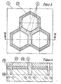
- Figur 2 die Stirnseite eines Rohrbündels und gestrichelt den Querschnitt im mittleren Bereich,
- Figur 3 eine Draufsicht auf die mit beheizbaren Nuten ausgerüstete, an das Rohrbündel gemäß Figur 2 andrückbare Platte,
- Figur 4 einen Querschnitt längs der Linie IV-IV durch die in Figur 3 dargestellte Platte.
- In Figur 1 stellt 1 die an das Hohlprofilbündel andrückbare Platte mit der Nut 2 dar. Der Boden 3 der Nut ist durch Heizelemente 4 oder mit einem Heizmediun durchströmbare Kanäle 4 auf die Schmelztemperatur des Kunststoffes oder darüber heizbar. Der Eingang 5 der Nut ist über einen Kühlmittelkanal 6 kühlbar. Die Versorgungsleitungen für die Heiz-oder Kühlelente 4 bzw. 6 sind aus Gründen der übersichtlichkeit nicht eingezeichnet. Der über die Schmelztemperatur heizbare Teil 8 der Platte 2 besteht vorzugsweise aus Metall, wie Stahl, Aluninium oder Messing. Der thermisch isolierte Teil 9 kann ebenfalls aus Metall bestehen. Dazwischen ist zweckmäßigerweise eine Schicht 10 aus wärmeisolierendem Material, z.B. ein Mineralfaservlies oder eine wärmebeständige, gegebenenfalls mit Fasern oder Geweben verstärkte Kunststoffpreßmasse oder ein Keramikkörper, eingelegt. Manchmal genügt es, wenn der thermisch isolierte Teil 9 selbst aus einem derartigen wärmeisolierenden Material besteht.
- Zun Verschweißen zweier Endstücke 11, 12 aus Polyphenylenoxid wird der Boden 3 der Nut auf 240 bis 280°C geheizt und der Eingang 5 durch Kühlung auf einer Temperatur unterhalb 130°C gehalten. Es wird allgemein bevorzugt, den Eingangsbereich auf einer Temperatur unterhalb der Erweichungstemperatur des Kunststoffes zu halten. Der über die Einpreßkraft erzeugte Druck im beheizten Nutbereich liegt z.B. zwischen 0,6 und 100 N/cm2. Dadurch fließen Schmelzströme 13 van Boden 3 der Nut in den Eingangsspalt, wo sie bei Berührung mit der kühlen Wandung 5 des Eingangs erstarren. Sobald das in den beheizten Nutraun hineinragende Material homogen zusammengeschmolzen und der Nutraum völlig ausgefüllt ist, kann die Heizung abgestellt und das Material in der Nut unter die Schmelztemperatur, vorzugsweise unter die Erweichungstemperatur abgekühlt werden. Wenn dies durch Wärmeabgabe an die Umgebungsluft nicht schnell genug geschieht, kann die Abkühlung durch ein Kühlsystem unterstützt werden. Dazu können die Kanäle 4 oder besondere Kühlmittelkanäle 14 mit einem Kühlmittel durchströmt werden. Nach der Abkühlung kann die Schweißstelle aus der Nut herausgenommen werden. Dies wird durch einen schwach keilförmigen Querschnitt der Nut erleichtert.
- Das in Figur 2 dargestellte Rohrbündel ist aus drei kreisrunden Rohren 20 mit sechseekförmig aufgeweiteten Endstücken 21 zusammengesetzt. Die Endstücke liegen in den Bereichen 22 flächig aneinander. Die Wanddicke 23 beträgt in diesem Bereich beispielsweise 1 bis 8 mm, in den Bereichen 24 die Hälfte, also 0,5 bis 4 mm.
- Zum Verschweißen wird das in Figur 2 gezeigte Rohrbündel in die Platte 1 gemäß Figur 3 eingesenkt. Die zum Verschweißen der Endstücke vorgesehenen Nuten 2 haben im Eingangsbereich 26 eine größere Weite als die Wanddicke 23, können aber zum Nutgrund hin auf eine der Wanddicke 23 entsprechender Weite oder noch weniger zusammenlaufen. Die Randnut 27 dient nur dazu, die Außenwand auf die gleiche Ebene 28 wie die zu verschweißenden Bereiche abzuschmelzen.
- Grundsätzlich genügt eine Platte 1 zur Durchführung des Verfahrens. Es ist jedoch bevorzugt, die beiden Stirnseiten eines Bündels gleichzeitig mittels zweier Platten 1 zu verschweißen. Diese werden während des Schweißverfahrens parallel zueinander um den Betrag, un den die Endstücke in die Nuten eingesenkt werden, aufeinander zubewegt. Dazu wird zweckmäßig eine Schubvorrichtung benutzt, die wenigstens eine der Platten bewegt und den zum Verschweißen erforderlichen Druck erzeugt. Die Platten sind parallel verschiebbar auf einem Traggestell angeordnet, welches vorzugsweise noch eine Haltevorrichtung zur Aufnahme des Bündels vor und nach dem Schweißvorgang trägt.
Claims (10)
dadurch gekennzeichnet,
daß der Boden der Nuten auf oder über die Schmelztemperatur des Kunststoffes heizbar und der Eingang der Nuten allseitig von dem Bodenbereich thermisch isoliert ist.
Applications Claiming Priority (2)
| Application Number | Priority Date | Filing Date | Title |
|---|---|---|---|
| DE19853522190 DE3522190A1 (de) | 1985-06-21 | 1985-06-21 | Verfahren und vorrichtung zum stirnseitigen verschweissen von buendeln von formkoerpern aus thermoplastischem kunststoff unter druckanwendung |
| DE3522190 | 1985-06-21 |
Publications (2)
| Publication Number | Publication Date |
|---|---|
| EP0208913A1 true EP0208913A1 (de) | 1987-01-21 |
| EP0208913B1 EP0208913B1 (de) | 1989-01-18 |
Family
ID=6273803
Family Applications (1)
| Application Number | Title | Priority Date | Filing Date |
|---|---|---|---|
| EP86107987A Expired EP0208913B1 (de) | 1985-06-21 | 1986-06-11 | Verfahren und Vorrichtung zum stirnseitigen Verschweissen von Bündeln von Formkörpern aus thermoplastischem Kunststoff unter Druckanwendung |
Country Status (7)
| Country | Link |
|---|---|
| US (1) | US4797173A (de) |
| EP (1) | EP0208913B1 (de) |
| JP (1) | JPH0733070B2 (de) |
| AU (1) | AU581999B2 (de) |
| CA (1) | CA1267516A (de) |
| DE (2) | DE3522190A1 (de) |
| ZA (1) | ZA864619B (de) |
Cited By (3)
| Publication number | Priority date | Publication date | Assignee | Title |
|---|---|---|---|---|
| DE4013471A1 (de) * | 1990-04-27 | 1991-10-31 | Fischer Ag Georg | Einrichtung zum stirnseitigen verschweissen von kunststoffteilen |
| WO1997006397A1 (de) * | 1995-08-09 | 1997-02-20 | Steag Aktiengesellschaft | Speicherblock für regenerativ-wärmetauscher |
| FR3006232A1 (fr) * | 2013-05-28 | 2014-12-05 | Bieder Alexandra Singer | Procede d'assemblage de tubes en plastique a partir d'une source de chaleur permettant par une soudure autogene, d'obtenir un materiau homogene aux qualites esthetiques, mecaniques et de lumieres |
Families Citing this family (10)
| Publication number | Priority date | Publication date | Assignee | Title |
|---|---|---|---|---|
| MX9204071A (es) * | 1991-07-12 | 1993-04-01 | Hexcel Corp | Metodo y aparato para hacer estructuras alveolares termoplasticas, termicamente fundidas. |
| US6001291A (en) * | 1996-02-07 | 1999-12-14 | Cesaroni; Anthony Joseph | Method of bonding tubes into an article |
| JP2798645B2 (ja) * | 1996-04-25 | 1998-09-17 | 株式会社アイメス | プリンタ |
| US6497775B2 (en) * | 2001-04-11 | 2002-12-24 | Delphi Technologies, Inc. | Method and apparatus for manufacturing a vehicle cross car beam or other structural, functional articles out of multiple materials with optimum material utilization |
| JP2005001268A (ja) * | 2003-06-12 | 2005-01-06 | Munekata Co Ltd | 熱可塑性樹脂成形品に用いる熱溶着装置 |
| DE10352112A1 (de) * | 2003-11-04 | 2005-06-16 | Veka Ag | Verfahren zur Herstellung einer thermoplastischen Kunststoffplatte mit wenigstens einer geglätteten Seitenkante und Vorrichtung dafür |
| DE102004027561A1 (de) * | 2003-11-04 | 2005-12-29 | Veka Ag | Glättungsvorrichtung und Kantenbearbeitungssystem für eine Seitenkante einer thermoplastischen Kunststoffplatte |
| US10364375B2 (en) * | 2010-06-14 | 2019-07-30 | Gates Corporation | Article with self-bonding fully cured elastomer |
| KR101666523B1 (ko) * | 2014-11-27 | 2016-10-17 | 깨끗한나라 주식회사 | 수분해성 섬유 시트 및 이의 제조 방법 |
| CN113681159B (zh) * | 2021-08-20 | 2022-08-12 | 山东大学 | 一种金属和热塑性复合材料激光压焊装置及其方法和应用 |
Citations (5)
| Publication number | Priority date | Publication date | Assignee | Title |
|---|---|---|---|---|
| DE840668C (de) * | 1950-09-20 | 1952-06-05 | Sattler Atlan Werk Kg L | Verfahren zum Verschweissen der Randkanten von folien- oder plattenfoermigen thermoplastischen Kunststoffen |
| US2994361A (en) * | 1958-06-18 | 1961-08-01 | Taf Res Corp | Method and apparatus for sealing thermoplastic material |
| DE2420477A1 (de) * | 1973-05-02 | 1974-11-21 | Sig Schweiz Industrieges | Verfahren zur bildung einer schweissnaht und vorrichtung zur durchfuehrung des verfahrens |
| US4085185A (en) * | 1975-04-03 | 1978-04-18 | Adair Edwin Lloyd | Method of sealing concentric tube ends to make sealed dual-wall tube |
| DE2603615C3 (de) * | 1976-01-30 | 1979-06-13 | Masashi Daito Osaka Kato (Japan) | Vorrichtung zum Herstellen eines Rohrbfindels aus thermoplastischem Kunststoff |
Family Cites Families (4)
| Publication number | Priority date | Publication date | Assignee | Title |
|---|---|---|---|---|
| LU57593A1 (de) * | 1967-12-20 | 1969-04-08 | ||
| US3880695A (en) * | 1972-10-30 | 1975-04-29 | Abbott Lab | Apparatus for bonding sealing ring to a closure |
| DE2708898C3 (de) * | 1977-03-02 | 1981-05-21 | Wavin B.V., Zwolle | Verfahren und Vorrichtung zum Verbinden von Kunststoffrohren durch Schweißen |
| US4174991A (en) * | 1978-11-13 | 1979-11-20 | The Akro Corporation | Process of laminating carpet to elastomeric backing |
-
1985
- 1985-06-21 DE DE19853522190 patent/DE3522190A1/de not_active Withdrawn
-
1986
- 1986-06-11 EP EP86107987A patent/EP0208913B1/de not_active Expired
- 1986-06-11 DE DE8686107987T patent/DE3661805D1/de not_active Expired
- 1986-06-16 US US06/874,649 patent/US4797173A/en not_active Expired - Fee Related
- 1986-06-18 CA CA000511826A patent/CA1267516A/en not_active Expired - Lifetime
- 1986-06-19 JP JP61141549A patent/JPH0733070B2/ja not_active Expired - Fee Related
- 1986-06-20 AU AU58933/86A patent/AU581999B2/en not_active Ceased
- 1986-06-20 ZA ZA864619A patent/ZA864619B/xx unknown
Patent Citations (5)
| Publication number | Priority date | Publication date | Assignee | Title |
|---|---|---|---|---|
| DE840668C (de) * | 1950-09-20 | 1952-06-05 | Sattler Atlan Werk Kg L | Verfahren zum Verschweissen der Randkanten von folien- oder plattenfoermigen thermoplastischen Kunststoffen |
| US2994361A (en) * | 1958-06-18 | 1961-08-01 | Taf Res Corp | Method and apparatus for sealing thermoplastic material |
| DE2420477A1 (de) * | 1973-05-02 | 1974-11-21 | Sig Schweiz Industrieges | Verfahren zur bildung einer schweissnaht und vorrichtung zur durchfuehrung des verfahrens |
| US4085185A (en) * | 1975-04-03 | 1978-04-18 | Adair Edwin Lloyd | Method of sealing concentric tube ends to make sealed dual-wall tube |
| DE2603615C3 (de) * | 1976-01-30 | 1979-06-13 | Masashi Daito Osaka Kato (Japan) | Vorrichtung zum Herstellen eines Rohrbfindels aus thermoplastischem Kunststoff |
Cited By (3)
| Publication number | Priority date | Publication date | Assignee | Title |
|---|---|---|---|---|
| DE4013471A1 (de) * | 1990-04-27 | 1991-10-31 | Fischer Ag Georg | Einrichtung zum stirnseitigen verschweissen von kunststoffteilen |
| WO1997006397A1 (de) * | 1995-08-09 | 1997-02-20 | Steag Aktiengesellschaft | Speicherblock für regenerativ-wärmetauscher |
| FR3006232A1 (fr) * | 2013-05-28 | 2014-12-05 | Bieder Alexandra Singer | Procede d'assemblage de tubes en plastique a partir d'une source de chaleur permettant par une soudure autogene, d'obtenir un materiau homogene aux qualites esthetiques, mecaniques et de lumieres |
Also Published As
| Publication number | Publication date |
|---|---|
| US4797173A (en) | 1989-01-10 |
| AU581999B2 (en) | 1989-03-09 |
| DE3522190A1 (de) | 1987-01-02 |
| ZA864619B (en) | 1987-02-25 |
| AU5893386A (en) | 1986-12-24 |
| CA1267516A (en) | 1990-04-10 |
| EP0208913B1 (de) | 1989-01-18 |
| DE3661805D1 (en) | 1989-02-23 |
| JPS61295026A (ja) | 1986-12-25 |
| JPH0733070B2 (ja) | 1995-04-12 |
Similar Documents
| Publication | Publication Date | Title |
|---|---|---|
| EP0167938B1 (de) | Wärmetauscherkörper aus Kunststoff | |
| EP0208913B1 (de) | Verfahren und Vorrichtung zum stirnseitigen Verschweissen von Bündeln von Formkörpern aus thermoplastischem Kunststoff unter Druckanwendung | |
| EP0083030B1 (de) | Verfahren zur Herstellung einer gasdicht verschlossenen Hohlkammerplatte aus Kunststoff | |
| DE1908207A1 (de) | Beheizbarer Spinnbalken zum Erzeugen von Endlosfaeden aus synthetischem Polymeren | |
| DE2345049A1 (de) | Verfahren und vorrichtung zur herstellung von thermoplastischen mehrschichtwerkstoffen | |
| EP0050363B1 (de) | Verfahren und Vorrichtung zum Herstellen von Wärmeaustauscherelementen | |
| DE4019632C2 (de) | Vorrichtung zum Erhitzen von plattenförmigen Teilen aus tiefziehfähigem Kunststoff | |
| EP0243574B1 (de) | Wärmetauscher und Verfahren zum Herstellen von Wärmetauschern | |
| EP0226094B1 (de) | Verfahren zum Verbinden von Hohlprofilkörpern mit Formkörpern aus thermoplastischem Kunststoff | |
| DE2634139A1 (de) | Verbindungsverfahren | |
| EP0028284B1 (de) | Wärmetauscher aus Kunststoff | |
| AT393902B (de) | Plattenstapel | |
| DE2405943B2 (de) | Heissluftsiegelvorrichtung zum verbinden von zwei verpackungsmaterialbahnen | |
| DE69307126T2 (de) | Verfahren zur herstellung von wärmetauschern | |
| DE3027045A1 (de) | Flach-hohlkoerper, insbesondere lueftungs- und drainage- bzw. absorber-platte | |
| EP0484721B1 (de) | Verfahren und Vorrichtung zur Extrusion von Hohlkammerplatten aus thermoplastischem Kunststoff | |
| AT412767B (de) | Verfahren zum herstellen von länglichen gegenständen sowie mit diesem verfahren hergestellter gegenstand | |
| DE4340381A1 (de) | Verfahren und Vorrichtung zum Verformen und Verschließen der Ränder von Hohlkammerplatten aus einem thermoplastischen Material | |
| DE2927717C2 (de) | ||
| DE19845652C2 (de) | Vorrichtung zum Glätten und Kühlen bzw. Kühlen einer extrudierten Materialbahn | |
| DE10021728A1 (de) | Verfahren zum Herstellen von länglichen Gegenständen | |
| DE3008055C2 (de) | ||
| DE2740291A1 (de) | Verfahren und vorrichtung zum verbinden von kunststoffkoerpern mit bindemittelhaltigen formteilen aus beispielsweise beton oder zement | |
| DE1220998B (de) | Verfahren und Vorrichtung zum vorbereitenden Erwaermen einer fortlaufend zugefuehrten, insbesondere durch Tiefziehen zu verformenden Folienbahn aus thermoplastischem Kunststoff | |
| DE8419977U1 (de) | Wärmetauscherkörper aus Kunststoff |
Legal Events
| Date | Code | Title | Description |
|---|---|---|---|
| PUAI | Public reference made under article 153(3) epc to a published international application that has entered the european phase |
Free format text: ORIGINAL CODE: 0009012 |
|
| AK | Designated contracting states |
Kind code of ref document: A1 Designated state(s): BE DE FR GB IT NL |
|
| 17P | Request for examination filed |
Effective date: 19870627 |
|
| 17Q | First examination report despatched |
Effective date: 19880503 |
|
| GRAA | (expected) grant |
Free format text: ORIGINAL CODE: 0009210 |
|
| AK | Designated contracting states |
Kind code of ref document: B1 Designated state(s): BE DE FR GB IT NL |
|
| ITF | It: translation for a ep patent filed | ||
| REF | Corresponds to: |
Ref document number: 3661805 Country of ref document: DE Date of ref document: 19890223 |
|
| ET | Fr: translation filed | ||
| GBT | Gb: translation of ep patent filed (gb section 77(6)(a)/1977) | ||
| PLBE | No opposition filed within time limit |
Free format text: ORIGINAL CODE: 0009261 |
|
| STAA | Information on the status of an ep patent application or granted ep patent |
Free format text: STATUS: NO OPPOSITION FILED WITHIN TIME LIMIT |
|
| 26N | No opposition filed | ||
| ITTA | It: last paid annual fee | ||
| PGFP | Annual fee paid to national office [announced via postgrant information from national office to epo] |
Ref country code: BE Payment date: 19960731 Year of fee payment: 11 |
|
| PG25 | Lapsed in a contracting state [announced via postgrant information from national office to epo] |
Ref country code: BE Effective date: 19970630 |
|
| PGFP | Annual fee paid to national office [announced via postgrant information from national office to epo] |
Ref country code: NL Payment date: 19970630 Year of fee payment: 12 |
|
| BERE | Be: lapsed |
Owner name: ROHM G.M.B.H. Effective date: 19970630 |
|
| PG25 | Lapsed in a contracting state [announced via postgrant information from national office to epo] |
Ref country code: NL Free format text: LAPSE BECAUSE OF NON-PAYMENT OF DUE FEES Effective date: 19990101 |
|
| NLV4 | Nl: lapsed or anulled due to non-payment of the annual fee |
Effective date: 19990101 |
|
| PGFP | Annual fee paid to national office [announced via postgrant information from national office to epo] |
Ref country code: GB Payment date: 19990525 Year of fee payment: 14 |
|
| PG25 | Lapsed in a contracting state [announced via postgrant information from national office to epo] |
Ref country code: GB Free format text: LAPSE BECAUSE OF NON-PAYMENT OF DUE FEES Effective date: 20000611 |
|
| GBPC | Gb: european patent ceased through non-payment of renewal fee |
Effective date: 20000611 |
|
| PGFP | Annual fee paid to national office [announced via postgrant information from national office to epo] |
Ref country code: FR Payment date: 20010618 Year of fee payment: 16 |
|
| PGFP | Annual fee paid to national office [announced via postgrant information from national office to epo] |
Ref country code: DE Payment date: 20010822 Year of fee payment: 16 |
|
| PG25 | Lapsed in a contracting state [announced via postgrant information from national office to epo] |
Ref country code: DE Free format text: LAPSE BECAUSE OF NON-PAYMENT OF DUE FEES Effective date: 20030101 |
|
| PG25 | Lapsed in a contracting state [announced via postgrant information from national office to epo] |
Ref country code: FR Free format text: LAPSE BECAUSE OF NON-PAYMENT OF DUE FEES Effective date: 20030228 |
|
| REG | Reference to a national code |
Ref country code: FR Ref legal event code: ST |
|
| PG25 | Lapsed in a contracting state [announced via postgrant information from national office to epo] |
Ref country code: IT Free format text: LAPSE BECAUSE OF NON-PAYMENT OF DUE FEES;WARNING: LAPSES OF ITALIAN PATENTS WITH EFFECTIVE DATE BEFORE 2007 MAY HAVE OCCURRED AT ANY TIME BEFORE 2007. THE CORRECT EFFECTIVE DATE MAY BE DIFFERENT FROM THE ONE RECORDED. Effective date: 20050611 |