EP0207239B1 - Werkstückeinspannvorrichtung an einer Kreissägemaschine - Google Patents
Werkstückeinspannvorrichtung an einer Kreissägemaschine Download PDFInfo
- Publication number
- EP0207239B1 EP0207239B1 EP86105262A EP86105262A EP0207239B1 EP 0207239 B1 EP0207239 B1 EP 0207239B1 EP 86105262 A EP86105262 A EP 86105262A EP 86105262 A EP86105262 A EP 86105262A EP 0207239 B1 EP0207239 B1 EP 0207239B1
- Authority
- EP
- European Patent Office
- Prior art keywords
- clamping jaw
- clamping
- workpiece
- sawing machine
- rotatable
- Prior art date
- Legal status (The legal status is an assumption and is not a legal conclusion. Google has not performed a legal analysis and makes no representation as to the accuracy of the status listed.)
- Expired
Links
Images


Classifications
-
- B—PERFORMING OPERATIONS; TRANSPORTING
- B23—MACHINE TOOLS; METAL-WORKING NOT OTHERWISE PROVIDED FOR
- B23D—PLANING; SLOTTING; SHEARING; BROACHING; SAWING; FILING; SCRAPING; LIKE OPERATIONS FOR WORKING METAL BY REMOVING MATERIAL, NOT OTHERWISE PROVIDED FOR
- B23D47/00—Sawing machines or sawing devices working with circular saw blades, characterised only by constructional features of particular parts
- B23D47/04—Sawing machines or sawing devices working with circular saw blades, characterised only by constructional features of particular parts of devices for feeding, positioning, clamping, or rotating work
-
- B—PERFORMING OPERATIONS; TRANSPORTING
- B23—MACHINE TOOLS; METAL-WORKING NOT OTHERWISE PROVIDED FOR
- B23D—PLANING; SLOTTING; SHEARING; BROACHING; SAWING; FILING; SCRAPING; LIKE OPERATIONS FOR WORKING METAL BY REMOVING MATERIAL, NOT OTHERWISE PROVIDED FOR
- B23D45/00—Sawing machines or sawing devices with circular saw blades or with friction saw discs
- B23D45/06—Sawing machines or sawing devices with circular saw blades or with friction saw discs with a circular saw blade arranged underneath a stationary work-table
- B23D45/068—Sawing machines or sawing devices with circular saw blades or with friction saw discs with a circular saw blade arranged underneath a stationary work-table the saw blade being adjustable according to depth or angle of cut
-
- Y—GENERAL TAGGING OF NEW TECHNOLOGICAL DEVELOPMENTS; GENERAL TAGGING OF CROSS-SECTIONAL TECHNOLOGIES SPANNING OVER SEVERAL SECTIONS OF THE IPC; TECHNICAL SUBJECTS COVERED BY FORMER USPC CROSS-REFERENCE ART COLLECTIONS [XRACs] AND DIGESTS
- Y10—TECHNICAL SUBJECTS COVERED BY FORMER USPC
- Y10T—TECHNICAL SUBJECTS COVERED BY FORMER US CLASSIFICATION
- Y10T83/00—Cutting
- Y10T83/748—With work immobilizer
- Y10T83/7487—Means to clamp work
-
- Y—GENERAL TAGGING OF NEW TECHNOLOGICAL DEVELOPMENTS; GENERAL TAGGING OF CROSS-SECTIONAL TECHNOLOGIES SPANNING OVER SEVERAL SECTIONS OF THE IPC; TECHNICAL SUBJECTS COVERED BY FORMER USPC CROSS-REFERENCE ART COLLECTIONS [XRACs] AND DIGESTS
- Y10—TECHNICAL SUBJECTS COVERED BY FORMER USPC
- Y10T—TECHNICAL SUBJECTS COVERED BY FORMER US CLASSIFICATION
- Y10T83/00—Cutting
- Y10T83/748—With work immobilizer
- Y10T83/7587—Gapped work-constrainer
-
- Y—GENERAL TAGGING OF NEW TECHNOLOGICAL DEVELOPMENTS; GENERAL TAGGING OF CROSS-SECTIONAL TECHNOLOGIES SPANNING OVER SEVERAL SECTIONS OF THE IPC; TECHNICAL SUBJECTS COVERED BY FORMER USPC CROSS-REFERENCE ART COLLECTIONS [XRACs] AND DIGESTS
- Y10—TECHNICAL SUBJECTS COVERED BY FORMER USPC
- Y10T—TECHNICAL SUBJECTS COVERED BY FORMER US CLASSIFICATION
- Y10T83/00—Cutting
- Y10T83/768—Rotatable disc tool pair or tool and carrier
- Y10T83/7684—With means to support work relative to tool[s]
- Y10T83/773—Work-support includes passageway for tool [e.g., slotted table]
-
- Y—GENERAL TAGGING OF NEW TECHNOLOGICAL DEVELOPMENTS; GENERAL TAGGING OF CROSS-SECTIONAL TECHNOLOGIES SPANNING OVER SEVERAL SECTIONS OF THE IPC; TECHNICAL SUBJECTS COVERED BY FORMER USPC CROSS-REFERENCE ART COLLECTIONS [XRACs] AND DIGESTS
- Y10—TECHNICAL SUBJECTS COVERED BY FORMER USPC
- Y10T—TECHNICAL SUBJECTS COVERED BY FORMER US CLASSIFICATION
- Y10T83/00—Cutting
- Y10T83/768—Rotatable disc tool pair or tool and carrier
- Y10T83/7755—Carrier for rotatable tool movable during cutting
- Y10T83/7763—Tool carrier reciprocable rectilinearly
- Y10T83/7776—With means to reciprocate carrier
- Y10T83/778—And means to rotate tool
-
- Y—GENERAL TAGGING OF NEW TECHNOLOGICAL DEVELOPMENTS; GENERAL TAGGING OF CROSS-SECTIONAL TECHNOLOGIES SPANNING OVER SEVERAL SECTIONS OF THE IPC; TECHNICAL SUBJECTS COVERED BY FORMER USPC CROSS-REFERENCE ART COLLECTIONS [XRACs] AND DIGESTS
- Y10—TECHNICAL SUBJECTS COVERED BY FORMER USPC
- Y10T—TECHNICAL SUBJECTS COVERED BY FORMER US CLASSIFICATION
- Y10T83/00—Cutting
- Y10T83/869—Means to drive or to guide tool
- Y10T83/8773—Bevel or miter cut
Definitions
- the invention relates to a sawing machine with a machine frame, with a slotted rotary plate which can be rotated about a vertical axis and which accommodates a workpiece to be sawn, with a motor-driven circular saw blade with a horizontal axis of rotation which can be passed through the slot of the rotating plate when sawing from bottom to top a clamping bridge fixed to the frame, projecting above the rotating plate and with a clamping device carried by the clamping bridge for clamping the workpiece on the rotating plate.
- a solid block of metal or wood is used to clamp the workpiece, which is inserted between the workpiece and the clamping device, which can only be adjusted vertically.
- the workpiece is then clamped against the rotating plate by the block by vertically adjusting the clamping device. Since the upper stroke of the saw blade is generally not limited, the saw blade cuts into the block after it has cut through the workpiece, which must therefore be replaced by a new block after several saw cuts. Otherwise the desired high clamping accuracy is usually not achievable.
- the clamping device comprises a vertically up and down jaw that can be placed on the workpiece, that the jaw is rotatable about the axis of rotation of the rotary plate, and that the jaw is displaceable perpendicular to its axis of rotation in a sliding guide.
- the sawing machine shown diagrammatically in FIG. 1 comprises a block-shaped machine frame 1, in which a rotating plate 2 serving as a work table is rotatably mounted about a vertical axis in a manner known per se.
- the rotating plate 2 has a diametrical slot 3, through which a circular saw blade 4 can be passed from bottom to top.
- the saw blade 4 rotating about a horizontal axis of rotation is driven by an electric motor, not shown.
- a lifting and lowering device for the circular saw blade 4, which is also known per se and is therefore not shown in its own right, is connected to the rotary plate 2 to form a unit which can be rotated about the vertical axis mentioned.
- a workpiece W to be sawn (FIG. 2) is placed on the rotating plate 2 in a known manner and brought into contact with a stop 5 located above the rotating plate. In this position, the workpiece is clamped on the rotary plate 2 by a vertically adjustable clamping device 6.
- the tensioning device 6 is mounted on a tensioning bridge 7 projecting vertically above the rotating plate 2.
- the workpiece held in this way can now be cut by moving the saw blade 4 from bottom to top, the cuts being able to be made perpendicularly or at an angle different from 90 ° to the workpiece axis.
- the clamping device 6 comprises, as an essential component, a vertically up and down movable clamping jaw 11 which can be placed on the workpiece W and is fork-shaped and has a vertical slot for the entry of the circular saw blade 4.
- the length or height of this slot is at least equal to the maximum lifting height of the circular saw blade, so that even if no or only a very thin workpiece is sawn, the clamping jaw 11 rests with its free ends practically directly on the rotary plate 2, the clamping device 6 cannot be damaged by the saw blade 4.
- a T-shaped guide pin 14 protrudes downward from a guide plate 13 arranged above the clamping jaw 11, which is also part of the clamping device 6, which engages in a complementary, T-shaped groove 15 (FIG. 5) of the clamping jaw 11.
- the pin 14 and the groove 15 form a sliding guide, by means of which the clamping jaw 11 on the underside of the guide plate 11 can be pushed back and forth on a straight path, this path being shown in FIGS. 2 and 5 in the plane of the drawing and in FIG 3 is perpendicular to the plane of the drawing.
- a circular-cylindrical pivot pin 16 is connected in one piece (see FIG. 5) to the guide pin 14 and has been given the profile of a double-T profile by an annular groove 17.
- An eccentric shaft 18 mounted in the guide plate 13 engages in the annular groove 17 and can be rotated by a handle 19.
- the clamping jaw 11 can be clamped on the underside of the guide plate 13.
- the pivot 16 is so horizontal
- the clamping jaw 11 can be placed largely centrally on this in any position of the workpiece abutting the stop 5, so that a precise clamping is possible, while at the same time the slot 12 of the clamping jaw 11 can always be aligned such that the saw blade 4 penetrate into it without contact can.
- the direction of displacement of the clamping jaw 11 on the guide plate 13 by means of the slide guide mentioned runs perpendicular to the axis of rotation of the clamping jaw 11 and the rotary plate 2.
- the guide plate 13 and thus the clamping jaw 11 are mounted vertically up and down in the clamping bridge 7 by means of guide rods 22, 23 projecting rigidly from the plate 13.
- the guide rod 22 carries a scale 24 on which the respective adjustment height can be read.
- the guide plate 13 is rotatably supported by means of a recess 25 machined into it, a ring 26 which fits into the recess 25 and bears against the base thereof, and a continuous split pin 27 at the lower end 28 of a screw spindle 29. If the screw spindle 29 is turned up or down, the guide plate 13 guided in a non-rotatable manner by the guide rods 22, 23 moves up or down.
- the screw spindle 29 engages with its external thread in an internally threaded section 31 of a hollow piston rod 32 which is firmly connected to a piston 33.
- the piston 33 and thus the piston rod 32 are displaceable in a pressure medium cylinder 34 in a manner known per se, the screw spindle and thus the guide plate 13 being carried along.
- the piston 33 can in the cylinder 34 with a corresponding pressure medium supply (compressed air or hydraulic oil) only a very limited stroke of z. B. 8 mm. This maximum stroke is indicated by the dash-dot line in FIG. 4 by the arrow X.
- the screw spindle 29 has an axially parallel longitudinal groove 35 on its outside (located on the left in FIG. 4). In the area below the threaded section 31 provided in the piston rod 32, the screw spindle is loosely surrounded by a cylindrical bush 36. A spring 39 projects into the longitudinal groove 35 from the inner wall of this socket and is held inward by screws 37, 38. In this way, there is a rotational connection between the bush 36 and the screw spindle 29, but the screw spindle 29 can move axially relative to the bush 36.
- a bevel gear 42 which meshes with a further bevel gear 43, is connected in a rotationally fixed manner to the bushing 36 by the screw 37 and further screws 41.
- the bevel gear 43 can be rotated by means of a handwheel 44 rotatably mounted in the tension bridge 7, the bush 36 being carried along by the bevel gear 42. This causes the spindle 29 to rotate via the spring 39, which at the same time moves relatively to the piston rod 32 because of the longitudinal groove 35. Since the pressure medium cylinder 34 containing the piston rod 32 is fixed in position on the tension bridge 7, the guide plate 13 rotatably connected to the screw spindle 29 can thus be moved downwards and upwards over a longer distance. This displacement of the guide plate 13 serves to roughly adjust the clamping jaw 11 relative to a tool to be sawn. This rough adjustment is preferably carried out to such an extent that the clamping jaw 11 sits loosely on the workpiece with its free, fork-shaped ends.
- the pressure medium cylinder 34 is actuated so that its piston rod 32 is pressed down by the aforementioned small distance X with great force. Since the clamping jaw 11 is also firmly connected to the piston rod 32 via the screw spindle 29 and the guide plate 13, the clamping jaw is thus pressed onto the workpiece W with great pressure and holds it in the desired position on the rotary plate 2.
Landscapes
- Engineering & Computer Science (AREA)
- Mechanical Engineering (AREA)
- Sawing (AREA)
- Polishing Bodies And Polishing Tools (AREA)
- Stringed Musical Instruments (AREA)
- Harvester Elements (AREA)
- Mechanical Treatment Of Semiconductor (AREA)
- Dry Shavers And Clippers (AREA)
Description
- Die Erfindung betrifft eine Sägemaschine mit einem Maschinengestell, mit einer geschlitzten, um eine vertikale Achse drehbaren, der Aufnahme eines zu sägenden Werkstückes dienenden Drehplatte, mit einem beim Sägen von unten nach oben durch den Schlitz der Drehplatte hindurchführbaren, motorgetriebenen Kreissägeblatt mit horizontaler Drehachse, mit einer gestellfesten, die Drehplatte überragenden Spannbrücke und mit einer von der Spannbrücke getragenen Spanneinrichtung zum Festspannen des Werkstückes auf der Drehplatte.
- Bei bekannten Sägemaschinen dieser Art wird zum Festspannen des Werkstückes ein massiver Klotz aus Metall oder Holz verwendet, der zwischen das Werkstück und die lediglich vertikal verstellbare Spanneinrichtung eingesetzt wird. Durch vertikales Verstellen der Spanneinrichtung wird dann das Werkstück von dem Klotz gegen die Drehplatte gespannt. Da der Hub des Sägeblattes nach oben in der Regel nicht begrenzt ist, schneidet das Sägeblatt, nachdem es das Werkstück durchschnitten hat, in den Klotz ein, der daher nach mehreren Sägeschnitten durch einen neuen Klotz ersetzt werden muß. Andernfalls ist die gewünschte, hohe Spanngenauigkeit meist nicht erzielbar.
- Es ist Aufgabe der Erfindung, eine gattungsgemäße Sägemaschine so auszubilden, daß die Spanneinrichtung mit wenigen Handgriffen rasch und genau auf verschiedene Werkstückgrößen und Schnittwinkel einstellbar ist, ohne daß dabei die Gefahr einer Beschädigung der Spanneinrichtung während des Sägens entsteht.
- Die Aufgabe wird erfindungsgemäß dadurch gelöst, daß die Spanneinrichtung eine auf das Werkstück aufsetzbare, vertikal auf- und abbewegliche Spannbacke umfaßt, daß die Spannbacke um die Drehachse der Drehplatte verdrehbar ist, und daß die Spannbacke senkrecht zu ihrer Drehachse in einer Gleitführung verschiebbar ist.
- Die nachstehende Beschreibung einer bevorzugten Ausführungsform der Erfindung dient im Zusammenhang mit beiliegender Zeichnung der weiteren Erläuterung. Es zeigen:
- Fig. 1 eine schaubildliche Ansicht einer Kreissägemaschine mit einem von unten her in ein Werkstück einführbaren Sägeblatt;
- Fig. 2 eine teilweise geschnittene Seitenansicht der Kreissägemaschine;
- Fig. 3 eine Ansicht der Maschine in Richtung des Pfeiles A in Fig. 2;
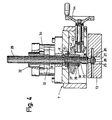
- Fig. 4 eine vergrößerte Schnittansicht entlang der Linie 4 - 4 in Fig. 2 und
- Fig. 5 eine vergrößerte Teilschnittansicht entlang der Linie 5 - 5 in Fig. 3.
- Die in Fig. 1 schaubildlich dargestellte Sägemaschine umfaßt ein blockförmiges Maschinengestell 1, in dem in an sich bekannter Weise eine als Arbeitstisch dienende Drehplatte 2 um eine vertikale Achse drehbar gelagert ist. Die Drehplatte 2 weist einen diametralen Schlitz 3 auf, durch den hindurch ein Kreissägeblatt 4 von unten nach oben hindurchführbar ist. Das um eine horizontal verlaufende Drehachse rotierende Sägeblatt 4 wird von einem nicht dargestellten Elektromotor angetrieben. Eine ebenfalls an sich bekannte und daher nicht eigenst dargestellte Hebe- und Senkeinrichtung für das Kreissägeblatt 4 ist mit der Drehplatte 2 zu einer um die erwähnte vertikale Achse drehbaren Einheit verbunden.
- Ein zu zersägendes Werkstück W (Fig. 2) wird in bekannter Weise auf die Drehplatte 2 gelegt und in Anlage mit einem über der Drehplatte befindlichen Anschlag 5 gebracht. In dieser Lage wird das Werkstück von einer vertikal verstellbaren Spanneinrichtung 6 auf der Drehplatte 2 festgeklemmt. Die Spanneinrichtung 6 ist an einer die Drehplatte 2 überragenden Spannbrücke 7 vertikal verstellbar gelagert.
- Das auf diese Weise festgehaltene Werkstück kann nun durch Verschieben des Sägeblattes 4 von unten nach oben geschnitten werden, wobei die Schnitte senkrecht oder in einem von 90° verschiedenen Winkel zur Werkstückachse geführt werden können.
- Wie insbesondere aus Fig. 2 und 3 hervorgeht, umfaßt die Spanneinrichtung 6 als wesentlichen Bestandteil eine auf das Werkstück W aufsetzbare, vertikal aufund abbewegliche Spannbacke 11, die gabelförmig ausgebildet ist und einen vertikalen Schlitz für den Eintritt des Kreissägeblatts 4 aufweist. Die Länge oder Höhe dieses Schlitzes ist mindestens gleich der maximalen Hubhöhe des Kreissägeblattes, so daß auch dann, wenn kein oder nur ein sehr dünnes Werkstück gesägt wird, die Spannbacke 11 mit ihren freien Enden also praktisch unmittelbar auf der Drehplatte 2 aufruht, die Spanneinrichtung 6 vom Sägeblatt 4 nicht beschädigt werden kann.
- Von einer über der Spannbacke 11 angeordneten Führungsplatte 13, die ebenfalls ein Teil der Spanneinrichtung 6 ist, steht nach unten ein T-förmiger Führungszapfen 14 ab, der in eine komplementäre, T-förmige Nut 15 (Fig. 5) der Spannbacke 11 eingreift. Auf diese Weise bilden der Zapfen 14 und die Nut 15 eine Gleitführung, mittels der die Spannbacke 11 an der Unterseite der Führungsplatte 11 auf einer geradlinigen Bahn hin- und herverschieblich ist, wobei diese Bahn in Fig. 2 und 5 in der Zeichnungsebene und in Fig. 3 senkrecht zur Zeichnungsebene verläuft.
- Mit dem Führungszapfen 14 ist einstückig (vergl. Fig. 5) ein kreiszylindrischer Drehzapfen 16 verbunden, der durch eine ringförmige Nut 17 das Profil eines Doppel-T-Profils erhalten hat. In die Ringnut 17 greift eine in der Führungsplatte 13 gelagerte Exzenterwelle 18 ein, die durch einen Handgriff 19 verdrehbar ist. Durch entsorechende Verstellung der Exzenterwelle 18 mittels des Handgriffes 19 kann die Spannbacke 11 an der Unterseite der Führungsplatte 13 festgeklemmt werden.
- Der Drehzapfen 16 ist so in der horizontal
- unverschieblich an der Spannbrücke 7 gehaltenen Führungsplatte gelagert, daß seine Drehachse 21 immer mit der vertikalen Drehachse der Drehplatte 2 genau zusammenfällt. Somit ist sichergestellt, daß die Spannbacke 11 in Abhängigkeit von der Winkellage der Drehplatte 2 immer so eingestellt werden kann, daß das Sägeblatt 4 genau in den Schlitz 12 der Spannbacke 11 berührungslos eingreift, und zwar auch dann, wenn die Spannbacke 11 in ihrer vom Führungszapfen 14 und der Nut 15 gebildeten Gleitführung aus einer bestimmten Null-Lage hf-raus verschoben ist. Somit kann die Spannbacke 11 in jeder Lage des am Anschlag 5 anliegenden Werkstückes auf dieses weitgehend zentral aufgesetzt werden, so daß eine präzise Spannung möglich ist, wobei gleichzeitig der Schlitz 12 der Spannbacke 11 immer so ausrichtbar ist, daß das Sägeblatt 4 berührungslos in ihn eindringen kann. Die Verschieberichtung der Spannbacke 11 an der Führungsplatte 13 mittels der erwähnten Gleitführung verläuft senkrecht zur Drehachse der Spannbacke 11 und der Drehplatte 2.
- Die Führungsplatte 13 und damit die Spannbacke 11 sind mittels starr von der Platte 13 abstehender Führungsstangen 22, 23 vertikal aufund abverschieblich in der Spannbrücke 7 gelagert. Die Führungsstange 22 trägt dabei eine Skale 24, an welcher die jeweilige Einstellhöhe ablesbar ist.
- Wie insbesondere aus Fig. 4 hervorgeht, ist die Führungsplatte 13 mittels einer in sie eingearbeiteten Vertiefung 25, eines in die Vertiefung 25 passenden und an derem Grund anliegenden Ringes 26 und eines durchgehenden Splintes 27 am unteren Ende 28 einer Schraubspindel 29 drehbar gelagert. Wird die Schraubspindel 29 auf-oder abverdreht, so bewegt sich die von den Führungsstangen 22, 23 unverdrehbar geführte Führungsplatte 13 nach oben oder unten. Die Schraubspindel 29 greift mit ihrem Außengewinde in einen mit Innengewinde versehenen Abschnitt 31 einer hohlen Kolbenstange 32 ein, die mit einem Kolben 33 fest verbunden ist. Der Kolben 33 und damit die Kolbenstange 32 sind in einem Druckmittelzylinder 34 in an sich bekannter Weise verschieblich, wobei die Schraubspindel und damit die Führungsplatte 13 mitgenommen werden. Der Kolben 33 kann im Zylinder 34 bei entsprechender Druckmitteleinspeisung (Druckluft oder Hydrauliköl) nur einen sehr begrenzten Hub von z. B. 8 mm ausführen. Dieser maximale Hub ist in Fig. 4 strichpunktiert durch den Pfeil X angedeutet.
- Die Schraubspindel 29 weist an ihrer Außenseite (in Fig. 4 links gelegen) eine achsparallele Längsnut 35 auf. Im Bereich unterhalb des in der Kolbenstange 32 vorgesehenen Gewindeabschnitts 31 ist die Schraubspindel lose von einer zylindrischen Buchse 36 umgeben. Von der Innenwand dieser Buchse steht nach einwärts und von Schrauben 37, 38 gehalten eine Feder 39 in die Längsnut 35 vor. Auf diese Weise besteht zwischen der Buchse 36 und der Schraubspindel 29 eine drehschlüssige Verbindung, wobei sich aber die Schraubspindel 29 axial relativ zur Buchse 36 verschieben kann. Mit der Buchse 36 ist durch die Schraube 37 und weitere Schrauben 41 ein Kegelzahnrad 42 drehfest verbunden, das mit einem weiteren Kegelzahnrad 43 kämmt. Das Kegelzahnrad 43 kann mittels eines in der Spannbrücke 7 drehend gelagerten Handrades 44 in Umlauf versetzt werden, wobei über das Kegelzahnrad 42 die Buchse 36 mitgenommen wird. Hierdurch wird über die Feder 39 die Spindel 29 in Drehung versetzt, die sich gleichzeitig wegen der Längsnut 35 zur Kolbenstange 32 relativ verschiebt. Da der die Kolbenstange 32 enthaltende Druckmittelzylinder 34 ortsfest auf der Spannbrücke 7 gelagert ist, kann somit die mit der Schraubspindel 29 drehbar verbundene Führungsplatte 13 über eine längere Wegstrecke nach abwärts und aufwärts verschoben werden. Diese Verschiebung der Führungsplatte 13 dient der Grobeinstellung der Spannbacke 11 relativ zu einem zu sägenden Werkzeug. Diese Grobeinstellung erfolgt vorzugsweise soweit, daß die Spannbacke 11 mit ihren freien, gabelförmigen Enden lose auf dem Werkstück aufsitzt. Anschließend wird zum eigentlichen Aufspannen des Werkstücks W auf die Drehplatte 2 der Druckmittelzylinder 34 betätigt, so daß dessen Kolbenstange 32 um die vorerwähnte kleine Wegstrecke X mit großer Kraft nach unten gedrück wird. Da über die Schraubspindel 29 und die Führungsplatte 13 auch die Spannbacke 11 fest mit der Kolbenstange 32 verbunden ist, wird somit die Spannbacke mit großem Druck auf das Werkstück W gepreßt und hält dieses in der gewünschten Lage auf der Drehplatte 2 fest.
- In Fig. 2 und 3 ist ein weiteres Handrad 45 dargestellt, das unter Vermittlung einer Kette 46 der Verstellung einer weiteren, horizontal im Maschinengestell gelagerten Schraubspindel 47 dient. Mitdieser Schraubspindel 47 kann der (ebenfalls für den Durchtritt des Sägeblatts 4 geschlitzte) Anschlag 5 über der Drehplatte 2 passend eingestellt werden.
Claims (6)
Priority Applications (1)
| Application Number | Priority Date | Filing Date | Title |
|---|---|---|---|
| AT86105262T ATE47548T1 (de) | 1985-04-19 | 1986-04-16 | Werkstueckeinspannvorrichtung an einer kreissaegemaschine. |
Applications Claiming Priority (2)
| Application Number | Priority Date | Filing Date | Title |
|---|---|---|---|
| DE3514169 | 1985-04-19 | ||
| DE19853514169 DE3514169A1 (de) | 1985-04-19 | 1985-04-19 | Saegemaschine |
Publications (2)
| Publication Number | Publication Date |
|---|---|
| EP0207239A1 EP0207239A1 (de) | 1987-01-07 |
| EP0207239B1 true EP0207239B1 (de) | 1989-10-25 |
Family
ID=6268585
Family Applications (1)
| Application Number | Title | Priority Date | Filing Date |
|---|---|---|---|
| EP86105262A Expired EP0207239B1 (de) | 1985-04-19 | 1986-04-16 | Werkstückeinspannvorrichtung an einer Kreissägemaschine |
Country Status (9)
| Country | Link |
|---|---|
| US (1) | US4669348A (de) |
| EP (1) | EP0207239B1 (de) |
| JP (1) | JPS61244408A (de) |
| AT (1) | ATE47548T1 (de) |
| CA (1) | CA1241894A (de) |
| DE (1) | DE3514169A1 (de) |
| DK (1) | DK178486A (de) |
| ES (1) | ES296690Y (de) |
| ZA (1) | ZA862769B (de) |
Families Citing this family (13)
| Publication number | Priority date | Publication date | Assignee | Title |
|---|---|---|---|---|
| IT1189763B (it) * | 1986-06-11 | 1988-02-04 | Giben Impianti Spa | Pressore per macchine e per impianti di sezionatura dotato di due organi di pressione ad azionamento verticale indipendente e che all occorrenza possono traslare orizzontalmente per modificare la loro di stanza dalla linea di taglio e con seguentemente per adattarsi alla di versa dimensione degli sfridi che risultano dalle operazioni |
| DE3702223A1 (de) * | 1987-01-26 | 1988-08-04 | Keuro Maschinenbau Gmbh | Vorrichtung zur handhabung stangenfoermigen werkstueckmaterials bei einer saegemaschine |
| DE3927530A1 (de) * | 1989-08-21 | 1991-03-14 | Keuro Maschinenbau Gmbh | Vorrichtung zur handhabung stangenfoermigen werkstueckmaterials bei einer kaltkreissaege |
| JPH0721281Y2 (ja) * | 1990-01-13 | 1995-05-17 | リョービ株式会社 | 切断角度可変丸鋸装置 |
| DE4007449C1 (de) * | 1990-03-09 | 1992-01-16 | Keuro Maschinenbau Gmbh & Co Kg, 7590 Achern, De | |
| US5595102A (en) * | 1995-01-06 | 1997-01-21 | O'grady; Paul J. | Apparatus for clamping stacked items for cutting |
| TW572802B (en) | 1999-08-25 | 2004-01-21 | Sulzer Chemtech Ag | Method for separating profiled foils |
| ITMO20010029A1 (it) * | 2001-02-20 | 2002-08-20 | Oto Mills Spa | Troncatrice per profili tubolari |
| US20050241449A1 (en) * | 2004-05-01 | 2005-11-03 | Chen Ching M | Cutting machine for cutting paper into chips |
| JP3829258B2 (ja) * | 2004-10-15 | 2006-10-04 | 兼房株式会社 | 丸鋸切削装置 |
| US8839703B2 (en) * | 2007-07-19 | 2014-09-23 | Lumino, Inc. | Window covering cutting device |
| JP6450186B2 (ja) * | 2014-12-25 | 2019-01-09 | 株式会社ピカコーポレイション | ワーク切断装置 |
| CN109676193A (zh) * | 2019-02-22 | 2019-04-26 | 甘肃路桥精石建材科技有限公司 | 一种全自动板材异形切割机 |
Family Cites Families (12)
| Publication number | Priority date | Publication date | Assignee | Title |
|---|---|---|---|---|
| DE878457C (de) * | 1936-05-22 | 1953-06-01 | Donald Maurice Joseph Hill | Werkstueckspannvorrichtung fuer Werkzeugmaschinen |
| FR1091467A (fr) * | 1954-01-18 | 1955-04-12 | Perfectionnements aux machines à tronçonner | |
| GB1156468A (en) * | 1967-03-09 | 1969-06-25 | Thomas Robinson & Son Ltd | Indexing of Rotary Members on Machines |
| FR2051946A5 (de) * | 1969-07-02 | 1971-04-09 | Montornes Herve | |
| CH537237A (de) * | 1971-01-13 | 1973-05-31 | Zbinden Rudolf Fa | Kaltkreissäge |
| US3946631A (en) * | 1974-03-04 | 1976-03-30 | Malm John A | Undercut saw |
| US4077161A (en) * | 1976-07-23 | 1978-03-07 | Wyle Laboratories | Cut-off machine |
| FR2429637A1 (fr) * | 1978-06-27 | 1980-01-25 | Vierstraete Jean | Perfectionnements apportes aux tronconneuses a coupes droites ou biaises pouvant etre integrees dans un chantier de tronconnage |
| FR2540030A1 (fr) * | 1982-09-24 | 1984-08-03 | Bazin Robert | Scie circulaire a chevalet oscillant |
| DE3306743A1 (de) * | 1983-02-25 | 1984-08-30 | Chr. Eisele Maschinenfabrik GmbH & Co KG, 7316 Köngen | Kreissaegemaschine |
| DE3409731C1 (de) * | 1984-03-16 | 1985-08-22 | Peddinghaus, Rolf, Dipl.-Ing., 5828 Ennepetal | Tischkreissäge, insbesondere zum Sägen von Stahlprofilstäben |
| DE3418801A1 (de) * | 1984-05-19 | 1985-11-21 | Karl Rainer 4010 Hilden Lindner | Arbeitsverfahren und vorrichtung zum saegen von profilen |
-
1985
- 1985-04-19 DE DE19853514169 patent/DE3514169A1/de not_active Withdrawn
-
1986
- 1986-04-11 US US06/850,852 patent/US4669348A/en not_active Expired - Fee Related
- 1986-04-14 ZA ZA862769A patent/ZA862769B/xx unknown
- 1986-04-16 EP EP86105262A patent/EP0207239B1/de not_active Expired
- 1986-04-16 AT AT86105262T patent/ATE47548T1/de not_active IP Right Cessation
- 1986-04-18 JP JP61088399A patent/JPS61244408A/ja active Pending
- 1986-04-18 CA CA000507044A patent/CA1241894A/en not_active Expired
- 1986-04-18 DK DK178486A patent/DK178486A/da not_active Application Discontinuation
- 1986-04-18 ES ES1986296690U patent/ES296690Y/es not_active Expired
Also Published As
| Publication number | Publication date |
|---|---|
| DK178486D0 (da) | 1986-04-18 |
| JPS61244408A (ja) | 1986-10-30 |
| EP0207239A1 (de) | 1987-01-07 |
| DK178486A (da) | 1986-10-20 |
| ZA862769B (en) | 1986-12-30 |
| CA1241894A (en) | 1988-09-13 |
| ES296690Y (es) | 1988-05-16 |
| US4669348A (en) | 1987-06-02 |
| DE3514169A1 (de) | 1986-10-23 |
| ES296690U (es) | 1987-12-01 |
| ATE47548T1 (de) | 1989-11-15 |
Similar Documents
| Publication | Publication Date | Title |
|---|---|---|
| DE923459C (de) | Kantenverputz- und Profilierapparat mit Elektromotor-Antrieb | |
| EP0207239A1 (de) | Werkstückeinspannvorrichtung an einer Kreissägemaschine | |
| DE2320349C3 (de) | Maschine zum Feinschleifen oder Polieren von Flächen eines Werkstucks | |
| EP1679145B1 (de) | Metallbandsäge mit aufgehängtem Sägerahmen | |
| DE4417378C1 (de) | Führungsvorrichtung zum Einsetzfräsen | |
| EP0382877B1 (de) | Maschine zur Flächen- und Dickenbearbeitung von Holzwerkstücken beliebiger Abmessungen, insbesondere von kurzen und dünnen Werkstücken | |
| DE2238698A1 (de) | An eine funkenerosionsmaschine ansetzbare vorrichtung zum erodieren konischer durchbrueche | |
| DE4320233C1 (de) | Stichsägemaschine mit verstellbarer Sägeblattstützeinrichtung | |
| EP0430228A2 (de) | Bohrwerk | |
| DE3422101C2 (de) | ||
| EP1700657B1 (de) | Gehrungssäge | |
| EP0674962A1 (de) | Vorrichtung zum Ablängen von Hohlprofilen | |
| EP0167112B1 (de) | Verfahren und Vorrichtung zum Fräsen und Nuten von Rahmenteilen aus Holz | |
| DE3347920A1 (de) | Saegeeinrichtung | |
| EP0820828B1 (de) | Sägevorrichtung zum Erzeugen von Teilschnitten in stabförmigen Hohlprofilen | |
| DE4131344C2 (de) | ||
| DE2315724C3 (de) | ||
| EP1319487A2 (de) | Elektrische Schneidvorrichtung, insbesondere für Kurvenschnitte im Trocken- oder Nass-Schnittverfahren für Fliesen, Naturstein, Kunststein, Betonplatten u.dgl | |
| DE10318479B4 (de) | Kappsäge | |
| DE3813852A1 (de) | Vorrichtung zum saegen | |
| EP0123028A1 (de) | Kreissägemaschine | |
| DE3508496A1 (de) | Handgefuehrte vorrichtung zum profilfraesen an werkstuecken aus holz, insbesondere an handlaeufen fuer treppengelaender | |
| DE8915873U1 (de) | Zentriereinrichtung für Werkstoff-Prüfgeräte | |
| EP0570605B1 (de) | Hobelschutzeinrichtung | |
| DE3415399C2 (de) |
Legal Events
| Date | Code | Title | Description |
|---|---|---|---|
| PUAI | Public reference made under article 153(3) epc to a published international application that has entered the european phase |
Free format text: ORIGINAL CODE: 0009012 |
|
| AK | Designated contracting states |
Kind code of ref document: A1 Designated state(s): AT BE CH FR GB IT LI LU NL SE |
|
| 17P | Request for examination filed |
Effective date: 19870703 |
|
| 17Q | First examination report despatched |
Effective date: 19890116 |
|
| GRAA | (expected) grant |
Free format text: ORIGINAL CODE: 0009210 |
|
| AK | Designated contracting states |
Kind code of ref document: B1 Designated state(s): AT BE CH FR GB IT LI LU NL SE |
|
| REF | Corresponds to: |
Ref document number: 47548 Country of ref document: AT Date of ref document: 19891115 Kind code of ref document: T |
|
| ITF | It: translation for a ep patent filed | ||
| ET | Fr: translation filed | ||
| GBT | Gb: translation of ep patent filed (gb section 77(6)(a)/1977) | ||
| PGFP | Annual fee paid to national office [announced via postgrant information from national office to epo] |
Ref country code: LU Payment date: 19900328 Year of fee payment: 5 Ref country code: AT Payment date: 19900328 Year of fee payment: 5 |
|
| PGFP | Annual fee paid to national office [announced via postgrant information from national office to epo] |
Ref country code: FR Payment date: 19900402 Year of fee payment: 5 |
|
| PGFP | Annual fee paid to national office [announced via postgrant information from national office to epo] |
Ref country code: GB Payment date: 19900406 Year of fee payment: 5 |
|
| PGFP | Annual fee paid to national office [announced via postgrant information from national office to epo] |
Ref country code: SE Payment date: 19900409 Year of fee payment: 5 |
|
| PGFP | Annual fee paid to national office [announced via postgrant information from national office to epo] |
Ref country code: BE Payment date: 19900410 Year of fee payment: 5 |
|
| ITTA | It: last paid annual fee | ||
| PG25 | Lapsed in a contracting state [announced via postgrant information from national office to epo] |
Ref country code: LU Free format text: LAPSE BECAUSE OF NON-PAYMENT OF DUE FEES Effective date: 19900430 |
|
| PGFP | Annual fee paid to national office [announced via postgrant information from national office to epo] |
Ref country code: NL Payment date: 19900430 Year of fee payment: 5 |
|
| PGFP | Annual fee paid to national office [announced via postgrant information from national office to epo] |
Ref country code: CH Payment date: 19900504 Year of fee payment: 5 |
|
| PLBE | No opposition filed within time limit |
Free format text: ORIGINAL CODE: 0009261 |
|
| STAA | Information on the status of an ep patent application or granted ep patent |
Free format text: STATUS: NO OPPOSITION FILED WITHIN TIME LIMIT |
|
| 26N | No opposition filed | ||
| PG25 | Lapsed in a contracting state [announced via postgrant information from national office to epo] |
Ref country code: GB Effective date: 19910416 Ref country code: AT Effective date: 19910416 |
|
| PG25 | Lapsed in a contracting state [announced via postgrant information from national office to epo] |
Ref country code: SE Effective date: 19910417 |
|
| PG25 | Lapsed in a contracting state [announced via postgrant information from national office to epo] |
Ref country code: LI Effective date: 19910430 Ref country code: CH Effective date: 19910430 Ref country code: BE Effective date: 19910430 |
|
| BERE | Be: lapsed |
Owner name: CHR. EISELE MASCHINENFABRIK G.M.B.H. & CO. K.G. Effective date: 19910430 |
|
| PG25 | Lapsed in a contracting state [announced via postgrant information from national office to epo] |
Ref country code: NL Effective date: 19911101 |
|
| GBPC | Gb: european patent ceased through non-payment of renewal fee | ||
| NLV4 | Nl: lapsed or anulled due to non-payment of the annual fee | ||
| PG25 | Lapsed in a contracting state [announced via postgrant information from national office to epo] |
Ref country code: FR Effective date: 19911230 |
|
| REG | Reference to a national code |
Ref country code: CH Ref legal event code: PL |
|
| REG | Reference to a national code |
Ref country code: FR Ref legal event code: ST |
|
| EUG | Se: european patent has lapsed |
Ref document number: 86105262.9 Effective date: 19911108 |
|
| PG25 | Lapsed in a contracting state [announced via postgrant information from national office to epo] |
Ref country code: IT Free format text: LAPSE BECAUSE OF NON-PAYMENT OF DUE FEES;WARNING: LAPSES OF ITALIAN PATENTS WITH EFFECTIVE DATE BEFORE 2007 MAY HAVE OCCURRED AT ANY TIME BEFORE 2007. THE CORRECT EFFECTIVE DATE MAY BE DIFFERENT FROM THE ONE RECORDED. Effective date: 20050416 |