EP0206684A2 - Konstruktion zur Entfrostung von Fahrzeugen - Google Patents
Konstruktion zur Entfrostung von Fahrzeugen Download PDFInfo
- Publication number
- EP0206684A2 EP0206684A2 EP86304563A EP86304563A EP0206684A2 EP 0206684 A2 EP0206684 A2 EP 0206684A2 EP 86304563 A EP86304563 A EP 86304563A EP 86304563 A EP86304563 A EP 86304563A EP 0206684 A2 EP0206684 A2 EP 0206684A2
- Authority
- EP
- European Patent Office
- Prior art keywords
- defroster
- instrument panel
- window shield
- vicinity
- nozzle opening
- Prior art date
- Legal status (The legal status is an assumption and is not a legal conclusion. Google has not performed a legal analysis and makes no representation as to the accuracy of the status listed.)
- Granted
Links
- 239000003973 paint Substances 0.000 claims description 2
- 235000021189 garnishes Nutrition 0.000 description 8
- 230000002787 reinforcement Effects 0.000 description 3
- 230000002411 adverse Effects 0.000 description 1
- 239000007767 bonding agent Substances 0.000 description 1
- 239000011248 coating agent Substances 0.000 description 1
- 238000000576 coating method Methods 0.000 description 1
- 230000008878 coupling Effects 0.000 description 1
- 238000010168 coupling process Methods 0.000 description 1
- 238000005859 coupling reaction Methods 0.000 description 1
- 239000011347 resin Substances 0.000 description 1
- 229920005989 resin Polymers 0.000 description 1
- 230000000007 visual effect Effects 0.000 description 1
Images


Classifications
-
- B—PERFORMING OPERATIONS; TRANSPORTING
- B60—VEHICLES IN GENERAL
- B60H—ARRANGEMENTS OF HEATING, COOLING, VENTILATING OR OTHER AIR-TREATING DEVICES SPECIALLY ADAPTED FOR PASSENGER OR GOODS SPACES OF VEHICLES
- B60H1/00—Heating, cooling or ventilating [HVAC] devices
- B60H1/24—Devices purely for ventilating or where the heating or cooling is irrelevant
- B60H1/241—Devices purely for ventilating or where the heating or cooling is irrelevant characterised by the location of ventilation devices in the vehicle
- B60H1/242—Devices purely for ventilating or where the heating or cooling is irrelevant characterised by the location of ventilation devices in the vehicle located in the front area
-
- B—PERFORMING OPERATIONS; TRANSPORTING
- B60—VEHICLES IN GENERAL
- B60S—SERVICING, CLEANING, REPAIRING, SUPPORTING, LIFTING, OR MANOEUVRING OF VEHICLES, NOT OTHERWISE PROVIDED FOR
- B60S1/00—Cleaning of vehicles
- B60S1/02—Cleaning windscreens, windows or optical devices
- B60S1/54—Cleaning windscreens, windows or optical devices using gas, e.g. hot air
Definitions
- the present invention relates to a defroster structure for a vehicle.
- a nozzle opening 12 of a defroster 5 b is formed at the upper surface 42 of an instrument panel 4, the defroster 5b being formed as a split structure in which a front defroster portion 50 and a rear defroster portion 51 are longitudinally bonded together, and the defroster 6b is fastened by a screw B to a cowl bracket 18.
- FIG. 8 Another conventional defroster structure is shown in Fig. 8, in a defroster device in which a member for coupling a cowl reinforcement member 19 spot or arc welded to the cowl 1 with a front pillar is proviaed, the defroster 5c is provided near the cowl reinforcement member 19, and the nozzle opening 12 of the defroster 5c is mounted near the window shield of the instrument panel 4.
- the inward side wall 19a of the cowl reinforcement member 19 is surrounded by the defroster 5c to form an enclosed space 6
- a defroster garnish 20 formed with the nozzle opening 12 is integrally formed with the defroster 5c, and the garnish 20 is mounted near the window shield 3 of the instrument panel 4.
- an object of the present invention is to provide an improved defroster structure for a vehicie which eliminates or minimizes the above-mentioned drawbacks and disadvantages and provides a defroster nozzle opening at an instrument panel adjacent the window shield.
- a defroster structure for a vehicle having a defroster member provided in the vicinity of a cowl for a window shield, and a nozzle opening of the defroster member mounted in the vicinity of a window shield oj an instrument panel comprising an enclosed space formed by surrounding the panel body of the instrument panel in the vicinity of the window shield at the inner side wall thereof by a tray-section-shaped defroster member, a plurality of fins being integrally formed with the tray-shaped defroster member for forming a nozzle opening, the nozzle opening being proviaed at the foremost position in the longitudinal direction of a vehicle of the instrument panel in the vicinity of the window shield.
- the inner side wall of the panel body of the instrument panel in the vicinity of the window shield aefines an enclosed space together with the tray-shaped defroster member integrally formed with a plurality of fins for forming the nozzle opening tnereof, and the nozzle opening of the defroster member is disposed on the instrument panel in the vicinity of the window shield.
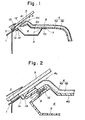
- Figs. 1 to 4 show an embodiment of a defroster structure according to the present invention. As shown in Figs. 1 and 2, a window shield 3 is bonded by a bonding agent 2 to a cowl 1, and one end 4c of an instrument panel 4 is mounted by fittings (not shown) near the shield 3.
- the instrument panel 4 is formed of a panel body 4a and a safety pad 4b. As understood from Fig. 1, an enclosed space 6 is formed by the inner wall 40 and a tray-section-shaped defroster member 5 under the inner wall 40 in the vicinity of the window shield 3 of the panel body 4a.
- the defroster member 5 is not longitudinally spit, but the upper surface of the defroster member 5 is formed by part of the panel body 4a.
- The- defroster member 5 is mounted on the instrument panel 4 by engaging a flange 5a at the rear side of the defroster member 5 between two positioning and air leakage preventing projections 7 and 7 formed on the inner wall 40 of the panel body 4a and fastening the flange 5a at a plurality of positions by thermal fusion-bonding at 8 to the inner wall 40.
- a recess 9 is formed at the front side of the defroster member 5 in the longitudinal direction of a vehicle, and clamped by a screw 11 to a boss 10 formed at the longitudinal front end of the panel body 4 a of the instrument panel 4.
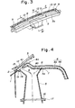
- a plurality of fins 13 (Fig. 3) having approx. 2 mm width for forming the nozzle openings 12, are integrally formed with the front end of the defroster member 5 in the vicinity of the recess 9 in the defroster member 5, and the nozzle openings 12 are formed at the foremost position 41 of the instrument panel 4 in the vicinity of the window shield in the longitudinal direction of the vehicle.
- a seal 14 is interposed between the lower surface of the front end of the defroster member 5 across its entire width and the flange 1a of the cowl 1 as shown in Figs. 1 and 2 so that air does not leak and passes only to the window shield 3
- the nozzle opening 12 may be completely concealed.
- the lower central end of the defroster member 5 is coupled with a heater 17 through a seal 16 to pass air in the direction of arrow A in Fig. 4.
- the nozzle opening of the defroster member is provided at the instrument panel near the window shield to thereby increase the rigidity of the panel body of the instrument panel to eliminate thermal deformation, and to eliminate a garnish for the defroster member, thereby obviating the aligning work of the garnish and to further eliminate the reflection on the window to thus improve the visual field and to allow the nozzle opening of the defroster member to be hardly visible, thereby improving the external appearance and increasing the degree of freedom of design.
Landscapes
- Engineering & Computer Science (AREA)
- Mechanical Engineering (AREA)
- Physics & Mathematics (AREA)
- Thermal Sciences (AREA)
- Instrument Panels (AREA)
Applications Claiming Priority (2)
| Application Number | Priority Date | Filing Date | Title |
|---|---|---|---|
| JP1985090756U JPH0410137Y2 (de) | 1985-06-14 | 1985-06-14 | |
| JP90756/85 | 1985-06-14 |
Publications (3)
| Publication Number | Publication Date |
|---|---|
| EP0206684A2 true EP0206684A2 (de) | 1986-12-30 |
| EP0206684A3 EP0206684A3 (en) | 1987-08-19 |
| EP0206684B1 EP0206684B1 (de) | 1990-12-05 |
Family
ID=14007447
Family Applications (1)
| Application Number | Title | Priority Date | Filing Date |
|---|---|---|---|
| EP86304563A Expired EP0206684B1 (de) | 1985-06-14 | 1986-06-13 | Konstruktion zur Entfrostung von Fahrzeugen |
Country Status (4)
| Country | Link |
|---|---|
| US (1) | US4693416A (de) |
| EP (1) | EP0206684B1 (de) |
| JP (1) | JPH0410137Y2 (de) |
| DE (1) | DE3675988D1 (de) |
Cited By (2)
| Publication number | Priority date | Publication date | Assignee | Title |
|---|---|---|---|---|
| DE19613363B4 (de) * | 1995-04-13 | 2005-09-01 | Volkswagen Ag | Belüftungsanordnung und Verfahren zum Einbau einer solchen in ein Kraftfahrzeug |
| CN103332117A (zh) * | 2013-07-16 | 2013-10-02 | 安徽江淮汽车股份有限公司 | 一种仪表板和前除霜格栅 |
Families Citing this family (11)
| Publication number | Priority date | Publication date | Assignee | Title |
|---|---|---|---|---|
| USD325250S (en) | 1990-09-27 | 1992-04-07 | Atwood Industries, Inc. | Vehicle windshield defroster |
| US5062351A (en) * | 1990-09-27 | 1991-11-05 | Atwood Industries, Inc. | Air diffuser for a motor vehicle |
| US5131886A (en) * | 1991-07-15 | 1992-07-21 | Haustein Norman E | Heated air delivery system for vehicles |
| GB9423776D0 (en) * | 1994-11-25 | 1995-01-11 | Acg Deutschland Gmbh | Dashboard assembly |
| DE10140700C2 (de) * | 2001-08-24 | 2003-10-02 | Siemens Ag | Kraftfahrzeug |
| KR100613708B1 (ko) * | 2004-08-17 | 2006-08-21 | 현대모비스 주식회사 | 인스트루먼트 패널 일체형 디프로스터 덕트 |
| US8109812B2 (en) * | 2007-12-14 | 2012-02-07 | Toyota Motor Engineering & Manufacturing North America, Inc. | Motor vehicle instrument panel assembly having a conduit with a gasket support lip |
| US8591299B2 (en) | 2010-03-31 | 2013-11-26 | Denso International America, Inc. | Windshield de-icing duct system |
| JP6105338B2 (ja) * | 2013-03-14 | 2017-03-29 | ダイキョーニシカワ株式会社 | インストルメントパネル |
| JP7249136B2 (ja) * | 2018-12-05 | 2023-03-30 | 豊和化成株式会社 | レジスタ用フィン |
| CN110877528A (zh) * | 2019-09-26 | 2020-03-13 | 江苏彦圣科技有限公司 | 一种环保智能汽车用仪表盘 |
Citations (2)
| Publication number | Priority date | Publication date | Assignee | Title |
|---|---|---|---|---|
| JPS6064962A (ja) | 1983-09-21 | 1985-04-13 | Nissan Chem Ind Ltd | 2−(β−アリル−β−ヒドロキシエチル)ジヒドロピリジン誘導体およびその製造法 |
| JPS61179013U (de) | 1985-04-29 | 1986-11-08 |
Family Cites Families (7)
| Publication number | Priority date | Publication date | Assignee | Title |
|---|---|---|---|---|
| DE743639C (de) * | 1940-09-10 | 1943-12-30 | Freiherr Reinhard Koenig Fachs | Einrichtung zur Belueftung des Innenraumes und der Windschutzscheibe von Fahrzeugen |
| US2779067A (en) * | 1954-09-17 | 1957-01-29 | Gordon W Stanley | Defrosting attachment for windshields |
| DE1188458B (de) * | 1961-11-02 | 1965-03-04 | Volkswagenwerk Ag | Luftsammelkasten fuer Frischluftbelueftung von Kraftfahrzeugen |
| FR1387157A (fr) * | 1963-12-04 | 1965-01-29 | Renault | Dispositif de climatisation pour véhicules automobiles |
| US4105246A (en) * | 1977-06-20 | 1978-08-08 | Trumbull Gerald M | Multi-purpose dashboard attachment |
| JPS5914267Y2 (ja) * | 1979-06-27 | 1984-04-26 | 本田技研工業株式会社 | 車輛のインストルメントパネル装置 |
| DE3339892A1 (de) * | 1983-11-04 | 1985-05-23 | Adam Opel AG, 6090 Rüsselsheim | Defrosteranlage fuer ein kraftfahrzeug |
-
1985
- 1985-06-14 JP JP1985090756U patent/JPH0410137Y2/ja not_active Expired
-
1986
- 1986-06-12 US US06/873,523 patent/US4693416A/en not_active Expired - Fee Related
- 1986-06-13 DE DE8686304563T patent/DE3675988D1/de not_active Expired - Lifetime
- 1986-06-13 EP EP86304563A patent/EP0206684B1/de not_active Expired
Patent Citations (2)
| Publication number | Priority date | Publication date | Assignee | Title |
|---|---|---|---|---|
| JPS6064962A (ja) | 1983-09-21 | 1985-04-13 | Nissan Chem Ind Ltd | 2−(β−アリル−β−ヒドロキシエチル)ジヒドロピリジン誘導体およびその製造法 |
| JPS61179013U (de) | 1985-04-29 | 1986-11-08 |
Cited By (3)
| Publication number | Priority date | Publication date | Assignee | Title |
|---|---|---|---|---|
| DE19613363B4 (de) * | 1995-04-13 | 2005-09-01 | Volkswagen Ag | Belüftungsanordnung und Verfahren zum Einbau einer solchen in ein Kraftfahrzeug |
| CN103332117A (zh) * | 2013-07-16 | 2013-10-02 | 安徽江淮汽车股份有限公司 | 一种仪表板和前除霜格栅 |
| CN103332117B (zh) * | 2013-07-16 | 2015-08-12 | 安徽江淮汽车股份有限公司 | 一种仪表板和前除霜格栅 |
Also Published As
| Publication number | Publication date |
|---|---|
| JPH0410137Y2 (de) | 1992-03-12 |
| DE3675988D1 (de) | 1991-01-17 |
| US4693416A (en) | 1987-09-15 |
| EP0206684A3 (en) | 1987-08-19 |
| JPS61205849U (de) | 1986-12-25 |
| EP0206684B1 (de) | 1990-12-05 |
Similar Documents
| Publication | Publication Date | Title |
|---|---|---|
| EP0206684A2 (de) | Konstruktion zur Entfrostung von Fahrzeugen | |
| US4679845A (en) | Motor vehicle windshield cowl plate | |
| US6273495B1 (en) | Plastic cross beam assembly for a vehicle having integrally formed duct connectors | |
| EP1170166B1 (de) | Armaturenbrett- Befestigungsanordnung | |
| US7258383B2 (en) | Vehicle body | |
| EP2108569A1 (de) | Hintere plattenstruktur eines automobils | |
| US5915767A (en) | Bumper side supporting structure | |
| US4475614A (en) | Combination meter cover construction | |
| CN217259529U (zh) | 一种隐藏式密封结构、车门及车辆 | |
| KR910009457B1 (ko) | 차량용 상부제동등 | |
| EP0989005B1 (de) | Baugruppe mit einem Defrost-Luftkanal | |
| US4771679A (en) | Air box construction for automotive vehicles | |
| US5558423A (en) | Headlights for motor vehicles | |
| US10654526B2 (en) | Vehicle body structure | |
| JPH08282401A (ja) | カウル部の遮音構造 | |
| GB2304085A (en) | A vehicle bonnet and engine compartment air flow arrangement | |
| US20250033577A1 (en) | Structure of a quadrant cover | |
| EP1174316B1 (de) | Montageanordnung für eine Waschdüse | |
| JPS5934965A (ja) | ウオツシヤ液供給構造 | |
| JP2592408Y2 (ja) | 車両用インストルメントパネルの取付構造 | |
| JPH02246880A (ja) | 自動車用エアボックス構造 | |
| JPS6242857Y2 (de) | ||
| JP3721816B2 (ja) | デフロスタノズル取付構造 | |
| JP3865177B2 (ja) | 樹脂部品の構造 | |
| KR950010167Y1 (ko) | 자동차의 옆부분차체구조 |
Legal Events
| Date | Code | Title | Description |
|---|---|---|---|
| PUAI | Public reference made under article 153(3) epc to a published international application that has entered the european phase |
Free format text: ORIGINAL CODE: 0009012 |
|
| AK | Designated contracting states |
Kind code of ref document: A2 Designated state(s): DE FR GB |
|
| PUAL | Search report despatched |
Free format text: ORIGINAL CODE: 0009013 |
|
| AK | Designated contracting states |
Kind code of ref document: A3 Designated state(s): DE FR GB |
|
| 17P | Request for examination filed |
Effective date: 19880217 |
|
| 17Q | First examination report despatched |
Effective date: 19891117 |
|
| GRAA | (expected) grant |
Free format text: ORIGINAL CODE: 0009210 |
|
| AK | Designated contracting states |
Kind code of ref document: B1 Designated state(s): DE FR GB |
|
| ET | Fr: translation filed | ||
| REF | Corresponds to: |
Ref document number: 3675988 Country of ref document: DE Date of ref document: 19910117 |
|
| PLBI | Opposition filed |
Free format text: ORIGINAL CODE: 0009260 |
|
| PLBI | Opposition filed |
Free format text: ORIGINAL CODE: 0009260 |
|
| 26 | Opposition filed |
Opponent name: AUDI AG Effective date: 19910802 |
|
| 26 | Opposition filed |
Opponent name: MERCEDES- BENZ AG Effective date: 19910904 Opponent name: AUDI AG Effective date: 19910802 |
|
| PLAB | Opposition data, opponent's data or that of the opponent's representative modified |
Free format text: ORIGINAL CODE: 0009299OPPO |
|
| R26 | Opposition filed (corrected) |
Opponent name: AUDI AG * 910904 MERCEDES- BENZ AG Effective date: 19910802 |
|
| PLBN | Opposition rejected |
Free format text: ORIGINAL CODE: 0009273 |
|
| STAA | Information on the status of an ep patent application or granted ep patent |
Free format text: STATUS: OPPOSITION REJECTED |
|
| 27O | Opposition rejected |
Effective date: 19931029 |
|
| REG | Reference to a national code |
Ref country code: GB Ref legal event code: 746 Effective date: 19950807 |
|
| REG | Reference to a national code |
Ref country code: FR Ref legal event code: D6 |
|
| PGFP | Annual fee paid to national office [announced via postgrant information from national office to epo] |
Ref country code: GB Payment date: 19960604 Year of fee payment: 11 |
|
| PGFP | Annual fee paid to national office [announced via postgrant information from national office to epo] |
Ref country code: FR Payment date: 19960611 Year of fee payment: 11 |
|
| PGFP | Annual fee paid to national office [announced via postgrant information from national office to epo] |
Ref country code: DE Payment date: 19960612 Year of fee payment: 11 |
|
| PG25 | Lapsed in a contracting state [announced via postgrant information from national office to epo] |
Ref country code: GB Free format text: LAPSE BECAUSE OF NON-PAYMENT OF DUE FEES Effective date: 19970613 |
|
| GBPC | Gb: european patent ceased through non-payment of renewal fee |
Effective date: 19970613 |
|
| PG25 | Lapsed in a contracting state [announced via postgrant information from national office to epo] |
Ref country code: FR Free format text: LAPSE BECAUSE OF NON-PAYMENT OF DUE FEES Effective date: 19980227 |
|
| PG25 | Lapsed in a contracting state [announced via postgrant information from national office to epo] |
Ref country code: DE Free format text: LAPSE BECAUSE OF NON-PAYMENT OF DUE FEES Effective date: 19980303 |
|
| REG | Reference to a national code |
Ref country code: FR Ref legal event code: ST |
|
| REG | Reference to a national code |
Ref country code: FR Ref legal event code: ST |