EP0206684A2 - Defroster structure for vehicle - Google Patents
Defroster structure for vehicle Download PDFInfo
- Publication number
- EP0206684A2 EP0206684A2 EP86304563A EP86304563A EP0206684A2 EP 0206684 A2 EP0206684 A2 EP 0206684A2 EP 86304563 A EP86304563 A EP 86304563A EP 86304563 A EP86304563 A EP 86304563A EP 0206684 A2 EP0206684 A2 EP 0206684A2
- Authority
- EP
- European Patent Office
- Prior art keywords
- defroster
- instrument panel
- window shield
- vicinity
- nozzle opening
- Prior art date
- Legal status (The legal status is an assumption and is not a legal conclusion. Google has not performed a legal analysis and makes no representation as to the accuracy of the status listed.)
- Granted
Links
Images


Classifications
-
- B—PERFORMING OPERATIONS; TRANSPORTING
- B60—VEHICLES IN GENERAL
- B60H—ARRANGEMENTS OF HEATING, COOLING, VENTILATING OR OTHER AIR-TREATING DEVICES SPECIALLY ADAPTED FOR PASSENGER OR GOODS SPACES OF VEHICLES
- B60H1/00—Heating, cooling or ventilating devices
- B60H1/24—Ventilating devices where the heating or cooling is irrelevant
- B60H1/241—Ventilating devices where the heating or cooling is irrelevant characterised by the location of ventilation devices in the vehicle
- B60H1/242—Ventilating devices where the heating or cooling is irrelevant characterised by the location of ventilation devices in the vehicle located in the front area
-
- B—PERFORMING OPERATIONS; TRANSPORTING
- B60—VEHICLES IN GENERAL
- B60S—SERVICING, CLEANING, REPAIRING, SUPPORTING, LIFTING, OR MANOEUVRING OF VEHICLES, NOT OTHERWISE PROVIDED FOR
- B60S1/00—Cleaning of vehicles
- B60S1/02—Cleaning windscreens, windows or optical devices
- B60S1/54—Cleaning windscreens, windows or optical devices using gas, e.g. hot air
Definitions
- the present invention relates to a defroster structure for a vehicle.
- a nozzle opening 12 of a defroster 5 b is formed at the upper surface 42 of an instrument panel 4, the defroster 5b being formed as a split structure in which a front defroster portion 50 and a rear defroster portion 51 are longitudinally bonded together, and the defroster 6b is fastened by a screw B to a cowl bracket 18.
- FIG. 8 Another conventional defroster structure is shown in Fig. 8, in a defroster device in which a member for coupling a cowl reinforcement member 19 spot or arc welded to the cowl 1 with a front pillar is proviaed, the defroster 5c is provided near the cowl reinforcement member 19, and the nozzle opening 12 of the defroster 5c is mounted near the window shield of the instrument panel 4.
- the inward side wall 19a of the cowl reinforcement member 19 is surrounded by the defroster 5c to form an enclosed space 6
- a defroster garnish 20 formed with the nozzle opening 12 is integrally formed with the defroster 5c, and the garnish 20 is mounted near the window shield 3 of the instrument panel 4.
- an object of the present invention is to provide an improved defroster structure for a vehicie which eliminates or minimizes the above-mentioned drawbacks and disadvantages and provides a defroster nozzle opening at an instrument panel adjacent the window shield.
- a defroster structure for a vehicle having a defroster member provided in the vicinity of a cowl for a window shield, and a nozzle opening of the defroster member mounted in the vicinity of a window shield oj an instrument panel comprising an enclosed space formed by surrounding the panel body of the instrument panel in the vicinity of the window shield at the inner side wall thereof by a tray-section-shaped defroster member, a plurality of fins being integrally formed with the tray-shaped defroster member for forming a nozzle opening, the nozzle opening being proviaed at the foremost position in the longitudinal direction of a vehicle of the instrument panel in the vicinity of the window shield.
- the inner side wall of the panel body of the instrument panel in the vicinity of the window shield aefines an enclosed space together with the tray-shaped defroster member integrally formed with a plurality of fins for forming the nozzle opening tnereof, and the nozzle opening of the defroster member is disposed on the instrument panel in the vicinity of the window shield.
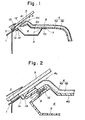
- Figs. 1 to 4 show an embodiment of a defroster structure according to the present invention. As shown in Figs. 1 and 2, a window shield 3 is bonded by a bonding agent 2 to a cowl 1, and one end 4c of an instrument panel 4 is mounted by fittings (not shown) near the shield 3.
- the instrument panel 4 is formed of a panel body 4a and a safety pad 4b. As understood from Fig. 1, an enclosed space 6 is formed by the inner wall 40 and a tray-section-shaped defroster member 5 under the inner wall 40 in the vicinity of the window shield 3 of the panel body 4a.
- the defroster member 5 is not longitudinally spit, but the upper surface of the defroster member 5 is formed by part of the panel body 4a.
- The- defroster member 5 is mounted on the instrument panel 4 by engaging a flange 5a at the rear side of the defroster member 5 between two positioning and air leakage preventing projections 7 and 7 formed on the inner wall 40 of the panel body 4a and fastening the flange 5a at a plurality of positions by thermal fusion-bonding at 8 to the inner wall 40.
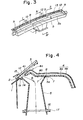
- a recess 9 is formed at the front side of the defroster member 5 in the longitudinal direction of a vehicle, and clamped by a screw 11 to a boss 10 formed at the longitudinal front end of the panel body 4 a of the instrument panel 4.
- a plurality of fins 13 (Fig. 3) having approx. 2 mm width for forming the nozzle openings 12, are integrally formed with the front end of the defroster member 5 in the vicinity of the recess 9 in the defroster member 5, and the nozzle openings 12 are formed at the foremost position 41 of the instrument panel 4 in the vicinity of the window shield in the longitudinal direction of the vehicle.
- a seal 14 is interposed between the lower surface of the front end of the defroster member 5 across its entire width and the flange 1a of the cowl 1 as shown in Figs. 1 and 2 so that air does not leak and passes only to the window shield 3
- the nozzle opening 12 may be completely concealed.
- the lower central end of the defroster member 5 is coupled with a heater 17 through a seal 16 to pass air in the direction of arrow A in Fig. 4.
- the nozzle opening of the defroster member is provided at the instrument panel near the window shield to thereby increase the rigidity of the panel body of the instrument panel to eliminate thermal deformation, and to eliminate a garnish for the defroster member, thereby obviating the aligning work of the garnish and to further eliminate the reflection on the window to thus improve the visual field and to allow the nozzle opening of the defroster member to be hardly visible, thereby improving the external appearance and increasing the degree of freedom of design.
Landscapes
- Engineering & Computer Science (AREA)
- Mechanical Engineering (AREA)
- Physics & Mathematics (AREA)
- Thermal Sciences (AREA)
- Instrument Panels (AREA)
Abstract
Description
- The present invention relates to a defroster structure for a vehicle.
- In a conventional defroster structure, as shown in Figs. 5 to 7, a nozzle opening 12 of a
defroster 5b is formed at theupper surface 42 of aninstrument panel 4, thedefroster 5b being formed as a split structure in which afront defroster portion 50 and arear defroster portion 51 are longitudinally bonded together, and the defroster 6b is fastened by a screw B to acowl bracket 18. - Another conventional defroster structure is shown in Fig. 8, in a defroster device in which a member for coupling a
cowl reinforcement member 19 spot or arc welded to the cowl 1 with a front pillar is proviaed, thedefroster 5c is provided near thecowl reinforcement member 19, and the nozzle opening 12 of thedefroster 5c is mounted near the window shield of theinstrument panel 4. Theinward side wall 19a of thecowl reinforcement member 19 is surrounded by thedefroster 5c to form an enclosedspace 6, adefroster garnish 20 formed with thenozzle opening 12 is integrally formed with thedefroster 5c, and thegarnish 20 is mounted near thewindow shield 3 of theinstrument panel 4. - In the conventional example shown in Figs. 5 to 7, there are the following drawbacks and disadvantages:-
- (i) The nozzle opening 12 of the
defroster 5b provided on theupper surface 42 of theinstrument panel 4 adversely affects the external appearance of the upper surface of the - imatument panel.
- (11) The nozzle opening 12 of the
defroster 5b reflected in thewindow shield 3 during driving to possibly disturb the field of vision. - (iii) In order to improve the external appearance of the nozzle opening 12 of the
defroster 5b, parts of agarnish 21 needing coating increase in number, and thegarnish 21 may thermally deform. Further, a large amount of labor is required to align agap 22 between theinstrument panel 4 and asafety pad 4b or to precisely decide the size of the engagesportion 23 of thegarnish 21, and thegarnish 21 might be frequently removed from theinstrument panel 4. - (iv) Since the
defroster 5b is formed of separately made portions the number of components is increased, thereby increasing the cost and the weight. - (v) When the
panel 4 is molded of resin, a thermal deformation occurs, or the rigidity becomes insufficient, due to the high temperature of solar light entering via holes opened laterally by thenozzle opening 12. - Accordingly, an object of the present invention is to provide an improved defroster structure for a vehicie which eliminates or minimizes the above-mentioned drawbacks and disadvantages and provides a defroster nozzle opening at an instrument panel adjacent the window shield.
- More particularly, according to the present invention, there is provided a defroster structure for a vehicle having a defroster member provided in the vicinity of a cowl for a window shield, and a nozzle opening of the defroster member mounted in the vicinity of a window shield oj an instrument panel comprising an enclosed space formed by surrounding the panel body of the instrument panel in the vicinity of the window shield at the inner side wall thereof by a tray-section-shaped defroster member, a plurality of fins being integrally formed with the tray-shaped defroster member for forming a nozzle opening, the nozzle opening being proviaed at the foremost position in the longitudinal direction of a vehicle of the instrument panel in the vicinity of the window shield.
- According to a defroster structure of the invention described above, the inner side wall of the panel body of the instrument panel in the vicinity of the window shield aefines an enclosed space together with the tray-shaped defroster member integrally formed with a plurality of fins for forming the nozzle opening tnereof, and the nozzle opening of the defroster member is disposed on the instrument panel in the vicinity of the window shield.
- These and other objects and features will become more apparent from the following description of the preferred embodiments of the present invention when read in connection with the accompanying drawings, in which:-
- Fig. 1 is a sectional view of an embodiment of a defroster structure according to the present invention taken along the line I - I in Fig. 3;
- Fig. 2 is a sectional view taken along the line II - Il in Fig. 3;
- Fig. 3 is a perspective view of the tray-shaped defroster member of the embodiment of the invention;
- Pag. 4 is a sectional view taken along the line-IV - IV in Fig. 3;
- Fig. 5 is a sectional view of a conventional defroster structure taken along the ling V - V in Fig. 6;
- Fig. 6 is a perspective view of the conventional defroster structure,
- Fig. 7 is a sectional view taken along the line VII - VII in Fig. 6; and
- Fig. 8 is a sectional view of the other conventional defroster structure.
- Embodiments of the present invention will be described in more detail with reference to the accompanying drawings.
- Figs. 1 to 4 show an embodiment of a defroster structure according to the present invention. As shown in Figs. 1 and 2, a
window shield 3 is bonded by abonding agent 2 to a cowl 1, and oneend 4c of aninstrument panel 4 is mounted by fittings (not shown) near theshield 3. - The
instrument panel 4 is formed of apanel body 4a and asafety pad 4b. As understood from Fig. 1, an enclosedspace 6 is formed by theinner wall 40 and a tray-section-shaped defroster member 5 under theinner wall 40 in the vicinity of thewindow shield 3 of thepanel body 4a. - More specifically, the
defroster member 5 is not longitudinally spit, but the upper surface of thedefroster member 5 is formed by part of thepanel body 4a. - The-
defroster member 5 is mounted on theinstrument panel 4 by engaging aflange 5a at the rear side of thedefroster member 5 between two positioning and airleakage preventing projections inner wall 40 of thepanel body 4a and fastening theflange 5a at a plurality of positions by thermal fusion-bonding at 8 to theinner wall 40. - As understood from Fig. 2, a
recess 9 is formed at the front side of thedefroster member 5 in the longitudinal direction of a vehicle, and clamped by a screw 11 to aboss 10 formed at the longitudinal front end of thepanel body 4 a of theinstrument panel 4. - Further,a plurality of fins 13 (Fig. 3) having approx. 2 mm width for forming the
nozzle openings 12, are integrally formed with the front end of thedefroster member 5 in the vicinity of therecess 9 in thedefroster member 5, and thenozzle openings 12 are formed at theforemost position 41 of theinstrument panel 4 in the vicinity of the window shield in the longitudinal direction of the vehicle. In order to diffuse air along thewindow shield 3 as designated by an arrow A in Fig. 1 from the nozzle opening 12, aseal 14 is interposed between the lower surface of the front end of thedefroster member 5 across its entire width and the flange 1a of the cowl 1 as shown in Figs. 1 and 2 so that air does not leak and passes only to thewindow shield 3 - As shown in Fig. 1, when a
paint layer 15 is coated on thewindow shield 3 opposite thenozzle openings 12 inside the compartment, thenozzle opening 12 may be completely concealed. - As further shown in Fig. 4, the lower central end of the
defroster member 5 is coupled with aheater 17 through aseal 16 to pass air in the direction of arrow A in Fig. 4. - According to the present invention as described above, the nozzle opening of the defroster member is provided at the instrument panel near the window shield to thereby increase the rigidity of the panel body of the instrument panel to eliminate thermal deformation, and to eliminate a garnish for the defroster member, thereby obviating the aligning work of the garnish and to further eliminate the reflection on the window to thus improve the visual field and to allow the nozzle opening of the defroster member to be hardly visible, thereby improving the external appearance and increasing the degree of freedom of design.
Claims (6)
Applications Claiming Priority (2)
| Application Number | Priority Date | Filing Date | Title |
|---|---|---|---|
| JP90756/85 | 1985-06-14 | ||
| JP1985090756U JPH0410137Y2 (en) | 1985-06-14 | 1985-06-14 |
Publications (3)
| Publication Number | Publication Date |
|---|---|
| EP0206684A2 true EP0206684A2 (en) | 1986-12-30 |
| EP0206684A3 EP0206684A3 (en) | 1987-08-19 |
| EP0206684B1 EP0206684B1 (en) | 1990-12-05 |
Family
ID=14007447
Family Applications (1)
| Application Number | Title | Priority Date | Filing Date |
|---|---|---|---|
| EP86304563A Expired EP0206684B1 (en) | 1985-06-14 | 1986-06-13 | Defroster structure for vehicle |
Country Status (4)
| Country | Link |
|---|---|
| US (1) | US4693416A (en) |
| EP (1) | EP0206684B1 (en) |
| JP (1) | JPH0410137Y2 (en) |
| DE (1) | DE3675988D1 (en) |
Cited By (2)
| Publication number | Priority date | Publication date | Assignee | Title |
|---|---|---|---|---|
| DE19613363B4 (en) * | 1995-04-13 | 2005-09-01 | Volkswagen Ag | Ventilation arrangement and method for installing such in a motor vehicle |
| CN103332117A (en) * | 2013-07-16 | 2013-10-02 | 安徽江淮汽车股份有限公司 | Dash board and front defrosting grid |
Families Citing this family (11)
| Publication number | Priority date | Publication date | Assignee | Title |
|---|---|---|---|---|
| US5062351A (en) * | 1990-09-27 | 1991-11-05 | Atwood Industries, Inc. | Air diffuser for a motor vehicle |
| USD325250S (en) | 1990-09-27 | 1992-04-07 | Atwood Industries, Inc. | Vehicle windshield defroster |
| US5131886A (en) * | 1991-07-15 | 1992-07-21 | Haustein Norman E | Heated air delivery system for vehicles |
| GB9423776D0 (en) * | 1994-11-25 | 1995-01-11 | Acg Deutschland Gmbh | Dashboard assembly |
| DE10140700C2 (en) * | 2001-08-24 | 2003-10-02 | Siemens Ag | motor vehicle |
| KR100613708B1 (en) * | 2004-08-17 | 2006-08-21 | 현대모비스 주식회사 | Instrument panel integrated defroster duct |
| US8109812B2 (en) * | 2007-12-14 | 2012-02-07 | Toyota Motor Engineering & Manufacturing North America, Inc. | Motor vehicle instrument panel assembly having a conduit with a gasket support lip |
| US8591299B2 (en) | 2010-03-31 | 2013-11-26 | Denso International America, Inc. | Windshield de-icing duct system |
| JP6105338B2 (en) * | 2013-03-14 | 2017-03-29 | ダイキョーニシカワ株式会社 | instrument panel |
| JP7249136B2 (en) * | 2018-12-05 | 2023-03-30 | 豊和化成株式会社 | Fins for resistors |
| CN110877528A (en) * | 2019-09-26 | 2020-03-13 | 江苏彦圣科技有限公司 | Environment-friendly instrument panel for intelligent automobile |
Citations (2)
| Publication number | Priority date | Publication date | Assignee | Title |
|---|---|---|---|---|
| JPS6064962A (en) | 1983-09-21 | 1985-04-13 | Nissan Chem Ind Ltd | 2-(beta-aryl-beta-hydroxyethyl)dihydropyridine derivative and its preparation |
| JPS61179013U (en) | 1985-04-29 | 1986-11-08 |
Family Cites Families (7)
| Publication number | Priority date | Publication date | Assignee | Title |
|---|---|---|---|---|
| DE743639C (en) * | 1940-09-10 | 1943-12-30 | Freiherr Reinhard Koenig Fachs | Device for ventilation of the interior and the windshield of vehicles |
| US2779067A (en) * | 1954-09-17 | 1957-01-29 | Gordon W Stanley | Defrosting attachment for windshields |
| DE1188458B (en) * | 1961-11-02 | 1965-03-04 | Volkswagenwerk Ag | Air collecting box for fresh air ventilation of motor vehicles |
| FR1387157A (en) * | 1963-12-04 | 1965-01-29 | Renault | Air conditioning system for motor vehicles |
| US4105246A (en) * | 1977-06-20 | 1978-08-08 | Trumbull Gerald M | Multi-purpose dashboard attachment |
| JPS5914267Y2 (en) * | 1979-06-27 | 1984-04-26 | 本田技研工業株式会社 | Vehicle instrument panel device |
| DE3339892A1 (en) * | 1983-11-04 | 1985-05-23 | Adam Opel AG, 6090 Rüsselsheim | DEFROSTER SYSTEM FOR A MOTOR VEHICLE |
-
1985
- 1985-06-14 JP JP1985090756U patent/JPH0410137Y2/ja not_active Expired
-
1986
- 1986-06-12 US US06/873,523 patent/US4693416A/en not_active Expired - Fee Related
- 1986-06-13 EP EP86304563A patent/EP0206684B1/en not_active Expired
- 1986-06-13 DE DE8686304563T patent/DE3675988D1/en not_active Expired - Lifetime
Patent Citations (2)
| Publication number | Priority date | Publication date | Assignee | Title |
|---|---|---|---|---|
| JPS6064962A (en) | 1983-09-21 | 1985-04-13 | Nissan Chem Ind Ltd | 2-(beta-aryl-beta-hydroxyethyl)dihydropyridine derivative and its preparation |
| JPS61179013U (en) | 1985-04-29 | 1986-11-08 |
Cited By (3)
| Publication number | Priority date | Publication date | Assignee | Title |
|---|---|---|---|---|
| DE19613363B4 (en) * | 1995-04-13 | 2005-09-01 | Volkswagen Ag | Ventilation arrangement and method for installing such in a motor vehicle |
| CN103332117A (en) * | 2013-07-16 | 2013-10-02 | 安徽江淮汽车股份有限公司 | Dash board and front defrosting grid |
| CN103332117B (en) * | 2013-07-16 | 2015-08-12 | 安徽江淮汽车股份有限公司 | A kind of instrument carrier panel and front defrosting grid |
Also Published As
| Publication number | Publication date |
|---|---|
| US4693416A (en) | 1987-09-15 |
| EP0206684A3 (en) | 1987-08-19 |
| JPH0410137Y2 (en) | 1992-03-12 |
| DE3675988D1 (en) | 1991-01-17 |
| JPS61205849U (en) | 1986-12-25 |
| EP0206684B1 (en) | 1990-12-05 |
Similar Documents
| Publication | Publication Date | Title |
|---|---|---|
| EP0206684A2 (en) | Defroster structure for vehicle | |
| US4679845A (en) | Motor vehicle windshield cowl plate | |
| US6273495B1 (en) | Plastic cross beam assembly for a vehicle having integrally formed duct connectors | |
| EP1170166B1 (en) | Instrument panel mounting structure | |
| US7258383B2 (en) | Vehicle body | |
| EP2108569A1 (en) | Rear panel structure of automobile | |
| US5915767A (en) | Bumper side supporting structure | |
| US4475614A (en) | Combination meter cover construction | |
| KR910009457B1 (en) | High-mounted stoplight for motor vehicle | |
| US5558423A (en) | Headlights for motor vehicles | |
| US20220297507A1 (en) | Defroster structure | |
| US10654526B2 (en) | Vehicle body structure | |
| JPH08282401A (en) | Sound insulation structure of the cowl | |
| GB2304085A (en) | A vehicle bonnet and engine compartment air flow arrangement | |
| US20250033577A1 (en) | Structure of a quadrant cover | |
| EP1174316B1 (en) | Mounting structure for washer nozzle | |
| EP4534366A1 (en) | Cleaning device | |
| JP2527235B2 (en) | Bumper fascia mounting structure | |
| JPS5934965A (en) | Feeding structure of washer liquid | |
| JP2592408Y2 (en) | Installation structure of vehicle instrument panel | |
| JPH02246880A (en) | Air box structure for automobile | |
| JPS6242857Y2 (en) | ||
| JP3721816B2 (en) | Defroster nozzle mounting structure | |
| JP3865177B2 (en) | Structure of resin parts | |
| KR950010167Y1 (en) | Side structure of car |
Legal Events
| Date | Code | Title | Description |
|---|---|---|---|
| PUAI | Public reference made under article 153(3) epc to a published international application that has entered the european phase |
Free format text: ORIGINAL CODE: 0009012 |
|
| AK | Designated contracting states |
Kind code of ref document: A2 Designated state(s): DE FR GB |
|
| PUAL | Search report despatched |
Free format text: ORIGINAL CODE: 0009013 |
|
| AK | Designated contracting states |
Kind code of ref document: A3 Designated state(s): DE FR GB |
|
| 17P | Request for examination filed |
Effective date: 19880217 |
|
| 17Q | First examination report despatched |
Effective date: 19891117 |
|
| GRAA | (expected) grant |
Free format text: ORIGINAL CODE: 0009210 |
|
| AK | Designated contracting states |
Kind code of ref document: B1 Designated state(s): DE FR GB |
|
| ET | Fr: translation filed | ||
| REF | Corresponds to: |
Ref document number: 3675988 Country of ref document: DE Date of ref document: 19910117 |
|
| PLBI | Opposition filed |
Free format text: ORIGINAL CODE: 0009260 |
|
| PLBI | Opposition filed |
Free format text: ORIGINAL CODE: 0009260 |
|
| 26 | Opposition filed |
Opponent name: AUDI AG Effective date: 19910802 |
|
| 26 | Opposition filed |
Opponent name: MERCEDES- BENZ AG Effective date: 19910904 Opponent name: AUDI AG Effective date: 19910802 |
|
| PLAB | Opposition data, opponent's data or that of the opponent's representative modified |
Free format text: ORIGINAL CODE: 0009299OPPO |
|
| R26 | Opposition filed (corrected) |
Opponent name: AUDI AG * 910904 MERCEDES- BENZ AG Effective date: 19910802 |
|
| PLBN | Opposition rejected |
Free format text: ORIGINAL CODE: 0009273 |
|
| STAA | Information on the status of an ep patent application or granted ep patent |
Free format text: STATUS: OPPOSITION REJECTED |
|
| 27O | Opposition rejected |
Effective date: 19931029 |
|
| REG | Reference to a national code |
Ref country code: GB Ref legal event code: 746 Effective date: 19950807 |
|
| REG | Reference to a national code |
Ref country code: FR Ref legal event code: D6 |
|
| PGFP | Annual fee paid to national office [announced via postgrant information from national office to epo] |
Ref country code: GB Payment date: 19960604 Year of fee payment: 11 |
|
| PGFP | Annual fee paid to national office [announced via postgrant information from national office to epo] |
Ref country code: FR Payment date: 19960611 Year of fee payment: 11 |
|
| PGFP | Annual fee paid to national office [announced via postgrant information from national office to epo] |
Ref country code: DE Payment date: 19960612 Year of fee payment: 11 |
|
| PG25 | Lapsed in a contracting state [announced via postgrant information from national office to epo] |
Ref country code: GB Free format text: LAPSE BECAUSE OF NON-PAYMENT OF DUE FEES Effective date: 19970613 |
|
| GBPC | Gb: european patent ceased through non-payment of renewal fee |
Effective date: 19970613 |
|
| PG25 | Lapsed in a contracting state [announced via postgrant information from national office to epo] |
Ref country code: FR Free format text: LAPSE BECAUSE OF NON-PAYMENT OF DUE FEES Effective date: 19980227 |
|
| PG25 | Lapsed in a contracting state [announced via postgrant information from national office to epo] |
Ref country code: DE Free format text: LAPSE BECAUSE OF NON-PAYMENT OF DUE FEES Effective date: 19980303 |
|
| REG | Reference to a national code |
Ref country code: FR Ref legal event code: ST |
|
| REG | Reference to a national code |
Ref country code: FR Ref legal event code: ST |