EP0202733B1 - Procédé pour appliquer une quantité prédéterminée de catalyseur sur les surfaces intérieures d'un substrat creux - Google Patents
Procédé pour appliquer une quantité prédéterminée de catalyseur sur les surfaces intérieures d'un substrat creux Download PDFInfo
- Publication number
- EP0202733B1 EP0202733B1 EP86301418A EP86301418A EP0202733B1 EP 0202733 B1 EP0202733 B1 EP 0202733B1 EP 86301418 A EP86301418 A EP 86301418A EP 86301418 A EP86301418 A EP 86301418A EP 0202733 B1 EP0202733 B1 EP 0202733B1
- Authority
- EP
- European Patent Office
- Prior art keywords
- substrate
- slurry
- vacuum
- clamp
- dip pan
- Prior art date
- Legal status (The legal status is an assumption and is not a legal conclusion. Google has not performed a legal analysis and makes no representation as to the accuracy of the status listed.)
- Expired - Lifetime
Links
- 239000000758 substrate Substances 0.000 title claims abstract description 297
- 238000000034 method Methods 0.000 title claims abstract description 45
- 230000008569 process Effects 0.000 title claims abstract description 31
- 239000003054 catalyst Substances 0.000 title claims description 35
- 239000002002 slurry Substances 0.000 claims abstract description 181
- 238000000576 coating method Methods 0.000 claims abstract description 38
- 239000011248 coating agent Substances 0.000 claims abstract description 37
- 239000000463 material Substances 0.000 claims abstract description 24
- 238000001035 drying Methods 0.000 claims description 8
- 230000005484 gravity Effects 0.000 claims description 4
- 239000007787 solid Substances 0.000 claims description 4
- 238000013459 approach Methods 0.000 claims description 3
- 238000007654 immersion Methods 0.000 claims description 3
- 238000005303 weighing Methods 0.000 claims description 3
- 239000012530 fluid Substances 0.000 claims description 2
- 239000000725 suspension Substances 0.000 claims description 2
- 238000007789 sealing Methods 0.000 claims 5
- 238000002360 preparation method Methods 0.000 claims 2
- 238000001816 cooling Methods 0.000 claims 1
- 239000004576 sand Substances 0.000 claims 1
- 230000003197 catalytic effect Effects 0.000 abstract description 5
- 238000009826 distribution Methods 0.000 abstract description 4
- 239000010970 precious metal Substances 0.000 abstract description 4
- 239000000919 ceramic Substances 0.000 description 8
- KDLHZDBZIXYQEI-UHFFFAOYSA-N Palladium Chemical compound [Pd] KDLHZDBZIXYQEI-UHFFFAOYSA-N 0.000 description 6
- 239000006255 coating slurry Substances 0.000 description 6
- 238000005470 impregnation Methods 0.000 description 6
- BASFCYQUMIYNBI-UHFFFAOYSA-N platinum Chemical compound [Pt] BASFCYQUMIYNBI-UHFFFAOYSA-N 0.000 description 6
- 238000010276 construction Methods 0.000 description 5
- 238000011068 loading method Methods 0.000 description 5
- 238000004519 manufacturing process Methods 0.000 description 5
- 229910052751 metal Inorganic materials 0.000 description 5
- 239000002184 metal Substances 0.000 description 5
- 239000004033 plastic Substances 0.000 description 4
- 229920003023 plastic Polymers 0.000 description 4
- 229920004943 Delrin® Polymers 0.000 description 3
- PNEYBMLMFCGWSK-UHFFFAOYSA-N aluminium oxide Inorganic materials [O-2].[O-2].[O-2].[Al+3].[Al+3] PNEYBMLMFCGWSK-UHFFFAOYSA-N 0.000 description 3
- 230000007246 mechanism Effects 0.000 description 3
- 229910052763 palladium Inorganic materials 0.000 description 3
- 229910052697 platinum Inorganic materials 0.000 description 3
- 229910052703 rhodium Inorganic materials 0.000 description 3
- 239000010948 rhodium Substances 0.000 description 3
- MHOVAHRLVXNVSD-UHFFFAOYSA-N rhodium atom Chemical compound [Rh] MHOVAHRLVXNVSD-UHFFFAOYSA-N 0.000 description 3
- 238000009736 wetting Methods 0.000 description 3
- XEEYBQQBJWHFJM-UHFFFAOYSA-N Iron Chemical compound [Fe] XEEYBQQBJWHFJM-UHFFFAOYSA-N 0.000 description 2
- PXHVJJICTQNCMI-UHFFFAOYSA-N Nickel Chemical compound [Ni] PXHVJJICTQNCMI-UHFFFAOYSA-N 0.000 description 2
- 241000272171 Scolopacidae Species 0.000 description 2
- 230000008901 benefit Effects 0.000 description 2
- 230000000694 effects Effects 0.000 description 2
- 239000011152 fibreglass Substances 0.000 description 2
- 238000011049 filling Methods 0.000 description 2
- 239000007789 gas Substances 0.000 description 2
- 238000012545 processing Methods 0.000 description 2
- 238000010926 purge Methods 0.000 description 2
- 238000012421 spiking Methods 0.000 description 2
- 230000007480 spreading Effects 0.000 description 2
- 238000003892 spreading Methods 0.000 description 2
- 229910001220 stainless steel Inorganic materials 0.000 description 2
- 239000010935 stainless steel Substances 0.000 description 2
- 239000002699 waste material Substances 0.000 description 2
- XLYOFNOQVPJJNP-UHFFFAOYSA-N water Substances O XLYOFNOQVPJJNP-UHFFFAOYSA-N 0.000 description 2
- VYZAMTAEIAYCRO-UHFFFAOYSA-N Chromium Chemical compound [Cr] VYZAMTAEIAYCRO-UHFFFAOYSA-N 0.000 description 1
- RYGMFSIKBFXOCR-UHFFFAOYSA-N Copper Chemical compound [Cu] RYGMFSIKBFXOCR-UHFFFAOYSA-N 0.000 description 1
- 239000004677 Nylon Substances 0.000 description 1
- 235000014676 Phragmites communis Nutrition 0.000 description 1
- 239000004743 Polypropylene Substances 0.000 description 1
- 239000004793 Polystyrene Substances 0.000 description 1
- KJTLSVCANCCWHF-UHFFFAOYSA-N Ruthenium Chemical compound [Ru] KJTLSVCANCCWHF-UHFFFAOYSA-N 0.000 description 1
- DHKHKXVYLBGOIT-UHFFFAOYSA-N acetaldehyde Diethyl Acetal Natural products CCOC(C)OCC DHKHKXVYLBGOIT-UHFFFAOYSA-N 0.000 description 1
- 125000002777 acetyl group Chemical class [H]C([H])([H])C(*)=O 0.000 description 1
- 230000009471 action Effects 0.000 description 1
- 239000011149 active material Substances 0.000 description 1
- 238000003915 air pollution Methods 0.000 description 1
- 229910000323 aluminium silicate Inorganic materials 0.000 description 1
- HEHRHMRHPUNLIR-UHFFFAOYSA-N aluminum;hydroxy-[hydroxy(oxo)silyl]oxy-oxosilane;lithium Chemical compound [Li].[Al].O[Si](=O)O[Si](O)=O.O[Si](=O)O[Si](O)=O HEHRHMRHPUNLIR-UHFFFAOYSA-N 0.000 description 1
- CNLWCVNCHLKFHK-UHFFFAOYSA-N aluminum;lithium;dioxido(oxo)silane Chemical compound [Li+].[Al+3].[O-][Si]([O-])=O.[O-][Si]([O-])=O CNLWCVNCHLKFHK-UHFFFAOYSA-N 0.000 description 1
- 230000003321 amplification Effects 0.000 description 1
- 239000010953 base metal Substances 0.000 description 1
- 235000013405 beer Nutrition 0.000 description 1
- 230000015572 biosynthetic process Effects 0.000 description 1
- 230000000903 blocking effect Effects 0.000 description 1
- 238000007664 blowing Methods 0.000 description 1
- 210000004556 brain Anatomy 0.000 description 1
- HGAZMNJKRQFZKS-UHFFFAOYSA-N chloroethene;ethenyl acetate Chemical compound ClC=C.CC(=O)OC=C HGAZMNJKRQFZKS-UHFFFAOYSA-N 0.000 description 1
- 229910052804 chromium Inorganic materials 0.000 description 1
- 239000011651 chromium Substances 0.000 description 1
- 238000004140 cleaning Methods 0.000 description 1
- 229910017052 cobalt Inorganic materials 0.000 description 1
- 239000010941 cobalt Substances 0.000 description 1
- GUTLYIVDDKVIGB-UHFFFAOYSA-N cobalt atom Chemical compound [Co] GUTLYIVDDKVIGB-UHFFFAOYSA-N 0.000 description 1
- 239000000498 cooling water Substances 0.000 description 1
- 229910052802 copper Inorganic materials 0.000 description 1
- 239000010949 copper Substances 0.000 description 1
- 229910052878 cordierite Inorganic materials 0.000 description 1
- 239000002178 crystalline material Substances 0.000 description 1
- 230000007812 deficiency Effects 0.000 description 1
- 230000002950 deficient Effects 0.000 description 1
- 238000010586 diagram Methods 0.000 description 1
- JSKIRARMQDRGJZ-UHFFFAOYSA-N dimagnesium dioxido-bis[(1-oxido-3-oxo-2,4,6,8,9-pentaoxa-1,3-disila-5,7-dialuminabicyclo[3.3.1]nonan-7-yl)oxy]silane Chemical compound [Mg++].[Mg++].[O-][Si]([O-])(O[Al]1O[Al]2O[Si](=O)O[Si]([O-])(O1)O2)O[Al]1O[Al]2O[Si](=O)O[Si]([O-])(O1)O2 JSKIRARMQDRGJZ-UHFFFAOYSA-N 0.000 description 1
- KZHJGOXRZJKJNY-UHFFFAOYSA-N dioxosilane;oxo(oxoalumanyloxy)alumane Chemical compound O=[Si]=O.O=[Si]=O.O=[Al]O[Al]=O.O=[Al]O[Al]=O.O=[Al]O[Al]=O KZHJGOXRZJKJNY-UHFFFAOYSA-N 0.000 description 1
- 238000003618 dip coating Methods 0.000 description 1
- 239000006260 foam Substances 0.000 description 1
- 238000010438 heat treatment Methods 0.000 description 1
- 230000006872 improvement Effects 0.000 description 1
- 230000000977 initiatory effect Effects 0.000 description 1
- 238000003780 insertion Methods 0.000 description 1
- 230000037431 insertion Effects 0.000 description 1
- 230000010354 integration Effects 0.000 description 1
- 230000003993 interaction Effects 0.000 description 1
- 229910052742 iron Inorganic materials 0.000 description 1
- 238000002955 isolation Methods 0.000 description 1
- 239000000391 magnesium silicate Substances 0.000 description 1
- 235000012243 magnesium silicates Nutrition 0.000 description 1
- WPBNNNQJVZRUHP-UHFFFAOYSA-L manganese(2+);methyl n-[[2-(methoxycarbonylcarbamothioylamino)phenyl]carbamothioyl]carbamate;n-[2-(sulfidocarbothioylamino)ethyl]carbamodithioate Chemical compound [Mn+2].[S-]C(=S)NCCNC([S-])=S.COC(=O)NC(=S)NC1=CC=CC=C1NC(=S)NC(=O)OC WPBNNNQJVZRUHP-UHFFFAOYSA-L 0.000 description 1
- 229910044991 metal oxide Inorganic materials 0.000 description 1
- 150000004706 metal oxides Chemical class 0.000 description 1
- 150000002739 metals Chemical class 0.000 description 1
- 238000012986 modification Methods 0.000 description 1
- 230000004048 modification Effects 0.000 description 1
- 238000012544 monitoring process Methods 0.000 description 1
- 229910052863 mullite Inorganic materials 0.000 description 1
- 229910052759 nickel Inorganic materials 0.000 description 1
- 229910000510 noble metal Inorganic materials 0.000 description 1
- 230000001473 noxious effect Effects 0.000 description 1
- 238000003199 nucleic acid amplification method Methods 0.000 description 1
- 229920001778 nylon Polymers 0.000 description 1
- 230000000737 periodic effect Effects 0.000 description 1
- 230000002093 peripheral effect Effects 0.000 description 1
- 229910052670 petalite Inorganic materials 0.000 description 1
- -1 polypropylene Polymers 0.000 description 1
- 229920001155 polypropylene Polymers 0.000 description 1
- 229920002223 polystyrene Polymers 0.000 description 1
- 239000004800 polyvinyl chloride Substances 0.000 description 1
- 230000010349 pulsation Effects 0.000 description 1
- 230000003134 recirculating effect Effects 0.000 description 1
- 230000009467 reduction Effects 0.000 description 1
- 239000003870 refractory metal Substances 0.000 description 1
- 239000012858 resilient material Substances 0.000 description 1
- 230000004044 response Effects 0.000 description 1
- 230000000284 resting effect Effects 0.000 description 1
- 229910052707 ruthenium Inorganic materials 0.000 description 1
- 229910052851 sillimanite Inorganic materials 0.000 description 1
- 239000011343 solid material Substances 0.000 description 1
- 229910052642 spodumene Inorganic materials 0.000 description 1
- 239000000126 substance Substances 0.000 description 1
- 238000001771 vacuum deposition Methods 0.000 description 1
- 229910052720 vanadium Inorganic materials 0.000 description 1
- LEONUFNNVUYDNQ-UHFFFAOYSA-N vanadium atom Chemical compound [V] LEONUFNNVUYDNQ-UHFFFAOYSA-N 0.000 description 1
- 230000000007 visual effect Effects 0.000 description 1
- 238000004260 weight control Methods 0.000 description 1
- 229910052845 zircon Inorganic materials 0.000 description 1
- GFQYVLUOOAAOGM-UHFFFAOYSA-N zirconium(iv) silicate Chemical compound [Zr+4].[O-][Si]([O-])([O-])[O-] GFQYVLUOOAAOGM-UHFFFAOYSA-N 0.000 description 1
Images


Classifications
-
- B—PERFORMING OPERATIONS; TRANSPORTING
- B01—PHYSICAL OR CHEMICAL PROCESSES OR APPARATUS IN GENERAL
- B01J—CHEMICAL OR PHYSICAL PROCESSES, e.g. CATALYSIS OR COLLOID CHEMISTRY; THEIR RELEVANT APPARATUS
- B01J37/00—Processes, in general, for preparing catalysts; Processes, in general, for activation of catalysts
- B01J37/02—Impregnation, coating or precipitation
- B01J37/0215—Coating
-
- Y—GENERAL TAGGING OF NEW TECHNOLOGICAL DEVELOPMENTS; GENERAL TAGGING OF CROSS-SECTIONAL TECHNOLOGIES SPANNING OVER SEVERAL SECTIONS OF THE IPC; TECHNICAL SUBJECTS COVERED BY FORMER USPC CROSS-REFERENCE ART COLLECTIONS [XRACs] AND DIGESTS
- Y10—TECHNICAL SUBJECTS COVERED BY FORMER USPC
- Y10S—TECHNICAL SUBJECTS COVERED BY FORMER USPC CROSS-REFERENCE ART COLLECTIONS [XRACs] AND DIGESTS
- Y10S502/00—Catalyst, solid sorbent, or support therefor: product or process of making
- Y10S502/514—Process applicable either to preparing or to regenerating or to rehabilitating catalyst or sorbent
Definitions
- This invention relates to a method and apparatus for the impregnation of ceramic monolithic substrates and, more particularly, to such a method and apparatus which enable the impregnation of the substrate with a predetermined amount of catalyst in an efficient manner and without waste.
- the need to remove or convert the noxious components in vehicular exhaust gases is now well known as a means for overcoming air pollution.
- the present and proposed future requirements for having catalytic exhaust gas converters on motor vehicles are quite well known.
- One form in which the catalyst for the converters is supplied is as catalytically coated rigid skeletal monolithic substrates, or honeycomb-type elements which are generally cylindrical or oval in shape, where there are a multiplicity of longitudinal passageways in each unit in order to provide a high surface area.
- the rigid, monolithic, skeletal substrate structures are typically fabricated from ceramics which comprise refractory crystalline materials such as sillimanite, magnesium silicates, zircon, petalite, spodumene, cordierite, aluminosilicates, mullite, or combinations thereof. Such materials are generally considered to have a porous surface, but to improve the porosity of the surfaces of the skeletal surface, it is generally advisable to provide a highly porous alumina coating over the skeletal structure prior to effecting surface impregnation with a catalytically active material.
- These monolithic, substantially catalytically inactive skeletal substrate members have been described in price art patents, as for example in Keith et al U.S. patent numbers 3,331,787 and 3,565,830, such that it is not deemed necessary to describe them in detail herein.
- the catalytic component will comprise one or more of the noble and base metals and metal oxides of Groups IB, VB, VIIB, and VIII of the Periodic Table, particularly, copper, vanadium, chromium, manganese, iron, cobalt, nickel, platinum, palladium, rhodium, and ruthenium, with one catalytic metal being used singly or in combination with one or more other active metals.
- U.S. 3,948,213 to Hoyer et al discloses a treating chamber for applying a coating slurry to a substrate. The slurry is introduced from the top and flows downwardly through the hollow substrate.
- U.S. 4,038,939 to Hoyer et al discloses a process of impregnating a substrate by immersion within a treating chamber. It utilizes removal arm means which operate to effect a 90-degree turn of each substrate as it is removed from the treating chamber such that its honeycomb passageways are oriented in a generally horizontal manner to enable air blowing and drying of wet elements and to preclude slurry droplets from blocking the passageways.
- slurry is applied to a substrate either by dip coating or by applying a coating charge to the upper end of the substrate. It is mentioned in the patent that it may be advantageous, after the substrate has been purged from one end, to invert the substrate and continue the purge from the opposite end.
- the present invention meets these needs by providing a method and apparatus for vacuum coating ceramic substrate members with a slurry of refractory and/or catalyst metal components wherein precisely controlled, predetermined amounts of the slurry are metered for application to the ceramic monolithic substrate member. This eliminates the need for flooding the member with excess coating material and the previously necessary ancillary steps for removal of the excess coating material from the member. Thus, by using the process and apparatus of the present invention, it is possible to apply a uniform coating of the desired concentration of the refractory and catalyst metal components without the need for external coating removal or internal unplugging of the internal skeletal passageways of the ceramic monolithic substrate.
- a hollow substrate to be treated and having opposed open ends is transferred from a rest position such that one end is lowered into a dip pan into which has been introduced a predetermined amount or charge of slurry material containing the precious metal.
- a vacuum placed on the other end of the substrate draws all of the slurry from the dip pan to coat the lower portion of the substrate.
- the substrate is raised from the dip pan, then rotated, and again lowered so that the other end is fully immersed in another predetermined charge of the slurry and the process is repeated.
- the substrate is raised from the dip pan, rotated to return it to its original orientation, and returned to its starting location.
- the apparatus which serves to acheive the goals of the invention incorporates a number of unique features.
- One of these features is a control system comprised of a computer, sensors, and limit switches to assure that operations are performed on a timely basis and in a proper sequence.
- the tank containing the slurry is preferably fabricated of stainless steel which is plastic or fiberglass lined or coated for ease of flow of the slurry, and has a bottom portion which slopes toward the outlet to assure continuing flow of all of the solid material present in the slurry. Its contents are regularly agitated and its temperature is maintained within acceptable limits.
- Still another feature of the invention is the provision of a dip pan formed with a slurry receiving cavity preferably shaped to freely receive but closely conform to the shape, in cross section, of the substrate to be coated.
- Two different methods of introducing a predetermined charge of slurry into the dip pan are provided by the invention.
- the magnitude of the predetermined charge is based on weight; in the other instance, it is based on volume.
- a particularly critical part of the operation disclosed involves positioning each end of a substrate within the dip pan such that it is immersed in the slurry but spaced a specific distance from the bottom of a cavity formed in the dip pan.
- appropriate sensors detect the end of the substrate which is about to be immersed in the slurry.
- the sensors signal the computer which, in turn, stops movement of the substrate when the end immersed in the slurry is spaced a proper distance above the bottom of the cavity in the dip pan.
- Another feature of the invention resides in providing an appropriate mechanism for rotating the substrate after one end has been coated so as to orient the other end for the same coating procedure.
- Still another feature of the invention resides in providing a vacuum cone which is lowered onto the exposed end of the substrate as the latter is being immersed into the slurry. Immediately prior to the vacuum cone initially engaging the end of the substrate, a low vacuum is applied, first to evacuate the interest of the substrate, then to begin drawing the slurry upwardly, after which high vacuum is applied to complete the coating task. The coating task is completed as to an end of the substrate when all of the slurry in the dip pan has been withdrawn. In this fashion, waste of costly slurry is avoided.
- the substrate is rotated once again to return it to its original orientation. In this manner, the substrate will be properly returned to its original resting place or shelf without concern that it will strike the top of the shelf or drop down onto the shelf.
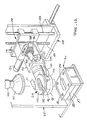
- Figure 1 generally illustrates a system 20 embodying the principles of the present invention.
- the overall process to be disclosed is a semi-automatic one in that the operator of the system must initially place the substrates to be coated into the system manually and remove them after they have been coated. Otherwise, the process requires no operator interaction.
- the operator places a substrate 21 (Figure 13), which is hollow and open at both ends, on a shelf 22 within a substrate clamp 24, then pushes a start button 26 on a control panel 28.
- the substrate is secured by the clamp 24, transferred and lowered into a dip pan 30 which contains a charge of slurry material which is to be drawn up into the substrate.
- An initial low vacuum is imparted to the top of the substrate through a vacuum cone 32 and draws up the slurry in the dip pan to uniformly fill all cells after which a high vacuum is applied to coat the lower portion of the substrate.
- the substrate is then lifted out of the dip pan and rotated 180° . As this occurs, a second charge of slurry is placed into the dip pan.
- the substrate 21 is then lowered back into the dip pan and the sequenced vacuum reapplied to draw up the second charge of slurry into the opposite end of the substrate.
- the substrate is then lifted out of the dip pan, rotated back 180° to its original position and brought back to the shelf 22.
- the clamp then releases the coated substrate and the operator removes it from the system by hand.
- slurry tank and circulation subsystems Figure 6, slurry metering subsystem: Figures 7-10; vacuum subsystem: Figures 1-5 and 11; mechanical handling subsystem: Figures 1-5, 13 and 14; and control subsystem: Figures 1-5, 12 and 14.
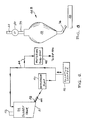
- FIG. 6 is a schematic representation of a slurry tank 34 and its associated circulation subsystem 35 which is utilized by the system 20.
- the tank may be of any suitable size or construction, but it is preferably fabricated as a plastic or fiberglass lined or coated stainless steel container and formed with a jacket 36 for cooling water or other suitable fluid to maintain the slurry at a controlled temperature.
- a typical size of the slurry tank which has beers utilized has a capacity of approximately 48 gallons of the slurry.
- the tank is preferably formed with a bottom 37 having a moderately angled slope, 5°, for example, in the direction of an outlet 38.
- the slope on the tank bottom 36 is intended to direct the solids in the slurry, if they are not fully dispersed, toward that side of the tank bottom which is nearest the outlet 38. This insures that a slurry rich in solids is brought to a recirculating diaphragm pump 40 which serves to cause flow of the slurry throughout the subsystem and, eventually, to the dip pan 30.
- a diaphragm pump 40 which performs adequately in the subsystem is a Sandpiper unit, model number SB1-A Type SN-1-A.
- the slurry tank 34 may be provided with an agitator 42 as further insurance in maintaining the uniform suspension of the solids within the slurry.
- Piping 44 for the subsystem can be of any suitable non-wetting material such as polyvinyl chloride (PVC) plastic pipe.
- PVC polyvinyl chloride
- pipe which has been found to be suitable is sold under the trademark "TYGON” and is distributed by Fisher Scientific Corporation.
- the non-wetting feature of the pipe assures that the system will not become clogged with resultant loss of costly slurry material.
- a pulsation damper 46 operates in a conventional manner in the subsystem to accommodate surges and provide uniform pressure throughout and thereby assure a constant rate of feed of slurry for the coating operation.
- An example of a damper which has satisfactory characteristics for the subsystem is one marketed under the trademark "Sandpiper", model TA-1-N-1-A, manufactured by Allen Pump Company of Cleveland, Ohio.
- the slurry metering subsystem which is supplied by the slurry tank 34 and its associated circulation subsystem is indicated generally at 48 in Figure 6. It serves to assure that proper control is maintained over the amount of slurry placed in the dip pan 30.
- a suitable metering subsystem is illustrated in Figure 7 and referred to by reference numeral 48A.
- the subsystem 48A includes an inverted bottle or bladder 50 which is suitably suspended from one end of a balance arm 52. Specifically, a screw 54 of nylon or other suitable material is threadedly engaged with the center of the bladder's top 56.
- a head of the screw 54 is slidably but snugly received in a suitable recess 58 provided in the underside of the balance arm and near its end.
- the screw 54 may be replaced by some other suitable fastener having a shank portion in some fashion engaged with the bladder.
- the bladder may even be molded to provide a similarly shaped but integral hanging device.
- the balance arm is notched in a central region of its underside, as at 60, to receive a hardened knife end 62 which is fixed on the structural framework 64 for the system 20.
- the bladder 50 is mounted from a location which is in line with its center of gravity and in a fashion which readily permits its insertion and removal, a distinct benefit for purposes of cleaning and replacement.
- a counterweight 66 is threadedly received on a stud 68 and serves to substantially balance the balance arm assembly about the knife edge 62 so as to initially null a load cell 70 whose operative finger 71 is sensitive to movement of the balance arm.
- the load cell 70 may have a digital readout (not shown), one example being that marketed under the trademark "Sensotec", Model 450D, Hi/Low Option, manufactured by Sensotec Corporation of Columbus, Ohio.
- a vibration dampener pad 72 preferably composed of a high density rubber or other suitable resilient material is applied to the balance arm so as to cushion the interface between the balance arm and the finder 71.
- the distance along the balance arm between the knife edge is 62 and the recess 58 from which the bladder 50 is suspended is preferably much greater than the distance between the knife edge and the point of contact of the finger 71 with the pad 72. This serves to provide a mechanical amplification of the weight of the slurry to minimize the contribution of electrical noise created by the load cell 70.
- the subsystem 48A also includes an intake line 73 which extends from the piping 44 in the circulation subsystem and loosely through a hole in the top 56 of the bladder 50.
- An isolation valve 73A positioned in the intake line 73 can be operated as needed to allow work to be performed on the subsystem 48A.
- an outlet line 74 is connected to, and extends from the bottom of the bladder 50 and serves to direct flow of the slurry by way of gravity feed to the dip pan 30 via a surge accumulator 74A.
- the lines 73 and 74 are preferably composed of rubber tubing or other suitable flexible conduit material.
- a first normally closed feed valve 75 which is suitably mounted on the framework 64, and which may be a pinch valve operated by compressed air from an air line 75A as illustrated in Figure 7 or any other suitable type of valve, operates on the line 73 to regulate flow of slurry into the bladder 50.
- a second normally closed feed valve 77 is mounted on a bracket 76 which is bolted or otherwise suitably attached to the balance arm adjacent its first end and extends downwardly therefrom.
- the valve 77 may be a pinch valve operated by compressed air from an air line 77A.
- the valve 77 serves to regulate the flow of slurry in the line 74 out of the bladder 50 and toward the dip pan 30.
- the intake line 73 Since the upper feed valve 75 is fixed to the framework 64, the intake line 73 must have sufficient length and extend a sufficient distance into the bladder 50 to accommodate movement of the bladder as the balance arm 52 swings on the knife edge 62. Unlike the intake line 73, the outlet line 74 moves in a unitary fashion with the bladder 50 and the lower feed valve 77. The outlet line 74 discharges the slurry into the surge accumulator 74A positioned between the bladder and the dip pan 30. The surge accumulator 77A enables the bladder 50 to be refilled while flow of the slurry continues into the dip pan.
- a constant head of approximately 2 feet of the slurry is preferably maintained on the upper or first feed valve 75.
- the load cell 70 is nulled by reason of the counterweight 66.
- a digital signal from a computer 78 ( Figure 15) directs the upper feed valve 75 to open to start the operation of filling the bladder 50.
- the finger 71 of the load cell 70 is moved upwardly ( Figure 7) in accordance with counterclockwise movement of the balance arm 52 and causes a signal to be transmitted to the computer 78 to operate the feed valve 75 to close and thereby terminate the filling procedure.
- the feed valve 77 is operated, upon command, for that purpose.
- the surge accumulator 74A enables the bladder 50 to be refilled while flow of the slurry continues into the dip pan. It will also be appreciated that the construction just described provides a weighing system which has a minimum of drag as it moves and therefore assures a high degree of accuracy. The construction also assures a rapid rate of response due to integration of digital (computer 78) and analog (load cell 70) devices. That is, the upper feed valve 75 is closed by signal from the load cell 70, then held closed by the computer 78 until the computer commands it to be again opened. Thus, scan time errors inherent in a digital system are eliminated by analog monitoring.
- a metering pump 80 is employed. It may be, for example, a pump such as model number NP - 31 manufactured and marketed by Bran and Lubbe of Wheeling, Illinois.
- the bladder 50 may be the same as previously described with respect to subsystem 48A.
- a head of slurry is provided by piping 44 to the inlet of the metering pump 80.
- the outlet of the pump connect by way of an intake line 73 into the bladder 50, the line 73 being of a type similar to that used in the embodiment of Figure 7.
- the outlet line 74 also generally as previously described, suitably connects the bladder 50 with the dip pan 30.
- the bladder may be utilized to avoid splashing since the metering pump, by its nature, delivers slurry in spurts. However, it should be understood that it is not necessary to utilize the bladder 50 in the system in which event the metering pump would provide flow of the slurry directly into the dip pan.
- the particular type of metering pump referred to above is preferably provided with a mechanical control to manually determine, in a known fashion, the length of stroke of the pump. By so controlling the stroke, the amount of charge placed into the dip pan 30 can be controlled as previously noted.
- the system illustrated in Figure 8 thus is based on volume control of the charge in contrast to the weight control utilized in the embodiment of Figure 7.
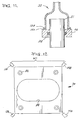
- the dip pan may be fabricated in any appropriate fashion and out of any suitable material.
- One such suitable material which has been employed is a plastic material manufactured by General Electric Company and sold under the trademark "Delrin", the generic name being "acetal”.
- the dip pan comprises a main body 82 in which is form a cavity 84 for receiving an end of the substrate. Also a plurality of suitable holes 86 are formed for releasably mounting it on a base 87 which, in turn, is fixed on the structural framework 64 of the system 20. In this manner, one main body 82 can be substituted for another according to the size of the cavity 84 in order to accommodate various sizes and contours of substrates.
- the dip pan 30 be fabricated of a non-wettable material, of which Delrin is an example. As with the piping 44, use of such material serves to avoid adherence of the costly slurry material after the draw up operation has been completed.
- Delrin has been mentioned as one suitable material, in actuality, any relatively non-wettable material with good dimensional stability can be used. Other such materials might be from the families of polystyrene and polypropylene.
- a non-wettable material is preferred, if a material chosen is slightly wetting, the first charge of slurry will serve to competely wet the cavity 84 and, once wetted, the entire amount of subsequent charges of slurry into the dip pan will be received on the substrate.
- the cavity 84 of the dip pan is preferably of a similar shape for convenience as well as for conservation of the slurry.
- the cavity 84 of the dip pan 30 is illustrated as having a clearance around the outer periphery of the substrate such that the substrate can be easily received within the cavity. Nevertheless, the position of the substrate is not critical and the process can be properly performed even if the substrate is closer to one side of the cavity than to the other. In practice, however, it has been found desirable to hold the end of the substrate 21 at a nominal distance of 0.040 inches (approx. 1.0 mm) above the bottom of the cavity 84 (see Figure 11).
- the gap between the end of the substrate and the bottom of a cavity in the dip pan has a tolerance of plus or minus 0.010 inches (approx. 0.25 mm) which is to say that the range of a preferred distance of the end of the substrate above the bottom of dip pan is between 0.030 inches (approx. 0.75 mm) and 0.050 inches (approx. 1.25 mm). As long as this gap tolerance is maintained, the end of the substrate need not be parallel with the bottom of the cavity of the pan.
- the periphery of the substance immersed in the slurry it is preferred to have the periphery of the substance immersed in the slurry to a depth of approximately 0.25 inch (approx. 6.4 mm). However, it is only necessary to have some slight amount of the periphery of the substrate covered by the slurry at the beginning of the draw up process.
- the process would not work because air around the lower end of the substrate rather than the slurry would be drawn up into the substrate.
- the high vacuum will assure that the slurry will continue to be drawn up into the substrate until no slurry remains in the cavity 84.
- a slurry inlet passageway 88 is formed in the main body 82 to receive an end of the outlet line 74 which communicates through a connecting aperture 90 with cavity 84.
- the passageway 88 and its associated connecting aperture 90 are illustrated as being angled approximately 15° with respect to the bottom of the cavity 84. However, the magnitude of this angle is not a critical value but need only be sufficiently large to assure the flow of slurry into the bottom of the cavity.
- the aperture 90 is flared so as to prevent splashing of the slurry as it flops into the cavity 84.
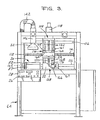
- FIG 14 illustrates in detail a rotary index arm 92 and the substrate clamp 24 rotatably mounted at an end of the arm 92.
- the clamp 24 is generally disc-shaped and is formed with a centrally located opening 96 which extends totally through the clamp from its first, now bottom, side 98 through to its second, now top side 100.
- the substrate is shown in phantom extending through the opening 96 and being held by the clamp over the dip pan 30.
- the clamp 24 holds the substrate by means of an inflatable gasket 102 which is suitably attached thereto within the opening 96 and attached to the clamp 24 for movement between a deflated condition withdrawn from the substrate at an inflated state engaging and holding the substrate midway its ends.
- a pressurized air line 104 is suitably connected to a source of high pressure air and, by means of a fitting 106, serves to introduce pressurized air through the body of the clamp 24 into the gasket 102.
- air is fed to the inflatable gasket through the air line 104 to inflate it and securely hold the substrate while it is being processed.
- the air is released from the gasket and its is deflated. An operator then merely slips the coated substrate out of the clamp and replaces it with a new substrate to be coated.
- the substrate clamp 24 is mounted on a pair of carriages 108 and 110 for movement, respectively, along the horizontal or X axis and along the vertical or Z axis.
- a servo motor 112 appropriately rotates a lead screw 114 to drive the carriage 110 backwards and forwards along the horizontal axis.
- Cooperating with the lead screw 114 are a pair of Thompson rods 116 which are spaces apart and parallel to the lead screw 114 and attached at their ends to the structural framework 64.
- the Thompson rods 116 are slidingly received on the carriage 108 to maintain its orientation relative to the framework as it is moved to and fro.
- a servo motor 118 operates a lead screw 120 which is threadedly engaged with the carriage 110 to move it up and down.
- Thompson rods 122 are mounted at their ends to the horizontal carriage 108 and are parallel to the lead screw 120 and slidingly received on the vertical carriage 110 to assure its orientation as it moves upwardly and downwardly.
- the horizontal carriage 108 moves the clamp 24 from the region of the shelf 22 over to the region of the dip pan 30 and back again.
- the vertical carriage 110 operates to move the clamp up and down both above the shelf 22 and above the dip pan.
- the clamp 24 is rotatably mounted in a suitable manner on the rotary index arm 92.
- the index arm 92 is, in turn, integral with the vertical carriage 110.
- a cylindrical extension 124 of the clamp 24, that portion of the clamp which is rotatably mounted on the index arm 92, has a segment gear 126 fixed at its end distant from the region of the opening 96 in the clamp 24.
- a rack 128 which is slidably mounted on the index arm 92 engages the gear 126 and is operable by a pneumatic actuator 130 to move upwardly and downwardly, and by so doing, to rotate the clamp 24 so as to reverse the positions of the bottom side 98 and top side 100.
- a lug 132 is fixed to the outer wall of the cylindrical extension 124 and extends radially outwardly therefrom and serves as part of a mechanism for stopping rotation of the clamp 24 and holding it fixed at the positions desired.
- the lug 132 is selectably held in engagement with a stop member 132 which is rigidly mounted on the index arm 92.
- the clamp 24 lies in a substantially horizontal plan with the first side 98 being a bottom side and the second side 100 being a top side.
- the actuator 130 can be operated to rotate the extension 124, and with it the lug 132, until the lug engages another stop member 136 also fixed to the index arm 92 by at a diametrically opposed location relative to the extension 124.
- the lug 132 is illustrated in dotted lines in Figure 14.
- the clamp 24 will have been rotated to a position such that the first side 98 becomes the top side, and the second side 100 becomes the bottom side.
- operation of the gear 126 and rack 128 causing the lug 132 to first engage one stop member 134 and then the other stop member 136 serves to rotate the extension 124 through an arc of 180°.
- a substrate 21 is supported by the clamp 24, in one position of the clamp, one end of the substrate is oriented for reception within the cavity 84; and when the clamp is rotated 180° and held as just described, the opposite end of the substrate is then oriented for reception within the cavity.
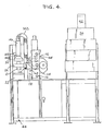
- the vacuum cone 32 serves to engage the end of the substrate 21 and by applying a vacuum draws the slurry up into the substrate from the dip pan.
- Reference now to Figure 11 will aid in further understanding the construction of the vacuum cone. It is seen that a lower rim 138 of the vacuum cone 32 suitably mounts a seal gasket 140 which sealingly engages a side of the clamp 24 in such a fashion as to essentially prevent the loss of vacuum when the cone and clamp are engaged. From Figure 11 it is seen that when a substrate is placed into the clamp 24, it is substantially centered along its longitudinal axis. It is also noteworthy that while the system can utilize different sizes of clamps 24 and dip pans with different sizes of cavities 84, all to accommodate different sizes of substrates, the vacuum cone 32 is so configured by reason of its bell shape to generally accommodate all sizes of substrates.
- the vacuum cone 32 is connected via a line 142 to a source of vacuum.
- a preferred arrangement for the source of vacuum is a vacuum pump 144 driven by a variable speed motor. At a low motor speed, low vacuum is generated in the range of 1 - 1/2 to 2 inches (approx. 38 to 50 mm) of water at 0 cfm; and at a high motor speed, high vacuum is generated in the range of 6 to 7 inches (approx. 150 to 175 mm) of water at 200 cfm.
- the vacuum cone 32 is positioned above the dip pan 30, appropriately supported on the structural framework 64, and accurately aligned with the cavity 84.
- the vacuum cone can be moved along guides 146A between a raised or inactive position and a lowered or active position for engagement with the upper end of the substrate 21. Its raised position is defined when a cam 145A which is integral with and protrudes from the vacuum cone 32 strikes a limit switch 145 mounted on the exterior of the air cylinder 146 ( Figure 4). Operation of the switch 145 deactivates the air cylinder 146 while the computer 78 serves to deactivate the air cylinder when the vacuum cone reaches its lowered position engaging the substrate.
- the downward movement of the vacuum cone is effected by the air cylinder 146 in a coordinated fashion with movement of the clamp 24 as it carries a substrate toward the dip pan. That is, the vacuum cone 32 is moved downwardly simultaneously with the substrate at substantially the same time, or slightly before, that the substrate enters the slurry in the dip pan.
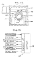
- FIG 13 generally illustrates an infrared sensor arrangement for controlling the height of the substrate 21 as it is placed into the dip pan with its lower end immersed in the slurry.
- the sensor arrangement incorporates a pair of sensor systems 147 each acting diagonally across the pan 30 and therefore across the path of movement of the substrate.
- Each sensor system contains a signal emitting source 148 and an associated detector 150, either a detector or a source being located in each corner of the pan.
- the sensor systems are commercially available units, one example being that sold under the trademark "Infra-Red Thru-Beam Switch" and manufactured by Balluff, Inc. of Florence, Kentucky.
- the purpose of the sensor systems is to determine when the lower end of the substrate approaches the pan and the charge held therein. Another purpose of the sensors and the reason for having two pairs of them, is to determine whether or not the substrate held in the clamp 24 is in a skewed position such that the end of the substrate would not properly enter the cavity 84. If such a situation were detected, the coating operation with respect to that substrate would be aborted and that particular substrate would be returned to the shelf 22 for repositioning by the operator. As the substrate approaches the dip pan upon downward movement of the clamp on the vertical carriage 110, its lower end activates the sensor system 147.
- the computer 78 ( Figure 15) takes over control of the further movement of the clamp to assure that the end of the substrate is held at the proper distance from the bottom of the dip pan and to regulate the point in which the high vacuum is placed on the substrate for the draw up operation.
- one sensor system 147 is adequate to determine whether a substrate is present and moving toward the dip pan. That is, as the substrate descends, it interrupts a signal emitted from the source 148 so that it is not received by the associated detector 150.
- two cooperating sensor systems are necessary to determine whether the substrate is properly oriented. Specifically, the two systems are so positioned ( Figure 12) such that the signals emitted and received by each detector are transverse to one another as well as to the path of travel of the substrate. In this manner, if the signals from both sources 148 to their associated detectors 150 are interrupted simultaneously, the computer 78 would be so informed and that would indicate that the substrate is properly oriented.
- the computer would understand that to mean that the substrate is not properly oriented for reception in the cavity 84. In that event, the computer can initiate appropriate alarms, perhaps audible, perhaps visual such as a light on the control panel 28, and cause operation of the system 20 to cease until the problem is corrected.
- the two sensor system operates in a similar fashion in event a sources 148 or detector 150 is accidentally splashed and coated with slurry thereby preventing it from functioning.
- the control subsystem for the system 20 generally comprises the start button 26 on the control panel 28 suitably mounted to the front of the framework 64, the computer 78 (Figure 15), the sensor systems 147 ( Figure 12), and numerous limit switches including 145 and others to be presented in the course of describing the operation of the system 20, below.
- One example of the computer 78 may be Model 2/15 sold under the trademark "Mini-PLC” by Allen-Bradley Company of Highland Heights, Ohio, which in fact, acts as the central processing unit (CPU) or brain of the system 20.
- the computer 78 receives information from the limit switches, sensor systems 14, and load cell 70 regarding the various stages of operation of the system and provides suitable instructions via an I/O interface 158 for operation for each of the subsystems in a proper, sequential manner.
- the operator manually loads the substrate to be coated into the substrate clamp 24 by placing its lower-most end on the shelf 22.
- the operator then pushes the start button 26 which simultaneously causes a number of operations to take place.
- a low vacuum is initially applied via line 142 to the vacuum cone 32.
- the slurry metering subsystem 48 meters a charge of slurry into the dip pan 30.
- the pneumatic actuator 130 is energized such that lug 132 is held firmly against stop member 134 thereby maintaining and firmly holding the substrate in its original orientation.
- pressurized air is introduced via the air line 104 to inflate the gasket 102 by which the clamp 24 firmly holds and supports the substrate.
- the vertical carriage 110 is driven upwardly on the vertical lead screw 120 about 0.25 inches (6.4 mm) off the top of the shelf 22 to raise the bottom of the substrate sufficiently to provide clearance for its subsequent horizontal movement.
- a limit switch 160 mounted on the carriage 110 engages a cam 161 mounted on the carriage 108 ( Figure 3)
- the horizontal lead screw 114 begins rotation to drive the horizontal carriage 108 horizontally to position it in alignment with the cavity 84 in the dip pan 30.
- a limit switch 162 suitably mounted on the framework 64 ( Figure 3) is provided to position the substrate over the dip pan as it moves from its position over the shelf 22 to its position over the dip pan.
- the limit switch 162 is aligned with the horizontal carriage 108 such that the outer surface of the carriage engages the switch at the point of extreme movement for the carriage. Actuation of the limit switch 162 not only serves to terminate rotation of horizontal lead screw 114, but also to initiate rotation, once again, of the vertical lead screw 120 to move the vertical carriage 110 downwardly and with it, the clamp 24 supporting the substrate. Actuation of the limit switch 162 also initiates downward movement of the vacuum cone 32.
- the motor is activated by the computer 78 to generate the low vacuum as previously described when the vacuum cone begins to descend.
- Movement of the vacuum cone and of the clamp supported substrate is coordinated such that when the lower end of the substrate enters the slurry in the dip pan, or slightly before, the vacuum cone sealingly envelopes the upper end of the substrate. This aids in evacuating the substrate before it reaches its terminal position.
- the further movement of the lower end of the substrate into the dip pan then becomes controlled by the computer 78 until brought to a position approximately 0.040 inches (approx. 1.0 mm) above the bottom of the cavity 84.
- the vacuum cone descends until it sealingly envelopes the upper end of the substrate.
- the low vacuum being applied to the vacuum cone 32 serves to draw the slurry up into the interior of the substrate. This process of drawing the slurry up into the interior of the substrate is sometimes referred to as "loading" of the slurry.
- the computer operates the motor to develop the high vacuum, as previously described, which is applied via the line 142 to the vacuum cone 32. It takes approximately one second for high vacuum to be developed and such operation continues for a sufficiently long duration to enable the slurry in the dip pan to be drawn completely up into the lower portion of the substrate.
- the purpose of loading the slurry using two levels of vacuum is to avoid "spiking" of the coating slurry in the interior passageways of the substrate. Spiking is a phenomenon which occurs when the initial vacuum applied is too high and the slurry is therefore not drawn uniformly up into the cells of the substrate.
- the vertical lead screw 120 is again operated to drive the vertical carriage 110 and the clamp 24 upwardly and away from the dip pan. Even as this occurs, however, the vacuum cone 32 continues to be engaged with the clamp and connected to the high vacuum source. In this manner, air is drawn through the substrate to thereby drawn the slurry which has just been deposited at the lower end of the substrate deeper into the interior thereof and to coat evenly all the cells of the substrate.
- This continued application of high vacuum to the substrate is referred to as a "spreading" or “distribution” step and continues for approximately 3 to 4 seconds, substantially the duration required for the clamp to reach a dwell position.
- the clamp is raised for this operation in order to permit rotation of the substrate as will be described below and to eliminate any obstruction that the dip pan or other equipment in its vicinity would create preventing the flow of air into the lowermost end of the substrate.
- a second charge of slurry destined to be loaded through the opposite end of the substrate, is dispensed and received within the cavity 84 of the dip pan 30.
- both ends of the substrate are clear, respectively, of the dip pan 30 and of the vacuum cone 32 enabling the next step to be performed, that is, the 180° rotation of the substrate.
- the ends of the substrate are reoriented, the previous lower end now being an upper end and the previous upper end now being a lower end.
- the clamp 24 and its supported substrate are moved and held in the new position by the actuator 130, the lug 132 now engaging the stop member 136.
- the clamp continues to be held in that position by the actuator 130 until the computer 78 instructs it to return to its original position at a later time in the process.
- the computer 78 again takes over operation of the system to move the substrate downwardly toward the cavity 84.
- the procedure previously described with respect to loading of the first end of the substrate is now repeated with second end.
- the clamp 24 together with the vacuum cone 32 is once again raised to its uppermost position over the dip pan 30, its upward movement again terminated by reason of the limit switch 164.
- the vacuum cone 32 is disengaged from the clamp 24 and returns to its home position as defined by the limit switch 145.
- the limit switch 164 also serves to cause operation of the pneumatic actuator 130 to again rotate the clamp 24, returning the substrate to its original position. Thereupon, the horizontal lead screw 114 is again operated to translate the clamp from a position over the dip pan to a position over the shelf 22. Horizontal movement of the clamp 24 is terminated when a limit switch 166 suitably mounted on the carriage 108 engages a cam 167 fixed to the framework 64. See Figures 3 and 4. This, in turn, activates the vertical lead screw 120 to lower the clamp 24 and, with it, the substrate such that its lower end is returned to the shelf with its original orientation.
- a limit switch 168 mounted on the carriage 110 engages a cam 170 fixed on the carriage 110 which serves to deenergize the system 20 and all of its subsystems.
- pressure to the gasket 102 is removed enabling the gasket 102 to deflate and be withdrawn from engagement with the substrate.
- the operator can then remove the coated substrate from the clamp and put an uncoated substrate back into the clamp for another cycle of the loading process.
- the entire procedure as described for coating of a single substrate takes approximately 30 to 40 seconds of time.
Landscapes
- Chemical & Material Sciences (AREA)
- Engineering & Computer Science (AREA)
- Materials Engineering (AREA)
- Organic Chemistry (AREA)
- Chemical Kinetics & Catalysis (AREA)
- Catalysts (AREA)
- Coating Apparatus (AREA)
- Elimination Of Static Electricity (AREA)
- Preparation Of Compounds By Using Micro-Organisms (AREA)
- Application Of Or Painting With Fluid Materials (AREA)
Claims (45)
- Procédé pour appliquer une quantité prédéterminée d'un catalyseur sur les surfaces intérieures d'un substrat creux, incluant les étapes consistant à:a) introduire une quantité prédéterminée d'une boue d'un catalyseur dans la cavité d'une cuvette à immersion comportant un fond;b) abaisser un substrat creux possédant des première et seconde extrémités ouvertes et des surfaces intérieures devant être recouvertes, de manière qu'une première extrémité soit introduite dans la cavité de la cuvette à immersion et complètement immergée dans la boue;c) maintenir le substrat à une hauteur telle que sa première extrémité est située à une distance prédéterminée au-dessus du fond de la cavité située dans la cuvette à immersion; etd) appliquer une dépression à partir d'une source à la seconde extrémité du substrat de manière à entraîner vers le haut l'ensemble de la boue contenue dans la cuvette à immersion, pour la faire pénétrer dans le substrat afin qu'elle recouvre les surfaces extérieures de ce dernier;
caractérisé en ce que ledit procédé comprend en outre l'étape consistant à:e) continuer à appliquer la dépression pendant un intervalle de temps prédéterminé à la seconde extrémité du substrat une fois que toute la boue a été entraînée hors de la cuvette à immersion et a pénétré dans le substrat, de manière à faire sécher le recouvrement formé sur le substrat. - Procédé selon la revendication 1 comprenant les étapes supplémentaires consistant à:f) soulever le substrat à une hauteur, où on l'arrête, de manière que ses extrémités soient dégagées respectivement de la cuvette à immersion et de la source de dépression;g) faire tourner le substrat de manière à inverser les positions relatives de ses première et seconde extrémités;h) introduire à nouveau une quantité prédéterminée de boue dans la cavité de la cuvette à immersion;i) abaisser le substrat de manière que la seconde extrémité pénètre dans la cavité de la cuvette à immersion et soit immergée dans la boue;j) maintenir le substrat à une hauteur telle que sa première extrémité est située à une distance prédéterminée au-dessus du fond de la cavité située dans la cuvette à immersion;k) appliquer une dépression à partir de la source à la première extrémité du substrat de manière à entraîner vers le haut l'ensemble de la boue située dans la cuvette à immersion, pour qu'elle pénètre dans le substrat de manière à recouvrir la surface intérieure de ce dernier; etl) continuer à appliquer la dépression pendant un intervalle de temps prédéterminé à la seconde extrémité du substrat une fois que l'ensemble de la boue a été entraîné hors de la cuvette à immersion et a pénétré dans le substrat, de manière à faire sécher le recouvrement formé sur le substrat.
- Procédé selon la revendication 2, incluant les étapes consistant à:m) retirer la source de dépression de la seconde extrémité du substrat;n) soulever à nouveau le substrat jusqu'à une hauteur, à laquelle il est arrêté, de manière que ses extrémités soient dégagées respectivement de la cuvette à immersion et de la source de dépression; eto) faire tourner le substrat de manière à amener ses première et seconde extrémités dans leur orientation relative initiale.
- Procédé selon la revendication 1, dans lequel les étapes d) et e) comprennent:a) une application d'une faible dépression initiale et ultérieurement d'une dépression intense à partir d'une source à la seconde extrémité du substrat de manière à entraîner vers le haut l'ensemble de la boue contenue dans la cuvette à immersion pour qu'elle pénètre dans le substrat de manière à recouvrir les surfaces intérieures de ce dernier; etb) une poursuite de l'application de la dépression intense pendant un laps de temps prédéterminé à la seconde extrémité du substrat une fois que toute la boue a été entraînée hors de la cuvette à immersion et a pénétré dans le substrat, de manière à faire sécher le recouvrement formé sur le substrat.
- Procédé pour appliquer une quantité prédéterminée d'un catalyseur sur les surfaces intérieures d'un substrat creux, comprenant les étapes consistant à:a) introduire une première quantité prédéterminée d'une boue d'un catalyseur dans la cavité d'une cuvette à immersion;b) abaisser un substrat creux possédant des première et seconde extrémités ouvertes et des surfaces intérieures devant être recouvertes, de manière qu'une première extrémité pénètre dans la cavité de la cuvette à immersion et soit totalement immergée dans la boue;c) appliquer une dépression à la seconde extrémité du substrat pour entraîner vers le haut l'ensemble de la boue contenue dans la cuvette à immersion, pour la faire pénétrer dans le substrat à travers la première extrémité, afin qu'elle recouvre les surfaces intérieures de ce dernier;d) retirer la source de dépression de la seconde extrémité du substrat; ete) soulever le substrat jusqu'à une hauteur, à laquelle on l'arrête, de manière que ses extrémités soient respectivement dégagées de la cuvette a immersion et de la source de dépression;
caractérisé en ce que ledit procédé comprend en outre les étapes consistant à:f) faire tourner le substrat de manière à inverser les positions relatives de ses première et seconde extrémités;g) introduire une seconde quantité prédéterminée d'une boue dans la cavité de la cuvette a immersion;h) abaisser le substrat de manière que sa seconde extrémité pénètre dans la cavité de la cuvette à immersion et soit complètement immergée dans la boue; eti) appliquer une dépression à la première extrémité du substrat de manière à entraîner vers le haut l'ensemble de la boue contenue dans la cuvette à immersion pour la faire pénétrer dans le substrat à travers la seconde extrémité, de manière qu'elle recouvre les surfaces intérieures de ce dernier. - Procédé selon une revendication précédente quelconque dans lequel l'étape b) comprend:
un transfert, à partir d'une position initiale, d'un substrat creux possédant des première et seconde extrémités ouvertes et des surfaces intérieures devant être recouvertes de telle sorte que la première extrémité s'avance vers la cavité de la cuvette à immersion apte à recevoir en elle la première extrémité de manière à en permettre l'immersion complète dans la boue du catalyseur;
une détection de la présence du substrat lorsque sa première extrémité franchit un plan situé au-dessus de la cavité et situé transversalement par rapport au trajet de déplacement du substrat;
un arrêt du déplacement du substrat lorsque sa première extrémité atteint une position opérationnelle, dans laquelle il est situé à une distance prédéterminée au-dessus du fond de la cavité et est totalement immergé dans la boue du catalyseur. - Procédé selon une revendication précédente quelconque dans lequel la quantité prédéterminée prévue à l'étape a) est un poids prédéterminé de la boue.
- Procédé selon la revendication 7 dans lequel l'étape a) comprend:a) une production d'un écoulement de la boue depuis un réservoir dans un moyen en forme de ballon;b) une pesée en continu des moyens en forme de ballon au fur et à mesure que la boue y pénètre;c) un arrêt d'écoulement de la boue dans le moyen en forme de ballon lorsque le poids de la boue dans ces derniers a atteint une valeur prédéterminée; etd) une libération, ensuite, de l'ensemble de la boue située dans le moyen en forme de ballon pour l'amener à pénétrer dans la cuvette à immersion en vue de réaliser le recouvrement des surfaces intérieures du substrat.
- Procédé selon l'une des revendications 1 à 6 dans lequel la quantité prédéterminée prévue à l'étape a) est un volume prédéterminé de la boue.
- Procédé selon la revendication 9 dans lequel l'étape a) comprend:
le fait d'amener la boue à s'écouler, à partir d'un réservoir, dans un moyen en forme de ballon;
un arrêt de l'écoulement de la boue dans le moyen en forme de ballon lorsque le volume de la boue dans ce dernier atteint une valeur prédéterminée; et
une libération ultérieure de l'ensemble de la boue située dans le moyen en forme de ballon pour l'amener à pénétrer dans la cuvette à immersion, en vue de recouvrir les surfaces intérieures du substrat. - Procédé selon une revendication précédente quelconque incluant les étapes consistant à:
placer un substrat devant être recouvert sur une plate-forme, dans l'espace enserré par une pince pouvant être actionnée de façon sélective de manière à contacter fermement et à supporter le substrat;
faire fonctionner la pince pour qu'elle contacte fermement et supporte le substrat;
soulever, au-dessus de la plate-forme, la pince et le substrat soutenu pour l'amener dans une première position d'arrêt;
transférer la pince et le substrat soutenu jusque dans une seconde position d'arrêt, dans une position alignée verticalement avec et entre un cône à dépression et une cuvette à immersion comportant une cavité servant à recevoir la boue du catalyseur;
introduire une quantité prédéterminée de la boue du catalyseur dans la cavité de la cuvette à immersion;
abaisser la pince de manière qu'une première extrémité du substrat soutenu pénètre dans la cavité de la cuvette à immersion;
détecter la présence du substrat lorsque sa première extrémité franchit un plan situé au-dessus de la cavité et disposé transversalement par rapport à la trajectoire de déplacement du substrat;
arrêter le déplacement de la pince lorsque la première extrémité du substrat atteint une position opérationnelle, à une distance prédéterminée au-dessus du fond de la cavité, et est immergée dans la boue du catalyseur;
en même temps que s'effectue l'étape d'abaissement de la pince, abaisser le cône à dépression pour l'amener en contact étanche avec une seconde extrémité du substrat située à l'opposé de la première extrémité de ce dernier, lorsque cette première extrémité est située dans la position opérationnelle;
appliquer une dépression au cône à dépression pour entraîner complètement la boue de catalyseur située dans la cavité dans la première extrémité du substrat pour recouvrir les surfaces intérieures de ce dernier les plus proches de la première extrémité;
continuer à appliquer une dépression au cône pendant une période prédéterminée tout en abaissant la pince, le substrat et le cône à dépression sous la forme d'une unité jusque dans la seconde position d'arrêt, dans laquelle la première extrémité est dégagée de la cuvette à immersion, ce qui permet le séchage du recouvrement de la boue du catalyseur située sur les surfaces intérieures du substrat;
interrompre l'application de la dépression au cône à dépression;
retirer le cône à dépression dans une position rétractée écartée de la pince et du substrat;
faire tourner la pince autour d'un axe de manière à modifier les positions respectives des première et seconde extrémités du substrat;
introduire à nouveau une quantité prédéterminée de la boue du catalyseur dans la cavité de la cuvette à immersion;
abaisser la pince de manière que la seconde extrémité du substrat pénètre dans la cavité de la cuvette à immersion;
détecter la présence du substrat lorsque sa seconde extrémité franchit un plan situé au-dessous de la cavité et transversal par rapport au trajet de déplacement du substrat;
arrêter le déplacement de la pince lorsque la seconde extrémité du substrat atteint une position opérationnelle à une distance prédéterminée au-dessus du fond de la cavité et est totalement immergée dans la boue du catalyseur;
en même temps que s'effectue l'étape d'abaissement de la pince, abaisser à nouveau le cône à dépression pour l'amener en contact étanche avec la première extrémité du substrat lorsque la seconde extrémité se trouve dans la position opérationnelle;
appliquer une dépression au cône à dépression de manière à entraîner complètement la boue du catalyseur située dans la cavité pour l'amener dans la seconde extrémité du substrat afin de recouvrir les surfaces intérieures de ce dernier à proximité de sa seconde extrémité;
continuer, pendant une période de temps prédéterminée, à appliquer une dépression au cône à dépression tout en abaissant la pince, le substrat et le cône à dépression sous la forme d'une unité jusque dans la seconde position d'arrêt, de manière à faire sécher le recouvrement de la boue du catalyseur située sur les surfaces intérieures du substrat;
arrêter l'application de la dépression au cône à dépression;
retirer le cône à dépression dans une position rétractée distante de la pince et du substrat;
faire tourner à nouveau la pince autour d'un axe de manière à modifier les positions respectives des première et seconde extrémités du substrat;
transférer la pince et le substrat soutenu de manière à les ramener dans la première position d'arrêt;
abaisser la pince de manière que la première extrémité soit amenée à nouveau en appui sur la plate-forme; et
dégager la pince du substrat. - Appareil pour appliquer une quantité prédéterminée d'un catalyseur sur les surfaces intérieures d'un substrat creux, comprenant:
des moyens en forme de pince contactant fermement et supportant un substrat creux comportant des première et seconde extrémités opposées ouvertes;
une cuvette d'immersion possédant une cavité possédant un fond pour retenir en elle une quantité prédéterminée d'une boue d'un catalyseur et apte à recevoir en elle une extrémité du substrat;
des premiers moyens d'entraînement servant à déplacer lesdits moyens en forme de pince selon un mouvement ascendant et un mouvement descendant le long d'un trajet qui d'une manière générale est vertical et est aligné avec la cavité de ladite cuvette à immersion; et
des moyens de commande servant à commander le déplacement desdits premiers moyens d'entraînement le long dudit trajet vertical, caractérisé en ce que lesdits moyens de commande comprennent des moyens de détection servant à détecter la présence d'une première extrémité du substrat lorsqu'elle se rapproche de ladite cuvette à immersion lorsque ladite pince et ledit substrat soutenu sont abaissés le long dudit trajet vertical, lesdits moyens de commande pouvant agir de manière à arrêter le déplacement descendant desdits premiers moyens d'entraînement lorsque la première extrémité du substrat atteint une position, dans laquelle elle est totalement immergée dans la boue et est située à une distance prédéterminée au-dessus du fond de ladite cuvette à immersion. - Appareil selon la revendication 12 comportant un cône à dépression et un conduit raccordant de façon opérationnelle ledit cône à dépression à une source de dépression, ledit cône à dépression possédant une extrémité ouverte pouvant être déplacée entre une position rétractée distante de la seconde extrémité du substrat et une position déployée permettant d'envelopper d'une manière étanche la seconde extrémité du substrat lorsque la première extrémité de ce dernier est immergée dans la boue.
- Appareil selon la revendication 13, dans lequel ledit cône à dépression peut être saisi par ladite pince de manière à envelopper de façon étanche la seconde extrémité du substrat et comporte des moyens d'étanchéité servant à rendre étanche d'une manière efficace l'interface entre ledit cône à dépression et ladite pince lorsque ces derniers sont en contact réciproque.
- Appareil selon la revendication 14, dans lequel ledit cône à dépression possède la forme d'une cloche et se termine par un rebord, lesdits moyens d'étanchéité étant constitués par une garniture d'étanchéité continue montée sur ledit rebord et pouvant être contactée par ladite pince, ce qui permet une adaptation à une gamme étendue de tailles de substrats.
- Appareil selon la revendication 13 comportant des seconds moyens d'entraînement pour déplacer ledit cône à dépression entre lesdites positions rétractée et déployée, lesdits moyens de commande agissant de manière à faire fonctionner lesdits premiers et seconds moyens d'entraînement de manière que ledit cône à dépression enveloppe d'une manière étanche la seconde extrémité du substrat, essentiellement au même moment où le substrat sur ladite pince pénètre dans la boue située dans la cuvette à immersion.
- Appareil selon la revendication 13, caractérisé en ce que ladite source de dépression peut fonctionner en alternance à un faible niveau de dépression et à un niveau élevé de dépression, et dans lequel lesdits moyens de commande agissent de manière à faire fonctionner initialement ladite source audit faible niveau lorsque ledit cône à dépression enveloppe tout d'abord de façon étanche ledit substrat, et audit niveau élevé une fois que ledit cône à dépression a enveloppé d'une manière étanche ledit substrat pendant un intervalle de temps prédéterminé.
- Appareil selon la revendication 17, dans lequel lesdits moyens de commande peuvent agir de manière à appliquer de façon sélective une dépression réduite audit cône à dépression lorsque ledit cône à dépression enveloppe initialement de façon étanche le substrat, puis de manière à appliquer une dépression élevée audit cône à dépression une fois que ledit cône à dépression a enveloppé de façon étanche le substrat pendant une période prédéterminée et de manière à empêcher l'application de ladite dépression élevée audit cône à dépression lorsque ce dernier est retiré du substrat.
- Appareil selon la revendication 17, dans lequel lesdits moyens de commande peuvent agir de manière à appliquer de façon sélective une forte dépression audit cône à dépression une fois que ledit cône à dépression a enveloppé de façon étanche le substrat pendant un intervalle de temps prédéterminé, et de manière à arrêter l'application de ladite dépression élevée audit cône à dépression lorsque ledit cône à dépression est retiré du substrat.
- Appareil selon la revendication 19, dans lequel lesdits moyens de commande peuvent agir de manière à déplacer jusque dans une position d'arrêt, sous la forme d'une unité, ladite pince et ledit cône à dépression, alors que ledit cône à dépression entoure encore de façon étanche la seconde extrémité du substrat de telle sorte que ce dernier est dégagé de ladite cuvette à immersion, et, après l'écoulement d'un autre intervalle de temps prédéterminé, peuvent actionner lesdits seconds moyens d'entraînement pour retirer ledit cône à dépression de la seconde extrémité du substrat et amener ledit cône à dépression dans la position rétractée.
- Appareil selon la revendication 20, dans lequel lesdits moyens de commande peuvent agir de manière à déplacer ladite pince jusqu'à une hauteur, dans laquelle elle est arrêtée, telle que les extrémités du substrat sont dégagées dudit cône à dépression et de ladite cuvette à immersion, dans ladite position rétractée, et qu'il est prévu des moyens pour faire tourner ladite pince de manière à inverser les positions relatives des première et seconde extrémités du substrat, lesdits moyens de commande pouvant agir de manière à faire tourner ladite pince lorsque cette dernière a atteint ladite hauteur, à laquelle elle est arrêtée.
- Appareil selon la revendication 17, dans lequel ladite source à dépression comprend une pompe à dépression pouvant être actionnée dans une gamme étendue de vitesses de manière à produire une gamme étendue de dépressions en fonction de la vitesse, et un moteur à vitesse variable servant à entraîner ladite pompe, ce qui a pour effet que l'actionnement dudit moteur à une faible vitesse amène ladite pompe à dépression à produire une faible dépression, et que l'actionnement dudit moteur à une vitesse élevée amène ladite pompe à produire une dépression importante.
- Appareil selon la revendication 12, lesdits moyens de commande comprenant des moyens de détection servant à détecter la présence et l'orientation du substrat par rapport à ladite cuvette à immersion lorsqu'une extrémité du substrat franchit, en descendant, un plan situé au-dessous de la cavité et transversal par rapport au trajet de déplacement du substrat, lesdits moyens de commande pouvant agir de manière à permettre un déplacement continu de ladite pince lorsque l'orientation du substrat est telle qu'il est certain que son extrémité pénètre de façon correcte à l'intérieur de la cavité de ladite cuvette à immersion, lesdits moyens de commande pouvant agir de manière à arrêter le fonctionnement desdits premiers moyens d'entraînement et de ce fait le déplacement descendant du substrat lorsque l'extrémité de ce dernier atteint une position opérationnelle située à une distance prédéterminée au-dessus du fond de la cavité et totalement immergée dans la boue.
- Appareil selon la revendication 23,dans lequel lesdits moyens de commande arrêtent l'actionnement desdits premiers moyens d'entraînement déplaçant ladite pince vers le bas en direction de ladite cuvette à immersion lorsque l'orientation du substrat est telle que le substrat n'est pas reçu de façon correcte à l'intérieur de la cavité de ladite cuvette à immersion en vue de son immersion dans la boue.
- Appareil selon la revendication 23, dans lequel lesdits moyens de détection incluent au moins une source d'émission de signaux et au moins un détecteur associé, séparé de ladite source et disposé de telle sorte que ledit trajet vertical est situé entre ladite source et ledit détecteur, le passage du substrat entre ladite source et ledit détecteur ayant pour effet d'interrompre le signal délivré par ladite source de manière à indiquer de ce fait la présence du substrat.
- Appareil selon la revendication 23, dans lequel lesdits moyens de détection comprennent des première et seconde sources d'émission de signaux et des premier et second détecteurs associés séparés desdites sources de telle sorte que les signaux émis et reçus par chacun desdits moyens de détection s'étendent transversalement les uns par rapport aux autres et par rapport audit trajet vertical, lesdits moyens de détection étant disposés de telle sorte que ledit trajet vertical est situé entre chacune desdites sources et desdits détecteurs, le passage d'un substrat ayant pour effet d'interrompre le signal délivré par chacune desdites sources simultanément pour indiquer de ce fait la présence du substrat et étant apte à interrompre le signal délivré par chacune desdites sources successivement pour indiquer de ce fait une orientation incorrecte du substrat.
- Appareil selon la revendication 24, comprenant:
une étagère distante de ladite cuvette à immersion et apte à recevoir, de manière à le supporter, un substrat; et
des troisièmes moyens d'entraînement pouvant être actionnés par lesdits moyens de commande afin de déplacer latéralement ladite pince entre une position alignée avec ladite étagère et une position alignée avec ladite cuvette à immersion;
lesdits moyens de commande amenant successivement lesdits premiers moyens d'entraînement à déplacer ladite pince vers le haut jusque dans une position d'arrêt au-dessus de ladite cuvette à immersion et à distance de cette dernière, puis amenant lesdits troisièmes moyens d'entraînement à déplacer ladite pince latéralement jusque dans ladite position alignée avec ladite étagère, puis amenant lesdits moyens d'entraînement à déplacer ladite pince vers le bas pour placer le substrat sur ladite étagère. - Appareil pour appliquer une quantité prédéterminée d'un catalyseur sur les surfaces intérieures d'un substrat creux comportant des extrémités opposées, comprenant:
une cuvette à immersion possédant une cavité munie d'un fond et de côtés pour retenir en elle une quantité prédéterminée d'une boue d'un catalyseur et apte à recevoir en elle une extrémité du substrat;
un réservoir servant à contenir la boue du catalyseur en un emplacement distant de ladite cuvette à immersion;
des moyens en forme de conduits s'étendant entre ledit réservoir et ladite cuvette à immersion de manière à diriger l'écoulement de la boue du catalyseur depuis ledit réservoir jusqu'à ladite cuvette à immersion; et
un moyen de délivrance pouvant agir de façon sélective pour amener l'écoulement de la boue du catalyseur depuis ledit réservoir jusqu'à ladite cuvette à immersion, caractérisé en ce que ledit moyen de délivrance comprend un ballon apte à recevoir en lui une charge de la boue de catalyseur en vue d'une introduction éventuelle dans ladite cuvette à immersion. - Appareil selon la revendication 28, comportant:
des moyens de commande servant à déclencher une pluralité de fonctions dudit appareil conformément à une séquence et un cadencement prédéterminés, et dans lequel lesdits moyens de délivrance comprennent:
une première soupape électromagnétique normalement fermée servant à commander l'écoulement de la boue dans ledit ballon, ladite première soupape électromagnétique pouvant être actionnée par lesdits moyens de commande de manière à venir dans la position ouverte pendant un intervalle de temps prédéterminé afin de permettre l'écoulement de la boue dans ledit ballon;
des moyens de mesure pour peser la quantité de boue située dans ledit ballon et comportant des moyens de transmission de signaux servant à produire et à émettre de façon continue, en direction desdits moyens de commande, un signal représentatif du poids de la boue de catalyseur située dans ledit ballon; et
une seconde soupape électromagnétique normalement fermée servant à commander l'écoulement de la boue sortant dudit ballon et pénétrant dans ladite cuvette à immersion, ladite seconde soupape électromagnétique répondant auxdits moyens de commande lorsque le poids de la boue située dans ledit ballon atteint un poids prédéterminé, pour venir dans la position ouverte afin de permettre l'écoulement de la boue depuis ledit ballon dans ladite cuvette à immersion. - Appareil selon la revendication 29, dans lequel lesdits moyens de mesure incluent une plate-forme pouvant être actionnée de manière à produire un signal représentatif d'une charge reçue en elle et dans lequel lesdits moyens de délivrance comprennent un boîtier servant à supporter ledit ballon, ladite plate-forme étant apte à supporter ledit boîtier.
- Appareil selon la revendication 28, dans lequel lesdits moyens de délivrance comprennent:
des moyens de commande servant à déclencher une pluralité de fonctions dudit appareil conformément à une séquence et un cadencement prédéterminés;
des moyens de support pour ledit ballon, comprenant un boîtier possédant un élément de base et une ouverture traversant le boîtier, une cellule de charge située dans ledit boîtier, des moyens élastiques supportant ladite cellule de charge de manière qu'elle ait un déplacement limité par rapport audit élément de base, une tige de liaison située essentiellement verticalement et s'étendant à travers l'ouverture et fixée à une extrémité à ladite cellule de charge et à son autre extrémité audit ballon, des moyens de support situés sur ledit élément de base à l'intérieur de l'ouverture permettant le déplacement axial de ladite tige de liaison par rapport audit élément de base;
ladite cellule de charge étant sensible au poids de la boue située dans ledit ballon et comprenant des moyens de transmission de signaux servant à produire et émettre de façon continue, en direction desdits moyens de commande, un signal représentatif du poids de la boue située dans ledit ballon; et
une première soupape électromagnétique normalement fermée servant à commander l'écoulement de la boue dans ledit ballon, ladite première soupape électromagnétique pouvant être actionnée par lesdits moyens de commande de manière à venir dans la position ouverte afin de permettre l'écoulement de la boue dans ledit ballon, et répondant auxdits moyens de commande de manière à venir dans la position fermée afin d'arrêter l'écoulement de la boue pénétrant dans ledit ballon lorsque la boue située à l'intérieur dudit ballon atteint un poids prédéterminé. - Appareil selon la revendication 28, dans lequel lesdits moyens de délivrance comprennent:
des moyens de commande servant à déclencher une pluralité de fonctions dudit appareil conformément à une séquence et un cadencement prédéterminés;
des moyens de support pour ledit ballon, comprenant une arête de couteau fixe dirigée vers le haut, un bras de balance allongé comportant des première et seconde extrémités et monté pivotant sur ladite arête de couteau entre lesdites extrémités, et des moyens d'engrènement réciproque situés au voisinage de ladite première extrémité et sur ledit ballon de manière à permettre le montage dudit ballon sur ces moyens;
des moyens formant contrepoids, sollicitant ladite seconde extrémité dudit bras de la balance pour compenser le poids à dudit ballon;
une cellule de charge pouvant engrener avec ladite seconde extrémité dudit bras de la balance pour détecter le poids de la boue lorsqu'elle est introduite dans ledit ballon et comprenant des moyens de signalisation servant à produire et à émettre, en direction desdits moyens de commande, un signal représentatif du poids de la boue située dans ledit ballon;
une première vanne d'alimentation normalement fermée servant à commander l'écoulement de la boue dans ledit ballon, ladite première vanne d'alimentation pouvant être actionnée par lesdits moyens de commande de manière à être amenée dans la position ouverte afin de permettre l'écoulement de la boue dans ledit ballon, et répondant auxdits moyens de commande de manière à venir dans la position fermée afin d'arrêter l'écoulement de la boue pénétrant dans ledit ballon lorsque la boue située à l'intérieur dudit ballon a atteint un poids prédéterminé détecté par ladite cellule de charge. - Appareil selon la revendication 32, dans lequel lesdits moyens formant contrepoids comprennent au moins un contrepoids fixé de façon détachable à ladite seconde extrémité.
- Appareil selon la revendication 32, dans lequel la distance linéaire entre un centre de gravité dudit ballon et ladite arête de couteau est nettement supérieure à la distance linéaire entre ladite arête de couteau et l'emplacement dans lequel ladite cellule de charge engrène avec ladite seconde extrémité dudit bras de la balance.
- Appareil selon la revendication 32, dans lequel ledit ballon comporte une extrémité supérieure et une canalisation d'admission pour la boue, raccordée à ladite extrémité supérieure, ladite première vanne d'alimentation pouvant agir de manière à commander l'écoulement de la boue depuis ledit réservoir dans ledit ballon par l'intermédiaire de la canalisation d'admission, et dans lequel ledit ballon comporte une extrémité inférieure et une canalisation de sortie fixée à ladite extrémité inférieure de manière à diriger l'écoulement de la boue en direction de ladite cuvette à immersion;
ledit appareil comprenant une seconde vanne d'alimentation normalement fermée placée dans ladite canalisation de sortie de manière à commander l'écoulement de la boue sortant dudit ballon, lors de l'arrivée dudit signal délivré par lesdits moyens de commande. - Appareil selon la revendication 32, dans lequel lesdits moyens d'engrènement réciproque comprennent un renfoncement défini situé au voisinage de ladite première extrémité et un organe de fixation comportant une partie élargie fixée sur ledit ballon et écartée de la surface de ce dernier, ladite partie élargie pouvant être reçue, selon une liaison d'engrènement, dans ledit renfoncement de manière à suspendre de ce fait ledit ballon audit bras de la balance.
- Appareil selon la revendication 36, dans lequel ledit organe de fixation est une vis engrenant par vissage avec ledit ballon, ladite vis comportant une tête logée selon une liaison d'engrènement à l'intérieur dudit renfoncement de manière à suspendre de ce fait ledit ballon audit bras de la balance.
- Appareil selon la revendication 36, dans lequel ledit ballon comporte une extrémité supérieure, sur laquelle ledit organe de fixation est monté, et une extrémité inférieure, et dans lequel lesdits moyens de support comprennent une console fixée audit bras de la balance et s'étendant vers le bas au voisinage de ladite première extrémité, et un anneau de support fixé à ladite console et distant de ladite première extrémité et apte à recevoir ladite extrémité inférieure, de manière à la supporter librement.
- Appareil selon la revendication 28, dans lequel ledit réservoir est une cuve comportant un fond et possédant une sortie ménagée dans son fond et raccordée auxdits moyens en forme de conduit, ledit fond étant incliné en direction de la sortie de manière à diriger l'écoulement de la boue en direction desdits moyens en forme de conduits.
- Appareil selon la revendication 28, dans lequel ladite cuvette à immersion, ledit réservoir et lesdits moyens en forme de conduits sont réalisés en un matériau essentiellement non mouillable.
- Appareil selon la revendication 28, dans lequel ledit réservoir comporte une chemise de refroidissement destinée à recevoir un fluide servant à régler la température de la boue qui y est logée.
- Appareil selon la revendication 28, comprenant un agitateur placé dans ledit réservoir et servant à maintenir la suspension uniforme des substances solides à l'intérieur de la boue du catalyseur.
- Appareil pour appliquer une quantité prédéterminée d'un catalyseur sur les surfaces intérieures d'un substrat creux, comportant:
des moyens en forme de pince entourant fermement et soutenant un substrat creux possédant des première et seconde extrémités opposées ouvertes;
une cuvette à immersion possédant une cavité munie d'un fond servant à retenir en elle une quantité prédéterminée d'une boue d'un catalyseur et apte à recevoir en elle une extrémité du substrat;
des moyens d'entraînement servant à déplacer lesdits moyens en forme de pince selon un mouvement ascendant et un mouvement descendant le long d'un trajet en général vertical, qui est aligné avec la cavité de ladite cuvette à immersion;
des moyens à dépression servant à appliquer une dépression à la seconde extrémité du substrat lorsque lesdits moyens d'entraînement ont fait avancer le substrat de telle sorte que la première extrémité de ce dernier est totalement immergée dans la boue, et servant à appliquer une dépression à la première extrémité du substrat lorsque lesdits moyens d'entraînement ont fait avancer le substrat de manière que la seconde extrémité de ce dernier est totalement immergée dans la boue; et
des moyens d'indexage servant à entraîner en rotation lesdits moyens en forme de pince de manière à inverser de ce fait les positions relatives des première et seconde extrémités du substrat;
caractérisé en ce que lesdits moyens en forme de pince comprennent un corps possédant une ouverture de réception d'un substrat, qui s'étend à travers le corps, et comprenant des moyens pour venir en contact avec le substrat de façon détachable
et en ce que lesdits moyens d'indexage comprennent:
un bras d'indexage rotatif fixé sur lesdits moyens d'entraînement et s'étendant vers l'extérieur à partir de ces derniers, d'une manière générale en direction de ladite cuvette à immersion, un organe formant prolongement solidaire desdits moyens en forme de pince et monté de façon à pouvoir tourner sur ledit bras d'indexage de manière à positionner lesdits moyens en forme de pince au-dessus de ladite cuvette à immersion et permettant une rotation de ces moyens entre une première position, dans laquelle la première extrémité d'un substrat porté par lesdits moyens en forme de pince peut être insérée dans la cavité de ladite cuvette à immersion, et une seconde position dans laquelle la seconde extrémité du substrat peut être reçue dans la cavité de ladite cuvette à immersion;
des moyens de limitation situés respectivement sur ledit bras d'indexage et sur ledit organe formant prolongement, de manière à définir ladite première position et ladite seconde position dudit organe formant prolongement; et
des moyens d'actionnement montés sur ledit bras d'indexage de manière à faire tourner lesdits moyens en forme de pince entre lesdites positions définies par lesdits moyens de limitation. - Appareil selon la revendication 43, dans lequel ledit organe formant prolongement est cylindrique et dans lequel lesdits moyens de limitation incluent une patte s'étendant radialement vers l'extérieur à partir de l'organe cylindrique et un couple d'organes de butée fixés sur ledit bras d'indexage en des emplacements diamétralement opposés des deux côtés dudit organe formant prolongement, ladite patte pouvant venir en contact avec l'un desdits organes de butée de manière à définir ladite première position desdits moyens en forme de pince et pouvant venir en contact avec l'autre desdits organes de butée de manière à définir ladite seconde position desdits moyens en forme de pince.
- Appareil selon la revendication 43, dans lequel lesdits moyens en forme de pince comprennent un élément en forme de garniture gonflable monté de façon étanche sur ledit corps et encerclant l'ouverture; et un raccord pour introduire sélectivement du gaz sous pression dans ladite garniture pour venir en contact avec un substrat s'étendant en travers de l'ouverture.
Priority Applications (1)
| Application Number | Priority Date | Filing Date | Title |
|---|---|---|---|
| AT86301418T ATE64873T1 (de) | 1985-02-28 | 1986-02-27 | Verfahren zum aufbringen einer vorbestimmten menge eines katalysators auf die innere oberflaeche eines hohlen substrats. |
Applications Claiming Priority (2)
| Application Number | Priority Date | Filing Date | Title |
|---|---|---|---|
| US06/706,708 US4609563A (en) | 1985-02-28 | 1985-02-28 | Metered charge system for catalytic coating of a substrate |
| US706708 | 1985-02-28 |
Publications (3)
| Publication Number | Publication Date |
|---|---|
| EP0202733A2 EP0202733A2 (fr) | 1986-11-26 |
| EP0202733A3 EP0202733A3 (en) | 1988-07-06 |
| EP0202733B1 true EP0202733B1 (fr) | 1991-07-03 |
Family
ID=24838733
Family Applications (1)
| Application Number | Title | Priority Date | Filing Date |
|---|---|---|---|
| EP86301418A Expired - Lifetime EP0202733B1 (fr) | 1985-02-28 | 1986-02-27 | Procédé pour appliquer une quantité prédéterminée de catalyseur sur les surfaces intérieures d'un substrat creux |
Country Status (8)
| Country | Link |
|---|---|
| US (1) | US4609563A (fr) |
| EP (1) | EP0202733B1 (fr) |
| JP (2) | JPH07106319B2 (fr) |
| KR (1) | KR930002245B1 (fr) |
| AT (1) | ATE64873T1 (fr) |
| AU (2) | AU590541B2 (fr) |
| CA (1) | CA1256088A (fr) |
| DE (2) | DE3680025D1 (fr) |
Cited By (12)
| Publication number | Priority date | Publication date | Assignee | Title |
|---|---|---|---|---|
| DE4409142A1 (de) * | 1994-03-17 | 1995-09-21 | Degussa | Verfahren zum Aufbringen einer Beschichtung auf die Wabenkörper eines Abgaskonverters |
| US7211232B1 (en) | 2005-11-07 | 2007-05-01 | Geo2 Technologies, Inc. | Refractory exhaust filtering method and apparatus |
| US7444805B2 (en) | 2005-12-30 | 2008-11-04 | Geo2 Technologies, Inc. | Substantially fibrous refractory device for cleaning a fluid |
| US7451849B1 (en) | 2005-11-07 | 2008-11-18 | Geo2 Technologies, Inc. | Substantially fibrous exhaust screening system for motor vehicles |
| US7563415B2 (en) | 2006-03-03 | 2009-07-21 | Geo2 Technologies, Inc | Catalytic exhaust filter device |
| US7572311B2 (en) | 2002-10-28 | 2009-08-11 | Geo2 Technologies, Inc. | Highly porous mullite particulate filter substrate |
| US7574796B2 (en) | 2002-10-28 | 2009-08-18 | Geo2 Technologies, Inc. | Nonwoven composites and related products and methods |
| US7582270B2 (en) | 2002-10-28 | 2009-09-01 | Geo2 Technologies, Inc. | Multi-functional substantially fibrous mullite filtration substrates and devices |
| US7682578B2 (en) | 2005-11-07 | 2010-03-23 | Geo2 Technologies, Inc. | Device for catalytically reducing exhaust |
| US7682577B2 (en) | 2005-11-07 | 2010-03-23 | Geo2 Technologies, Inc. | Catalytic exhaust device for simplified installation or replacement |
| US7722828B2 (en) | 2005-12-30 | 2010-05-25 | Geo2 Technologies, Inc. | Catalytic fibrous exhaust system and method for catalyzing an exhaust gas |
| US7838793B2 (en) | 2006-07-21 | 2010-11-23 | Sub-One Technology, Inc. | System and method for treating surfaces of components |
Families Citing this family (90)
| Publication number | Priority date | Publication date | Assignee | Title |
|---|---|---|---|---|
| ATE123972T1 (de) * | 1989-11-16 | 1995-07-15 | N E Chemcat Corp | Verfahren und vorrichtung um einen artikel zu halten. |
| DE4040150A1 (de) * | 1990-02-28 | 1991-08-29 | Degussa | Verfahren zum belegen von keramikwabenkoerpern mit feinteiligen feststoffen |
| FR2677641B1 (fr) * | 1991-06-17 | 1994-01-28 | Propulsion Ste Europeenne | Procede d'elaboration de pieces en materiau composite a matrice alumine. |
| AU637306B3 (en) * | 1992-10-05 | 1993-05-20 | David Bencich | Nozzle for caulking gun |
| JP3578291B2 (ja) * | 1995-09-08 | 2004-10-20 | 日本軽金属株式会社 | ろう付用組成物の塗布方法及びその装置 |
| WO1997026226A1 (fr) * | 1996-01-18 | 1997-07-24 | Moltech Invent S.A. | Protection des corps poreux contre l'oxydation |
| US20010026838A1 (en) * | 1996-06-21 | 2001-10-04 | Engelhard Corporation | Monolithic catalysts and related process for manufacture |
| IN195165B (fr) * | 1996-06-21 | 2005-01-28 | Engelhard Corp | |
| US5953832A (en) * | 1998-04-28 | 1999-09-21 | Engelhard Corporation | Method for drying a coated substrate |
| JP3468056B2 (ja) * | 1997-09-23 | 2003-11-17 | 東京エレクトロン株式会社 | 基板検出装置 |
| WO1999034932A1 (fr) * | 1998-01-09 | 1999-07-15 | Fastar, Ltd. | Appareil et procede d'enduction, a tete mobile |
| GB9805815D0 (en) | 1998-03-19 | 1998-05-13 | Johnson Matthey Plc | Manufacturing process |
| BR9909986A (pt) * | 1998-04-28 | 2000-12-26 | Engelhard Corp | Catalisadores monolìticos e processo afim para a fabricação |
| DE19837731A1 (de) * | 1998-08-20 | 2000-02-24 | Degussa | Verfahren zum Beschichten der Strömungskanäle eines monolithischen Katalysatortragkörpers mit einer Beschichtungsdispersion |
| US6478874B1 (en) | 1999-08-06 | 2002-11-12 | Engelhard Corporation | System for catalytic coating of a substrate |
| FR2803540B1 (fr) * | 2000-01-12 | 2002-03-29 | Suez Lyonnaise Des Eaux | Procede de fixation et d'immobilisation d'un catalyseur sur un support |
| EP1273344B1 (fr) * | 2001-06-30 | 2005-08-31 | Umicore AG & Co. KG | Procédé de revêtement d'un support |
| US7371352B2 (en) * | 2001-09-26 | 2008-05-13 | Siemens Power Generation, Inc. | Catalyst element having a thermal barrier coating as the catalyst substrate |
| US20030103875A1 (en) * | 2001-09-26 | 2003-06-05 | Siemens Westinghouse Power Corporation | Catalyst element having a thermal barrier coating as the catalyst substrate |
| US7541005B2 (en) * | 2001-09-26 | 2009-06-02 | Siemens Energy Inc. | Catalytic thermal barrier coatings |
| DE60218974T2 (de) * | 2002-01-02 | 2007-12-20 | Cataler Corp. | Vorrichtung zum Beschichten mit einer katalytischen Beschichtunglösung und Verfahren zur Herstellung eines Katalysators für die Reinigung von Abgasen |
| US20040001781A1 (en) | 2002-06-27 | 2004-01-01 | Engelhard Corporation | Multi-zone catalytic converter |
| US7521087B2 (en) * | 2002-08-27 | 2009-04-21 | Basf Catalysts Llc | Method for catalyst coating of a substrate |
| US6946013B2 (en) | 2002-10-28 | 2005-09-20 | Geo2 Technologies, Inc. | Ceramic exhaust filter |
| US6830079B1 (en) * | 2003-08-27 | 2004-12-14 | General Electric Company | Integrated apparatus and method for filling porous composite preforms |
| US20050054526A1 (en) * | 2003-09-08 | 2005-03-10 | Engelhard Corporation | Coated substrate and process of preparation thereof |
| US7097880B2 (en) | 2003-12-18 | 2006-08-29 | Corning Incorporated | Method for preparing catalysts |
| CN1296146C (zh) * | 2004-02-24 | 2007-01-24 | 中国科学院生态环境研究中心 | 一种陶瓷蜂窝载体浆液涂层的涂覆方法和装置 |
| DE102004040551A1 (de) | 2004-08-21 | 2006-02-23 | Umicore Ag & Co. Kg | Verfahren zur Beschichtung eines Wandflußfilters mit einer Beschichtungszusammensetzung |
| DE102004051099A1 (de) * | 2004-10-19 | 2006-04-20 | Umicore Ag & Co. Kg | Verfahren und Vorrichtung zum Beschichten einer Serie von Tragkörpern |
| DE102005054945B3 (de) * | 2005-11-17 | 2007-02-15 | Süd-Chemie AG | Verfahren zum Auftragen eines Lösemittel enthaltenden Beschichtungsmittels auf eine Abgasreinigungsträgerstruktur |
| US7678416B2 (en) * | 2005-12-05 | 2010-03-16 | Cataler Corporation | Substrate coating method |
| DE102006038406A1 (de) * | 2006-08-17 | 2008-02-21 | Süd-Chemie AG | Verfahren zum Beschichten oder Imprägnieren eines Katalysatorträgers |
| US8006637B2 (en) * | 2007-03-29 | 2011-08-30 | Corning Incorporated | Method and apparatus for membrane deposition |
| JP4972578B2 (ja) * | 2008-02-15 | 2012-07-11 | 東京濾器株式会社 | 排ガス浄化用触媒の製造方法 |
| CN101301645B (zh) * | 2008-07-01 | 2012-10-31 | 杨景秋 | 一种载体催化剂浆料自动涂覆机 |
| US9186662B2 (en) * | 2008-08-06 | 2015-11-17 | Basf Se | Positioning device and method with rotary indexing table for monolith-based automobile and chemical catalysts |
| US9144796B1 (en) * | 2009-04-01 | 2015-09-29 | Johnson Matthey Public Limited Company | Method of applying washcoat to monolithic substrate |
| FR2943928B1 (fr) | 2009-04-02 | 2012-04-27 | Saint Gobain Ct Recherches | Structure filtrante a base de sic a proprietes thermomecaniques ameliorees |
| FR2949690B1 (fr) | 2009-09-04 | 2011-10-21 | Saint Gobain Ct Recherches | Filtre a particules en sic incorporant du cerium |
| GB201000019D0 (en) | 2010-01-04 | 2010-02-17 | Johnson Matthey Plc | Coating a monolith substrate with catalyst component |
| DE102010007499A1 (de) * | 2010-02-09 | 2011-08-11 | Umicore AG & Co. KG, 63457 | Volumetrische Beschichtungsanordnung |
| EP2537655B1 (fr) * | 2010-12-07 | 2015-02-25 | Sumitomo Chemical Company Limited | Dispositif pour transporter un corps structural en nid-d'abeilles, procédé pour l'étanchéité d'un corps structural en nid-d'abeilles et procédé de production d'un corps structural en nid-d'abeilles |
| US20140363578A1 (en) | 2011-09-29 | 2014-12-11 | Heesung Catalysts Corporation | Apparatus and method for quantitatively coating catalyst support |
| DE102013104318A1 (de) * | 2013-04-29 | 2014-10-30 | Fredy Iseli | Beschichtungsvorrichtung sowie Beschichtungsverfahren |
| KR101467404B1 (ko) * | 2013-05-02 | 2014-12-03 | 희성촉매 주식회사 | 촉매 정량 공급장치 |
| GB201311615D0 (en) * | 2013-06-03 | 2013-08-14 | Johnson Matthey Plc | Method of coating a substrate with a catalyst component |
| CN103386391B (zh) * | 2013-07-23 | 2015-08-26 | 杨景秋 | 蜂窝载体双载体同步涂覆催化剂自动机 |
| CN104107783A (zh) * | 2014-07-03 | 2014-10-22 | 无锡市霖蕾环保科技有限公司 | 一种六工位涂覆机 |
| EP3277424A4 (fr) * | 2015-03-30 | 2019-05-01 | BASF Corporation | Système de revêtement multifonctionnel et module de revêtement d'application de couche lavis catalytique et/ou de solution à un substrat et procédés associés |
| DE102015207164B4 (de) * | 2015-04-21 | 2023-06-22 | Aktiebolaget Skf | Abdeckvorrichtung zur partiellen Abdeckung eines Lagerrings in einem Behandlungsbad und Verfahren zur partiellen Behandlung eines Lagerrings |
| US10020218B2 (en) | 2015-11-17 | 2018-07-10 | Applied Materials, Inc. | Substrate support assembly with deposited surface features |
| CN109789357B (zh) * | 2016-09-30 | 2021-06-29 | 日立金属株式会社 | 制造陶瓷蜂窝过滤器的方法以及装置 |
| EP3424596A1 (fr) | 2017-07-06 | 2019-01-09 | Umicore Ag & Co. Kg | Procédé de revêtement d'un transporteur de monolithe |
| EP3424595B1 (fr) | 2017-07-06 | 2023-05-10 | Umicore Ag & Co. Kg | Appareil et procédé de revêtement |
| DE102017115138A1 (de) | 2017-07-06 | 2019-01-10 | Umicore Ag & Co. Kg | Kontaktlose Nivellierung einer Washcoatsuspension |
| DE102018100834A1 (de) | 2018-01-16 | 2019-07-18 | Umicore Ag & Co. Kg | Verfahren zur Herstellung eines SCR-Katalysators |
| DE102018100833A1 (de) | 2018-01-16 | 2019-07-18 | Umicore Ag & Co. Kg | Verfahren zur Herstellung eines SCR-Katalysators |
| DE102018108346A1 (de) | 2018-04-09 | 2019-10-10 | Umicore Ag & Co. Kg | Beschichteter Wandflussfilter |
| DE102018110804B4 (de) | 2018-05-04 | 2024-06-27 | Umicore Ag & Co. Kg | Beschichteter Wandflussfilter |
| DE102018111246A1 (de) | 2018-05-09 | 2019-11-14 | Umicore Ag & Co. Kg | Verfahren zum Beschichten eines Wandflussfilters |
| KR102158603B1 (ko) * | 2018-05-21 | 2020-09-22 | 희성촉매 주식회사 | 담체 클램핑용 지그 장치 |
| CN108906502A (zh) * | 2018-07-18 | 2018-11-30 | 安徽亦宣金属科技有限公司 | 一种用于对公口红外壳处理的装置 |
| CN108855787B (zh) * | 2018-07-30 | 2020-05-26 | 孙传海 | 工件内表面浸塑工艺及装置 |
| CN109078801A (zh) * | 2018-09-04 | 2018-12-25 | 深圳市科晶智达科技有限公司 | 一种浸渍涂布装置 |
| DE102018127955A1 (de) | 2018-11-08 | 2020-05-14 | Umicore Ag & Co. Kg | Katalytisch aktiver Partikelfilter mit hoher Filtrationseffizienz |
| DE102018127957A1 (de) | 2018-11-08 | 2020-05-14 | Umicore Ag & Co. Kg | Partikelfilter mit mehreren Beschichtungen |
| DE102018127953B4 (de) | 2018-11-08 | 2025-03-20 | Umicore Ag & Co. Kg | Wandflussfilter mit hoher Filtrationseffizienz |
| JP6532622B1 (ja) * | 2019-02-12 | 2019-06-19 | 千住金属工業株式会社 | はんだ付け方法及びはんだ付け装置 |
| KR102165633B1 (ko) * | 2019-04-05 | 2020-10-14 | 희성촉매 주식회사 | 배기가스 정화용 촉매 필터의 촉매 슬러리 정량 코팅 방법 |
| DE102019121084A1 (de) | 2019-08-05 | 2021-02-11 | Umicore Ag & Co. Kg | Katalysatorsubstrate mit poröser Beschichtung |
| EP3834933B8 (fr) * | 2019-12-10 | 2024-03-27 | Johnson Matthey Public Limited Company | Appareil et procédé de revêtement de substrats avec des couches de badigeon |
| EP3834936B1 (fr) | 2019-12-10 | 2022-06-29 | Johnson Matthey Public Limited Company | Appareil et procédé de revêtement de substrats avec des couches de badigeon |
| DE102020103292A1 (de) | 2020-02-10 | 2021-08-12 | Umicore Ag & Co. Kg | Verwendung von Ultraschall zur Reinigung von Wandflussfiltersubstraten |
| DE102020131366A1 (de) | 2020-11-26 | 2022-06-02 | Umicore Ag & Co. Kg | Abgasreinigungssystem für stöchiometrisch betriebene Verbrennungsmotoren |
| EP4015064B1 (fr) | 2020-12-15 | 2025-01-22 | Umicore AG & Co. KG | Filtre à particules catalytiquement actif à efficacité de filtration élevée |
| EP4015066A1 (fr) | 2020-12-15 | 2022-06-22 | UMICORE AG & Co. KG | Filtre à particules catalytiquement actif à efficacité de filtration élevée |
| EP4015067A1 (fr) | 2020-12-15 | 2022-06-22 | UMICORE AG & Co. KG | Filtre à particules catalytiquement actif à efficacité de filtration élevée |
| EP4015065B1 (fr) | 2020-12-15 | 2025-02-26 | Umicore AG & Co. KG | Filtre à particules catalytiquement actif à efficacité de filtration élevée |
| DE102021107130B4 (de) | 2021-03-23 | 2022-12-29 | Umicore Ag & Co. Kg | Vorrichtung zur Erhöhung der Frischfiltration von Benzinpartikelfiltern |
| DE102021125536A1 (de) | 2021-10-01 | 2023-04-06 | Umicore Ag & Co. Kg | Katalytisch aktiver Partikelfilter mit hoher Filtrationseffizienz |
| EP4159310A1 (fr) | 2021-10-01 | 2023-04-05 | UMICORE AG & Co. KG | Revêtement catalytique |
| JP7265605B1 (ja) * | 2021-11-22 | 2023-04-26 | 株式会社キャタラー | 排ガス浄化触媒装置の製造方法 |
| CN115010288B (zh) * | 2022-01-11 | 2023-07-04 | 黄河水利职业技术学院 | 一种含有吸附剂的重金属处理器 |
| DE202022000455U1 (de) | 2022-02-22 | 2022-03-02 | Umicore Ag & Co. Kg | Beschichtungshut |
| DE102022002854A1 (de) | 2022-08-05 | 2024-02-08 | Umicore Ag & Co. Kg | Katalytisch aktiver Partikelfilter mit hoher Filtrationseffizienz und Oxidationsfunktion |
| EP4424407A1 (fr) | 2023-02-28 | 2024-09-04 | Umicore AG & Co. KG | Gpf avec distribution de couche d'imprégnation améliorée |
| CN117399245A (zh) * | 2023-11-03 | 2024-01-16 | 中铁十五局集团有限公司 | 一种用于小管径金属管道内壁的防锈漆灌涂装置 |
| DE102023132075A1 (de) * | 2023-11-17 | 2025-05-22 | Umicore Ag & Co. Kg | Katalytischer Partikelfilter |
| DE102024121910B4 (de) | 2024-08-01 | 2026-04-02 | Umicore Ag & Co. Kg | Verfahren zur Herstellung eines katalytisch aktiven Partikelfilters, katalytisch aktiver Partikelfilter, System zur Reinigung von Abgasen und Verfahren zur Abgasreinigung |
Family Cites Families (13)
| Publication number | Priority date | Publication date | Assignee | Title |
|---|---|---|---|---|
| US596993A (en) * | 1898-01-11 | Mail-collection system | ||
| US3306764A (en) * | 1959-08-19 | 1967-02-28 | Nuclear Technical Service Corp | Method for forming a refractory metal or carbide coating on refractory materials and article |
| US3873469A (en) * | 1972-04-12 | 1975-03-25 | Corning Glass Works | Support coatings for catalysts |
| JPS507792A (fr) * | 1973-05-24 | 1975-01-27 | ||
| US4038939A (en) * | 1974-10-21 | 1977-08-02 | Universal Oil Products Company | Continuous system for providing a catalytic coating on support members |
| US3959520A (en) * | 1974-10-21 | 1976-05-25 | Universal Oil Products Company | Continuous system for providing a catalytic coating on support members |
| US3948213A (en) * | 1974-10-21 | 1976-04-06 | Universal Oil Products Company | Coating-impregnating chamber for catalyst support members |
| US4191126A (en) * | 1978-01-19 | 1980-03-04 | General Motors Corporation | Apparatus for coating catalyst supports |
| US4208454A (en) * | 1978-01-19 | 1980-06-17 | General Motors Corporation | Method for coating catalyst supports |
| IT1137501B (it) * | 1980-03-14 | 1986-09-10 | Ultraseal International Ltd | Impregnazione di articoli porosi |
| US4340505A (en) * | 1981-04-28 | 1982-07-20 | Johnson Matthey, Inc. | Reducing precious metal use in catalyst substrates |
| JPS59193140A (ja) * | 1983-04-15 | 1984-11-01 | Toyota Motor Corp | モノリス担体のアルミナコ−テイング方法 |
| US4550034A (en) * | 1984-04-05 | 1985-10-29 | Engelhard Corporation | Method of impregnating ceramic monolithic structures with predetermined amounts of catalyst |
-
1985
- 1985-02-28 US US06/706,708 patent/US4609563A/en not_active Expired - Lifetime
-
1986
- 1986-02-27 KR KR1019860001366A patent/KR930002245B1/ko not_active Expired - Lifetime
- 1986-02-27 AT AT86301418T patent/ATE64873T1/de not_active IP Right Cessation
- 1986-02-27 DE DE8686301418T patent/DE3680025D1/de not_active Expired - Lifetime
- 1986-02-27 AU AU54155/86A patent/AU590541B2/en not_active Ceased
- 1986-02-27 JP JP61040495A patent/JPH07106319B2/ja not_active Expired - Lifetime
- 1986-02-27 CA CA000502889A patent/CA1256088A/fr not_active Expired
- 1986-02-27 EP EP86301418A patent/EP0202733B1/fr not_active Expired - Lifetime
- 1986-02-27 DE DE198686301418T patent/DE202733T1/de active Pending
-
1989
- 1989-07-18 AU AU38226/89A patent/AU616287B2/en not_active Ceased
-
1995
- 1995-05-01 JP JP7131003A patent/JP2671869B2/ja not_active Expired - Lifetime
Cited By (12)
| Publication number | Priority date | Publication date | Assignee | Title |
|---|---|---|---|---|
| DE4409142A1 (de) * | 1994-03-17 | 1995-09-21 | Degussa | Verfahren zum Aufbringen einer Beschichtung auf die Wabenkörper eines Abgaskonverters |
| US7572311B2 (en) | 2002-10-28 | 2009-08-11 | Geo2 Technologies, Inc. | Highly porous mullite particulate filter substrate |
| US7574796B2 (en) | 2002-10-28 | 2009-08-18 | Geo2 Technologies, Inc. | Nonwoven composites and related products and methods |
| US7582270B2 (en) | 2002-10-28 | 2009-09-01 | Geo2 Technologies, Inc. | Multi-functional substantially fibrous mullite filtration substrates and devices |
| US7211232B1 (en) | 2005-11-07 | 2007-05-01 | Geo2 Technologies, Inc. | Refractory exhaust filtering method and apparatus |
| US7451849B1 (en) | 2005-11-07 | 2008-11-18 | Geo2 Technologies, Inc. | Substantially fibrous exhaust screening system for motor vehicles |
| US7682578B2 (en) | 2005-11-07 | 2010-03-23 | Geo2 Technologies, Inc. | Device for catalytically reducing exhaust |
| US7682577B2 (en) | 2005-11-07 | 2010-03-23 | Geo2 Technologies, Inc. | Catalytic exhaust device for simplified installation or replacement |
| US7444805B2 (en) | 2005-12-30 | 2008-11-04 | Geo2 Technologies, Inc. | Substantially fibrous refractory device for cleaning a fluid |
| US7722828B2 (en) | 2005-12-30 | 2010-05-25 | Geo2 Technologies, Inc. | Catalytic fibrous exhaust system and method for catalyzing an exhaust gas |
| US7563415B2 (en) | 2006-03-03 | 2009-07-21 | Geo2 Technologies, Inc | Catalytic exhaust filter device |
| US7838793B2 (en) | 2006-07-21 | 2010-11-23 | Sub-One Technology, Inc. | System and method for treating surfaces of components |
Also Published As
| Publication number | Publication date |
|---|---|
| AU3822689A (en) | 1989-10-26 |
| ATE64873T1 (de) | 1991-07-15 |
| KR860006287A (ko) | 1986-09-09 |
| KR930002245B1 (ko) | 1993-03-27 |
| EP0202733A3 (en) | 1988-07-06 |
| AU616287B2 (en) | 1991-10-24 |
| JPH08103667A (ja) | 1996-04-23 |
| JPH07106319B2 (ja) | 1995-11-15 |
| DE202733T1 (de) | 1987-07-02 |
| EP0202733A2 (fr) | 1986-11-26 |
| JPS61242643A (ja) | 1986-10-28 |
| AU5415586A (en) | 1986-09-04 |
| JP2671869B2 (ja) | 1997-11-05 |
| AU590541B2 (en) | 1989-11-09 |
| DE3680025D1 (de) | 1991-08-08 |
| CA1256088A (fr) | 1989-06-20 |
| US4609563A (en) | 1986-09-02 |
Similar Documents
| Publication | Publication Date | Title |
|---|---|---|
| EP0202733B1 (fr) | Procédé pour appliquer une quantité prédéterminée de catalyseur sur les surfaces intérieures d'un substrat creux | |
| US7374792B2 (en) | Method for applying a catalyst composition to the interior of a hollow substrate | |
| US4208454A (en) | Method for coating catalyst supports | |
| US7521087B2 (en) | Method for catalyst coating of a substrate | |
| US4191126A (en) | Apparatus for coating catalyst supports | |
| JP2737837B2 (ja) | 含浸方法 | |
| JP6876701B2 (ja) | 担体を溶液でコーティングするためのシステム及び方法 | |
| JP6748107B2 (ja) | 多機能性コーティングシステムならびに触媒ウォッシュコートおよび/または触媒溶液を基材に塗布するためのコーティングモジュールならびにその方法 | |
| JP2001314818A (ja) | 担体を部分的に被覆する方法 | |
| US5077093A (en) | Means and device for uniformly loading one-piece carrier members with a defined quantity of dispersions or solutions | |
| US4038939A (en) | Continuous system for providing a catalytic coating on support members | |
| JP3754095B2 (ja) | 筒状ハニカム体へのスラリー塗布方法及びその装置 | |
| JP4646388B2 (ja) | ホウ素蒸留装置 | |
| CN220466358U (zh) | 一种便于取料的原料储罐 | |
| JP3132592B2 (ja) | 重量充填装置における容器センタリング装置 | |
| KR100684330B1 (ko) | 촉매 다구역을 가지는 촉매컨버터 제조방법 및 장치 | |
| CN120501650A (zh) | 一种中药自动煎药系统的控制方法及煎药系统 | |
| CN118950104A (zh) | 一种co催化剂涂覆工艺及涂覆设备 | |
| CN118002400A (zh) | 一种摩托车触媒和汽车三元催化器的涂覆设备及其使用方法 |
Legal Events
| Date | Code | Title | Description |
|---|---|---|---|
| PUAI | Public reference made under article 153(3) epc to a published international application that has entered the european phase |
Free format text: ORIGINAL CODE: 0009012 |
|
| AK | Designated contracting states |
Kind code of ref document: A2 Designated state(s): AT BE CH DE FR GB IT LI LU NL SE |
|
| EL | Fr: translation of claims filed | ||
| DET | De: translation of patent claims | ||
| PUAL | Search report despatched |
Free format text: ORIGINAL CODE: 0009013 |
|
| AK | Designated contracting states |
Kind code of ref document: A3 Designated state(s): AT BE CH DE FR GB IT LI LU NL SE |
|
| 17P | Request for examination filed |
Effective date: 19881229 |
|
| 17Q | First examination report despatched |
Effective date: 19891013 |
|
| GRAA | (expected) grant |
Free format text: ORIGINAL CODE: 0009210 |
|
| AK | Designated contracting states |
Kind code of ref document: B1 Designated state(s): AT BE CH DE FR GB IT LI LU NL SE |
|
| REF | Corresponds to: |
Ref document number: 64873 Country of ref document: AT Date of ref document: 19910715 Kind code of ref document: T |
|
| ITF | It: translation for a ep patent filed | ||
| REF | Corresponds to: |
Ref document number: 3680025 Country of ref document: DE Date of ref document: 19910808 |
|
| ET | Fr: translation filed | ||
| PLBE | No opposition filed within time limit |
Free format text: ORIGINAL CODE: 0009261 |
|
| STAA | Information on the status of an ep patent application or granted ep patent |
Free format text: STATUS: NO OPPOSITION FILED WITHIN TIME LIMIT |
|
| 26N | No opposition filed | ||
| PGFP | Annual fee paid to national office [announced via postgrant information from national office to epo] |
Ref country code: SE Payment date: 19921217 Year of fee payment: 8 |
|
| PGFP | Annual fee paid to national office [announced via postgrant information from national office to epo] |
Ref country code: AT Payment date: 19921231 Year of fee payment: 8 |
|
| PGFP | Annual fee paid to national office [announced via postgrant information from national office to epo] |
Ref country code: NL Payment date: 19930228 Year of fee payment: 8 |
|
| PGFP | Annual fee paid to national office [announced via postgrant information from national office to epo] |
Ref country code: LU Payment date: 19930302 Year of fee payment: 8 |
|
| PGFP | Annual fee paid to national office [announced via postgrant information from national office to epo] |
Ref country code: CH Payment date: 19930330 Year of fee payment: 8 |
|
| EPTA | Lu: last paid annual fee | ||
| PG25 | Lapsed in a contracting state [announced via postgrant information from national office to epo] |
Ref country code: LU Free format text: LAPSE BECAUSE OF NON-PAYMENT OF DUE FEES Effective date: 19940227 Ref country code: AT Effective date: 19940227 |
|
| PG25 | Lapsed in a contracting state [announced via postgrant information from national office to epo] |
Ref country code: SE Effective date: 19940228 Ref country code: LI Effective date: 19940228 Ref country code: CH Effective date: 19940228 |
|
| PG25 | Lapsed in a contracting state [announced via postgrant information from national office to epo] |
Ref country code: NL Effective date: 19940901 |
|
| NLV4 | Nl: lapsed or anulled due to non-payment of the annual fee | ||
| REG | Reference to a national code |
Ref country code: CH Ref legal event code: PL |
|
| EUG | Se: european patent has lapsed |
Ref document number: 86301418.9 Effective date: 19940910 |
|
| REG | Reference to a national code |
Ref country code: GB Ref legal event code: IF02 |
|
| PGFP | Annual fee paid to national office [announced via postgrant information from national office to epo] |
Ref country code: FR Payment date: 20020130 Year of fee payment: 17 |
|
| PGFP | Annual fee paid to national office [announced via postgrant information from national office to epo] |
Ref country code: GB Payment date: 20020201 Year of fee payment: 17 |
|
| PGFP | Annual fee paid to national office [announced via postgrant information from national office to epo] |
Ref country code: BE Payment date: 20020307 Year of fee payment: 17 |
|
| PG25 | Lapsed in a contracting state [announced via postgrant information from national office to epo] |
Ref country code: GB Free format text: LAPSE BECAUSE OF NON-PAYMENT OF DUE FEES Effective date: 20030227 |
|
| PG25 | Lapsed in a contracting state [announced via postgrant information from national office to epo] |
Ref country code: BE Free format text: LAPSE BECAUSE OF NON-PAYMENT OF DUE FEES Effective date: 20030228 |
|
| GBPC | Gb: european patent ceased through non-payment of renewal fee | ||
| PG25 | Lapsed in a contracting state [announced via postgrant information from national office to epo] |
Ref country code: FR Free format text: LAPSE BECAUSE OF NON-PAYMENT OF DUE FEES Effective date: 20031031 |
|
| REG | Reference to a national code |
Ref country code: FR Ref legal event code: ST |
|
| PG25 | Lapsed in a contracting state [announced via postgrant information from national office to epo] |
Ref country code: IT Free format text: LAPSE BECAUSE OF NON-PAYMENT OF DUE FEES Effective date: 20050227 |
|
| PGFP | Annual fee paid to national office [announced via postgrant information from national office to epo] |
Ref country code: DE Payment date: 20050331 Year of fee payment: 20 |