EP0200365B1 - System und Verfahren zur Busübertragungssteuerung für eng gekoppelte Nachrichten zwischen verteilten programmierbaren Steuergeräten - Google Patents
System und Verfahren zur Busübertragungssteuerung für eng gekoppelte Nachrichten zwischen verteilten programmierbaren Steuergeräten Download PDFInfo
- Publication number
- EP0200365B1 EP0200365B1 EP86302360A EP86302360A EP0200365B1 EP 0200365 B1 EP0200365 B1 EP 0200365B1 EP 86302360 A EP86302360 A EP 86302360A EP 86302360 A EP86302360 A EP 86302360A EP 0200365 B1 EP0200365 B1 EP 0200365B1
- Authority
- EP
- European Patent Office
- Prior art keywords
- communication module
- monitor
- network
- module means
- active
- Prior art date
- Legal status (The legal status is an assumption and is not a legal conclusion. Google has not performed a legal analysis and makes no representation as to the accuracy of the status listed.)
- Expired - Lifetime
Links
Images


Classifications
-
- G—PHYSICS
- G06—COMPUTING; CALCULATING OR COUNTING
- G06F—ELECTRIC DIGITAL DATA PROCESSING
- G06F13/00—Interconnection of, or transfer of information or other signals between, memories, input/output devices or central processing units
- G06F13/14—Handling requests for interconnection or transfer
- G06F13/36—Handling requests for interconnection or transfer for access to common bus or bus system
- G06F13/362—Handling requests for interconnection or transfer for access to common bus or bus system with centralised access control
- G06F13/366—Handling requests for interconnection or transfer for access to common bus or bus system with centralised access control using a centralised polling arbiter
-
- G—PHYSICS
- G05—CONTROLLING; REGULATING
- G05B—CONTROL OR REGULATING SYSTEMS IN GENERAL; FUNCTIONAL ELEMENTS OF SUCH SYSTEMS; MONITORING OR TESTING ARRANGEMENTS FOR SUCH SYSTEMS OR ELEMENTS
- G05B19/00—Programme-control systems
- G05B19/02—Programme-control systems electric
- G05B19/04—Programme control other than numerical control, i.e. in sequence controllers or logic controllers
- G05B19/05—Programmable logic controllers, e.g. simulating logic interconnections of signals according to ladder diagrams or function charts
- G05B19/052—Linking several PLC's
Definitions
- the present invention relates to control systems of the type having a network of distributed programmable controllers connected together through a communications link and, more particularly to a method and means for controlling high speed transmission of relatively small amounts of data among controllers used for transfer line applications or sequential processes which require interlocking among the programmable controllers.
- Programmable Controllers such as the Series 500 family of PCs, manufactured and sold by Texas Instruments Incorporated, typically programmed in ladder logic, used for machine control, material handling equipment, and batch process control have been interlocked using cross wired word I/O modules.
- the Series 500 word I/O module of Texas Instruments can transmit or receive up to eight parallel 16-bit data words per PC scan and if wired with 16 wires can be used for interlocking data for a limited distance.
- the need for providing 16 data lines for both input and output along with strobe and ground lines serves as an undesirable limitation on its usefulness from an economic standpoint.
- a process control computer having a plurality of data processors responsive to variables of the process to provide signals controlling the process.
- the data processors communicate with each other via a bus, one processor acting as a master station to control the bus to exchange data with another processor, after which the control of the bus is transferred to another processor as master station so that it can exchange data via the bus. If no processor appears as master station for a period of time any processor may take control of the bus in accordance with a priority system.
- a local area network interconnecting a plurality of data processors using a bus with redundant cables in which substantially identical node devices are interspersed between the processors and the redundant cables to permit reconfiguration of the network in the event of malfunctioning or severing of a cable.
- the node devices provide diagnostic and recovery procedures.
- One of the node devices is selected to act as bus controller sampling the remaining node devices and determining the priority with which the data processors may transmit or receive data over the bus. Failure of the node device acting as bus controller results in that function being transferred to another node device according to a predetermined sequence.
- Another object of the invention is the provision of peer-to-peer communications For both discrete and process applications particularly useful for fast communication of a small amount of data among any number of stations from two up to preferably sixteen.
- Yet another object is the provision of a method and system for maintaining system operation with minimal degradation in spite of failures in equipment on the network or network media.
- Yet another object of the invention is the provision of a method and system for resolving broadcasting conflicts of units on the network.
- Another object is the provision of a method and system for peer-to-peer communication which can be used with any computer system where it is desirable to send small amounts of data quickly and with a high degree of data integrity.
- Still another object is the provision of a method and a system of peer-to-peer communication which efficiently utilizes the bus bandwidth on a continuing basis, can be employed with relatively long network distances and is amenable for use in factory environments.
- Another object is the provision of peer-to-peer communications having jabberstop and watchdog features.
- a distributed process control system including a communication bus (12), a plurality of programmable process controllers (PC o ,PC 1 ,PC n-1 ) coupled to the bus through respective communication module means (CM o ,CM 1 ,CM n-1 ), the communication module means controlling the communication of tightly coupled information among the controllers, each programmable process controller being responsive to input signals (I/O o ,I/O n-1 ) relating to the process to produce output signals to control selected devices that effect the process, each communication module means being capable of transmitting and receiving data over the bus, and of operating as an active monitor that exercises exclusive control over the data transmission activity on the bus, each communication module means also being capable of operating as a non-monitor, in use, there being at any one time only one active monitor and, in use, the non-monitors only transmitting when so enabled by the active monitor, characterised in that the non-monitors are capable of broadcasting data to all other communication module means, that the active monitor exercises exclusive control over
- a method for controlling network bus communications for tightly coupled information among distributed programmable controllers coupled to a communication bus each controller being coupled to the communication bus at a node through a communication module means adapted to transmit and receive data over the communication bus, the communication module means being adapted to operate as an active monitor scanning the network and exercising exclusive control over transmission activity on the network and to operate as a non-monitor adapted to transmit and receive data over the bus when enabled by the active monitor, and in which only one of the communication module means is designated as an active monitor to control communications on the bus, characterised in that the non-monitors broadcast data on the bus when enabled by the active monitor, the active monitor upon energization in its first network scan broadcasts a poll to each communication module means coupled to the bus to determine which communication module means are energized and active on the bus, the polled communication module means being enabled and broadcasting its data on the communication bus, the active monitor establishing a list of communication module means which respond to the poll as communication module means active on the
- the network medium is a 124 ohm shielded twisted wire pair cable which can support up to sixteen nodes and covers a maximum network distance of ten thousand feet.
- Each node on the network includes a communications controller and a discrete line driver/receiver to achieve baseband communication at a data rate of 115.2 Kilobits per second.
- a broadcast bus is used with unacknowledged messages using a closed system and a bit oriented protocol.
- the protocol uses HDLC starting and ending flags with automatic zero insertion and deletion.
- Each node can transmit from one to sixteen words.
- the transmitting node generates a cyclical redundancy code (CRC) and appends it to a message and the receiving node checks the CRC code to validate the data.
- CRC cyclical redundancy code
- a broadcast message frame includes a starting flag, a control/address field which identifies the type of frame, the intended recipient in the case of polls or time slot allocations (TSAs) and the source of the data in the case of a broadcast message, the word or words of data, each of two bytes, two bytes for CRC validation and an ending flag.
- TSAs time slot allocations
- the network is initialized to establish communications between all nodes present on the network and is thereafter maintained to assure each node the opportunity to transmit its messages and provide for the addition and removal of nodes without conflict.
- One node is selected by a switch as an active monitor to control the transmission of all nodes on the network.
- the active monitor designates one of the nodes to be a passive monitor to take control of transmission on the network in the event that network communications ceases for a selected time interval. All other nodes are non-monitors which have no control over transmission on the network.
- the node which is selected by the switch as the active monitor (SAM) determines which of the n possible nodes are present on the network and assigns a non-monitor the role of passive monitor.
- the active monitor determines which nodes are present by issuing a polling command which is addressed to a particular node and in turn to all the nodes. This command instructs that node to broadcast its data message to all other nodes on the network.
- This command frame is very short since there are no data words included. All nodes which are active in the network receive this command and its response, if any. If the node responds to the poll, the active monitor will include the node in a list of active nodes which are to be granted the right to transmit on an equal priority basis. All other nodes create a list of active nodes based on the polling for use as an indicator of the network status.
- the active montior begins issuing commands known as time slot allocations or assignments (TSAs) to each listed node in turn, directing the node to broadcast its data.
- TSA command frame is also a very short frame.
- the active monitor maintains the network as a part of its normal operation. In addition to granting time slots for data broadcast to each node address contained in the actiVe list, the active monitor polls each node address on a cyclical basis for the purpose of adding and removing nodes. If a new node is added to the network, the active monitor adds its address after polling the address and receiving a response. A node which is removed from the network is deleted from the active list when it fails to respond to a poll.
- the active monitor maintains a list of active nodes and a pointer to the node address which is to receive the poll.
- the list of active node addresses and the pointed to node address are combined to form a list of the nodes to be granted a time slot or a poll.
- the active monitor then issues either a time slot or a poll to each node address in the combined list.
- the active monitor then changes the pointer to the next node address and modifies the list of active node addresses if there has been a change.
- the nodes are provided with a dual media interface to protect against single node failures or cable breaks.
- no node is assigned as passive monitor. Instead, the active monitor determines which units are active on each medium and uses the medium with the greatest number of active nodes as the active channel. The active monitor issues a polling command on both network media. If a node whose address is contained in the active list fails to respond to a TSA, the active monitor immediately polls the node to correct the active list and to switch media, if appropriate.
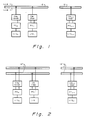
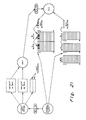
- an industrial control system in accordance with the present invention is shown in schematic form in Fig. 1 and includes n nodes or stations coupled serially to a communications bus 12.
- Each station comprises a communications module CM o -CM n-1 which in turn is coupled to a programmable controller PC o -PC n-1 .
- Each PC is provided with conventional input output devices I/O o -I/O n-1 to input data to the PC regarding the process, the data being processed by the PC to provide outputs to control the process as dictated by the program.
- there are from two to sixteen stations which are adapted to exchange from one to sixteen data or input/output words with one another via communication bus 12 which is a 124 ohm shielded twisted wire pair cable up to ten thousand feet in length.
- PC controllers can be utilized with the invention it is particularly adapted for use with the series 500 programmable controllers including models 520 and 530 manufactured and sold by Texas Instruments Incorporated.
- the communications module CM is a 3 word in - 5 word out special function, non-programmable module capable of performing high speed block transfers.
- One output word is used to determine the starting address in PC memory where the data table is to be built.
- Three input words are used to report module and network status.
- 256 words of variable (V) memory are allocated in each PC memory on the network that has a communications module. These locations in V memory form a table of data that is accessed by the CM.
- An offset word provided to the module is interpreted as a 32 bit integer value and is used to access the first word of the data table.
- the size of the data table that is built in V memory is dependent upon the choice of the number of stations on the network, if fewer than sixteen stations are used, the amount of memory written can be reduced.
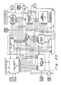
- a communications module CM uses a central processing unit CPU which in the preferred embodiments is a TMS 9995 manufactured and sold by Texas Instruments Incorporated.
- the CPU is initialized by a hardware reset which is generated by the application of power, the rising edge of early power failure or a watchdog time-out condition.
- the CPU generates the system clock from a 12 mhz crystal which is divided by 4 to give a 3 mhz CLKOUT system clock.
- the CPU supports six interrupts: reset, interrupt 1, 2, 3, 4 and NMI.
- Interrupt 1 is a communications chip interrupt.
- Interrupt 2 is a MID interrupt used to catch invalid op-codes.
- Interrupt 3 is an internal timer interrupt with a time period that is determined through software control.
- Interrupt 4 is a special function interface controller SFIC interrupt and NMI is not used by the communications module. The interrupts will be discussed in greater detail below, particularly in relation to Fig. 13.
- the communications module uses both a memory data bus and a CRU bus for the CPU.
- the memory data bus interfaces to ROM 14, RAM 16, SFIC 18 and communications chip 20.
- the CRU bus interfaces to dip switches, DIP SWT 0 and DIP SWT 1, to indicator LED Register-11 and to communications card identifier lines.
- Chip 20 is a serial communications chip (SCC) used in module CM and in the preferred embodiment is a Z8530A manufactured and sold by Zilog Inc. This chip supports serial communications over two independent channels port A and port B using bit or byte protocols at data rates up to 1 mega baud. In the preferred embodiment the data rate is 115.2K baud using asynchronous bit protocol. An external oscillator and clock multiplexer is used with chip 20 for clock generation. Chip 20 is mapped into the addressable memory space of the CPU and the two serial ports A and B drive the communication cards directly.
- SCC serial communications chip
- SFIC 18 provides the interface between the PC and the communications module.
- SFIC 18 contains 5 status registers which are programmed by the CPU and read by the PC, 16 input bytes and 16 output bytes and 1024 bytes of dual ported RAM that is used for special function communications between the communications module and the PC. A more detailed description of SFIC 18 will be furnished below.
- a watchdog timer 22 uses a free running oscillator/divider chip which has a time out period of approximately 367 milliseconds. In order to prevent expiration of the timer the CPU must clear the timer once every 300 milliseconds or faster.
- the watchdog timer is connected to the RESET input of the CPU. If the timer fires indicating that something is wrong the module will be reset. Power up diagnostics are then performed and if the fault condition no longer exists, normal operation of the module will continue.
- DIP switch 1 is an eight position switch used for test modes which will not be described herein.
- DIP switch 0 is a ten position switch and has switch definitions as set forth in Table 2.
- Position 10 relates to operating the system according to two alternate embodiments of the invention. A selection of 0 results in operation according to the first embodiment whereas a selection of 1 results in operation according to a second embodiment (to be explained infra).
- the module also includes an LED Register 11 to provide the user with an indication of its operation.
- a momentary push button (Reset) Switch 13 is used to effect execution of the reset or self-test based on the position of a toggle switch 15 movable between run and test positions.
- the operating system software controls the initializaiton of the module, network interface, PC interface and fault recovery.
- the network interface software is primarily interrupt driven but also has sections called by the execution loop.
- the start and end flags are HDLC flags (HEX 7E).
- the control/address field contains both control and station address information and comprises one byte.
- the message field comprises up to sixteen words of data.
- the CRC comprises two bytes of data that provide a method of data verification.
- the module uses the CCITT polynomial (International Consultative Committee on Telephone and Brass) preset to ones for CRC calculation.
- the order of transmission of the bytes within a frame is from least significant bit (LSB) to most significant bit (MSB). As used herein, the most significant bit is the lowest numbered bit in the byte.
- control/address field format is shown in Fig. 6.
- C0-C3 and the HEX designation form a control code defined in Table 3.
- A0-A3 form an address field that indicates the source of data broadcasts or identifies the station which has been given a time slot.
- Fig. 7 The format of the message field is shown in Fig. 7 in which Data Words 0-15 define the data that is broadcast to all active units on the network.
- the communications modules CM are capable of operating in one of three different modes, as an active monitor (AM), as a passive monitor (PM) and as a non-monitor (NM).
- AM active monitor
- PM passive monitor
- NM non-monitor
- Active monitors are characterized in that they supervise network communications and allocate time for the other CM's to broadcast as well as broadcasting their own data. There is only one active monitor on a network in normal operation and it is assigned by means of dipswitch DIP SWT 0. This is a switch selected AM or SAM and it never assumes any other mode of operation.
- Passive monitors are characterized in that they monitor the network and become active if the original active monitor fails. This condition is detected when the PM receives no transmissions for an interval of time called the Dead Bus Timeout (DBT) value.
- DBT Dead Bus Timeout
- a passive monitor becomes a non-monitor when it hears another passive monitor on the network, when it receives command C or when it is reset.
- a passive monitor that becomes an active monitor (PAM) returns to being a passive monitor when instructed to do so by the switch selected active monitor. The passive monitor broadcasts its data when so instructed by the active monitor.
- PAM active monitor
- Non-monitors are characterized in that they broadcast their data only when commanded (enabled) by an active monitor.
- a non-monitor becomes a passive monitor when so assigned by an active monitor but cannot become active monitor directly.
- each communications module executes a cycle reading all its own switches. Once this has been accomplished, the module will not reconfigure until the next time a power up occurs or the module is reset.
- the module which is designated as the switch selected active monitor after completeing its self-diagnostics begins to monitor the network and determines which of the n possible modules are present in the network and assign a non-monitor node the role of passive monitor.
- the active monitor determines which nodes are present by issuing a polling command which is addressed in turn to each node. This command using the format shown in Fig 5. and using a HEX control field of A or E instructs that node to broadcast its data messages to all other nodes on the network. The length of these data messages depends on positions 5-8 of DIP SW 0 selected for each module.
- the poll command frame is very short since there are no data words included in the transmission.
- the active monitor includes it in a list of active nodes which are to be granted the right to transmit on a equal priority basis. All other nodes create a list of active nodes based upon the polling for use as an indicator of the network status.
- the active monitor When the list of active nodes is built, the active monitor begins issuing commands to each node in turn, directing the nodes to broadcast their data. This command is called a time slot assignment or allocation (TSA) and has the same format as the polling command frame and therefore is a very short time frame. The active monitor broadcasts its own data in turn.
- TSA time slot assignment or allocation
- the active monitor maintains the network as a part of its normal operation. In addition to granting time slots for data broadcast to each node address contained on the active list, the active monitor polls each node address (including those not on the active list) for the purpose of adding and removing nodes. If a new node is added to the network the active monitor will add the new node's address after polling the address and receiving a response. A node which is removed from the network is deleted from the active list when it fails to respond to the poll addressed to that node.
- the active monitor issues a poll to each of the n possible network addresses in a cyclical basis.
- the active monitor maintains a list of active nodes and a pointer to the node address which is to receive the poll.
- the list of active node addresses and the pointed to node address are combined to form a list of the nodes to be granted a time slot or a poll.
- the active monitor then changes the pointer to point to the next node address to be polled and modifies the list of active node addresses if there has been a change.
- the active monitor When the active monitor issues either a TSA or a poll to the node address of the passive monitor and the passive monitor fails to respond, the active monitor immediately reassigns the roll of passive monitor. The poll is still used to determine whether the node is to be removed from the active list.
- Fig. 8 shows a start up scan with the SAM address of 0 and other units active on the network of 3, 4 and 6.
- the top line includes the commands and address fields issued by the active monitor while the lower line includes the command and address fields of the responding units.
- the active monitor first has broadcast its own data (control 8) and then has tried to assign the roll of passive monitor using command E to nodes 1 and 2 before successfully assigning it to node 3, node 3 responding with control 4. Thereafter active monitor issues command A (see also Fig. 15 - Do Poll truth chart) which is a poll command directing each non-monitor to broadcast its data and nodes 4 and 6 in turn broadcast their data using control 0.
- Fig. 9 see also the truth chart for single media scan shown in Fig. 16
- three scans during normal operation are shown with the active monitor starting in the first scan its cyclic polling with node 5 and thereafter broadcasting its own data and issuing time slot grants (see also Fig. 17 - DO TSA truth chart) to non-monitors (command 8) with passive monitor 3 responding using control 4 and non-monitors 4 and 6 responding using control 0.
- the following scans are identical except for the address of the poll node being stepped through other nodes, i.e., nodes 6 and 7.
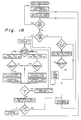
- Fig. 10 illustrates a situation in which the passive monitor, node 3, does not respond to its time slot allocation.
- the active monitor has issued a TSA (control 8) to node 3 (see also Fig. 17) and when it does not respond within the receive time out interval, the AM issues a command to node 3 attempting to reassign it as passive monitor (command E) in case its response was missed due to interference and failing to receive a response issues the same command to node 4 which responds accepting its roll as the new passive monitor and broadcasting its data.
- TSA control 8
- Fault tolerance is provided in the single medium embodiment of the invention in protecting against single node failures or cable breaks which would normally halt network operations.
- the active monitor assigns each node (starting with its own node address plus one and wrapping around from n-1 to zero) the role of passive monitor.
- the first node to respond accepts the role of passive monitor.
- the network can be arranged for optimum fault tolerant protection due to cable breaks. For example, if the switch selected AM has an address of 0 and is located at one end of the network the node with the address 1 should be located at the opposite end of the network. In the event that the active monitor fails the passive monitor would assume the role of active monitor (PAM) and assign another node the role of passive monitor.
- PAM active monitor
- Collisions can also occur when the active monitor node fails and the passive monitor takes over as active monitor.
- the network protocol directs that the SAM listen for network activity. If no activity is detected, then it initiates network communications. If such activity is detected, the SAM waits for the PAM to issue a poll to the address of the SAM. when this occurs, the SAM responds by issuing a command C which cancels all prior assignments of the roll of passive monitor and assigns the node which issued the poll command the role of passive monitor. Network communications then proceed in normal fashion.
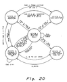
- nodes When nodes first power up they will be either non-monitors, NM, state V or the switch selected active monitor, SAM, state I. In normal operation there is only one AM and no transmissions take place until the SAM initiates them. Thus the dead bus time out will occur and the SAM will transition to state II, start communications and assign a passive monitor PM causing an NM to transition from state V to state IV. No further state transitions occur unless something goes wrong.
- the PAM assigns a new PM as before, causing a V to IV state transition in the node assigned.
- the network then runs normally, minus one node.
- the SAM waits until it receives a poll to its own address and responds with a command C. This causes a II to IV transition in the PAM, cancels the other PM while the SAM moves to state II and begins communications.
- the SAM immediately assigns a new PM and cancels the other PM.
- Command 4 always causes a IV to V state transition in all PMs except the one to which the command was sent, leaving only that node as PM. Again the network is operating normally.
- each node Since each node has a unique address there is less danger of a collision when an AM receives another AMs request to the receiver's own address so the receiving unit will resolve monitorship with its response at that time.
- CM communications modules
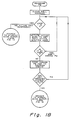
- the communications modules CM are provided with dual ports and if the DIP switch 0 position 10 of DIP SWT 0 is selected as 1, the modules will be operable with redundant media.
- port A of communications chip 20 is coupled through a local line connector block to one medium of communications bus 12' and port B of chip 20 is coupled through a similar block to the other medium of the twisted pair cable.
- the several CMs (CM0-CM n-1 ) are serially connected to each medium of the bus as in Fig. 1. Operation of this embodiment is similar to that of the first embodiment and the description will be limited to differences between the embodiments.
- the communications modules are either active or non-active, there being no passive monitor mode of operation.
- the active monitor is selected by DIP SWT 0 (position 9) and only one active monitor can be selected for a given network.
- the active monitor determines which nodes are active on each medium and uses the medium with the greatest number of active nodes as the channel on which communications are directed (or channel A if the number of nodes on each channel are equal).
- a poll is issued on both network media. Should a node whose address is contained in the active list fail to respond to a TSA, the active monitor immediately polls the node on both media. If the node still does not respond, the active monitor continues the cycle by returning to the primary medium.
- the active monitor concludes that a failure in the primary medium has occurred and switches to the secondary medium.
- fault tolerance by means of the dual media interface protects against a cable fault and against driver-receiver failure at a node.
- communication is maintained by switching to the alternative medium.
- Each node maintains a list of active nodes for each medium based on the response to the poll issued by the active monitor. This list can be used to help troubleshoot the network or to indicate a failure condition so that appropriate action can be taken to avoid loss of network communications. Removal of a node from a dual media network will not cause the active monitor to switch operation to the alternate medium since the balance of the number of active nodes is not upset by removing the node from both media interfaces.
- Fig. 11 With reference to Fig. 11 (see also truth chart for dual media scan shown in Fig. 19) two normal scans are shown for an AM having an address of 0 and three other units on the network 3, 4, and 6. It will be noted that the poll command A is sent on both media.
- node 4 fails to respond to its TSA on channel A so that a poll command is sent on channel A and then on channel B. A response in channel B causes a media changeover to channel B for all the nodes.
- the network communication interrupt structure will be described with particular reference to Fig. 13.
- the system hardware is configured such that the serial communications chip 20 (SCC) generates a level 1 interrupt when it receives a character or when it finishes transmitting a character.
- a receive interrupt e.g. Fig. 13 b , starts the next transmission in order to have fast, deterministic communication.
- All communications are interrupt driven. This presents a problem in two cases; how to start the system, and how to get back to the communications software if an expected reception does not occur.
- the hardware timer is used to time this delay so the software is free during the delay interval.
- the hardware timer (Fig. 13 c ) will generate a level 3 interrupt when the programmed interval expires.
- the level 1 communications code must be accessed.
- the invention accomplishes direct branching to level 1 by creating "false interrupts.”
- the normal interrupt in the CPU automatically changes the interrupt mask to the proper level and does a call to the interrupt vector. Any return after an interrupt is performed automatically and restores the interrupt mask to its previous value, which was saved by the CPU hardware.
- the interrupt mask is changed to the correct values by software before and after a call to the routine in the other interrupt level. This allows level 1 code to be started from the OS or accessed by the timer interrupt service routine (ISR).
- ISR timer interrupt service routine
- each module initializes itself and begins communications with the PC.
- the module which checks this will mask all interrupts and call (false interrupt) the startup supervisor in the AM unit only.
- the start-up supervisor calls the Do Poll module (Fig. 15), which sets up the hardware timer to do a delay and stores the vector to which it should branch at the end of the delay. Then Do Poll returns to the timeout checker, which restores the interrupt mask and returns to the executive. The first false interrupt is complete.
- a normal level 3 interrupt passes control to the timer ISR. This routine masks all interrupts and calls to the vector stored in Do Poll. Do Poll then sends the first byte of the command to the SCC 20 and returns to the timer ISR, which restores the interrupt mask to the level 3 value and returns to the OS. The second false interrupt is complete.
- SCC 20 When SCC 20 has shipped the byte out of its input buffer, it will generate a level 1 interrupt. The transmit ISR will load the next byte and return. This continues until the last byte is sent. The transmit ISR then initializes SCC 20 to receive, sets up the timer to do a receive timeout, and returns.
- the timer If the receive does not occur within the timeout period, the timer generates a level 3 interrupt which does a false interrupt to the startup supervisor (the address for this branch was saved when Do Poll was called) with a flag telling the supervisor that the unit did not respond. The supervisor then calls Do Poll to send a poll to the next unit. When Do Poll sets up the delay and returns, it returns to the timer ISR, which corrects the interrupt mask and returns to the OS. The next poll will take the same paths as the first.
- the SCC If the receive does occur within the timeout period, the SCC generates a level 1 interrupt which branches to the receive ISR.
- This routine stores the first data byte and sets a flag telling the timer ISR to simply return to the OS when the timeout internal expires. The receive ISR then returns. Each byte received causes this process to repeat until the end flag indicates the end of the message. Then the receive ISR branches to the AM receive processor, which stores the data if the CRC is good and branches back to the start-up supervisor (to the same location that the timer ISR branches on timeouts) with the response received flag set. If the CRC is bad, the response receive flag is cleared. Control does not return to the OS until the next send delay is programmed and Do Poll returns.
- the scan supervisor is accessed in the same fashion as the start-up supervisor, and the Do TSA module (Fig. 17) is accessed like the Do Poll module.
- NM/PM units no start-up is required.
- the first AM command received goes through the receive ISR to the NM/PM data processor, which determines if it should store data, respond, or do nothing. If the command requires a response, the data processor sends the first byte and returns, leaving the rest to the transmit ISR.
- SCC 20 is initialized to receive. The timer is not programmed by NM/PM units. Note that PMs become AMs in the dead bus checker if the AM has stopped communicating. Otherwise there are no false interrupts in NM/PM units.
- Multiple buffers allow the asynchronous operation of the network interface and the PC interface.
- the operation of the buffers for data directed from the network to a PC and from a PC to the network are shown in Fig. 21.
- Data frames from the network are loaded in a Receive Buffer until the CRC and length are verified.
- the pointer to that Receive Buffer is swapped for the pointer to the old node N buffer.
- the New Data Flag is then set for the new node telling the operating system that new data is available. If the CRC or length is not good, then no buffer swap takes place, the bad data is not used and the same buffer is used for the next frame received.
- the operating system When the operating system begins to fill the SFIC 18 for the PC transfer, it first checks the New Data Flag for each node. If the flag is set the buffer pointers are swapped between the operating system and the receive buffer handler and the flag is cleared keeping the most recent data in the SFIC chip 18.
- the operating system When data is read from the SFIC RAM the operating system writes the data into one of te two transmit buffers. Then the operating system checks to see if the transmitter is using the transmit buffer and waits until the buffers are not busy. Then the operating system swaps the transmit routine buffer with its own giving the routine access to the new data the next time it is needed.
- buffer pointers are swapped between the interrupt service routine (ISR) and the operating system and no data is copied or moved around.
- Fig. 22 shows a block diagram of the local line card circuitry.
- Serial data to or from the serial communications controller SCC-20 is buffered and isolated through optically coupled isolators OCI.
- the transmit data from the isolator is converted from voltage source drive to current source drive by dual tri-state differential line drivers and goes through a protection circuit (to handle spikes, which it routes to the power supply and ground) to the transmission lines.
- Receive data is attentuated 6 dB by a high impedance attentuator, amplified and fed to the SCC-20 through another opto-isolator.
- Each local line card is biased due to the possibility of random noise being read as a flag. That is, in the dual media embodiment a break in the cable could cause an interrupt on the channel attached to the break even though the module was communicating on the other channel. The internal bias obviates this problem.
- a jabberstop circuit which prevent faults due to failure in the control of line drivers from bringing down the network. If the transmission of a single frame exceeds a selected number of bits, in the preferred embodiment 4,096 bits, the circuit will disable the drivers.
- the outputs of the line drivers are connected to the two wires of the shielded twisted pair communications bus labeled LLM+ and LLM-.
- the line driver sources current to the LLM+ line and sinks current from the LLM- line for one signal state and the opposite for the other.
- An isolated ⁇ 5 volt unregulated power supply provides power for the line drivers and receivers.
- Fig. 18 shows a block diagram of the special function interface controller, SFIC 18 which in the preferred embodiment is a digital NMOS integrated circuit.
- SFIC includes A Port Control Decoder 18-1 coupled to the PC and B Port Control Decoder 18-2 coupled to the communications module CM; interrupt register and clear 18-5 to generate interrupts; control register 18-4 which allows B Port to know the relevant mode of operation; a 1K x 8 RAM 18-9 which formulates read and write requests to and from the PC; normal input/output and status registers 18-6, eight one word registers accessable by both ports with input words to the PC to report status and output words to control variable memory starting address; command byte 18-7 used to set up the relevant mode of operation (write or read) in 18-9 RAM; B Port Address decoder 18-3 and RAM Address Controller 18-8.
- the controller provides timing, decoding memory and control functions to perform block transfers between the communications module and the PC and takes the form of a forty pin dual in line package.
- Controller 18 enables the CM to read and write data from a series 500 PC providing logic to allow up to eight data blocks of 128 bytes each to be transferred consecutively between the internal 1K x 8 RAM, 18-9, and a series 500 PC.
- the controller provides the address control for the on board RAM while the starting block address is configurable from outside the controller.
- Controller 18 also provides five 8-bit status registers to identify the type of special function in which it resides which are configured from outside the controller.
- Controller 18 provides decode logic to interpret control bytes from a Series 500 PC and respond properly to subsequent control signals and execute the directed transfers.
- Controller 18 provides decode logic to interpret control bytes from a Series 500 PC and respond properly to subsequent control signals and execute the directed transfers. Controller 18 also provides logic to recognize interrupt conditions and forward these to the SF controlling devices, the CPU. In addition, the controller provides logic to accommodate a configurable normal I/O capability of up to eight Series 500 I/O points, either input or output, word or discrete.
- Controller 18 provides two separate control interface ports A and B allowing two external devices (the CPU and the PC) independent control of reading and writing to internal registers and the internal 1K x 8 RAM 18-9.
- the A PORT interfaces to the PC and consists of an eight bit data bus A:D0 through A:D7(A PORT DATA BUS) bidirectional data lines over which data control or status information is transferred to and from the controller, a four bit channel address A:CA0-A:CA3, binary encoded lines which indicate the particular channel to be accessed used for reading various status register or for reading or writing normal word I/O data bytes, and six control signals.
- a low active signal on A:CS* (A PORT CHIP SELECT causes the controller to execute a data transfer over the A PORT DATA BUS.
- a control signal to controller 18 on A:ST*(A PORT DATA-STATUS SELECT) indicates whether the information to be transferred over the A PORT DATA BUS is data or status.
- a control signal to the controller 18 on A:WE* indicates which direction to transfer the information on the A PORT DATA BUS.
- a control signal on A:IOC* indicates that the normal I/O cycle is complete on A PORT.
- a control signal on A:IOD (A PORT I/O DISABLE) disables normal outputs.
- An output signal from controller 18 on A: IOFAIL* informs the A PORT controller 18-2 that immediate services is requested. This is reset by reading the status register contents.
- the B PORT provides signals that interface to the controlling CPU within the communications module CM and comprises B:D0-B:D7 (B PORT DATA BUS), eight data lines over which the controller 18 data and control is passed, B:AD0-B:AD6 (B PORT ADDRESS), seven address lines that identify the source or destination of B PORT data and control information and the following control signals.
- a signal on B:CS* (B PORT CHIP SELECT) enables controller 18 to interpret B PORT control signals.
- a control signal on B:WE* pulses low with B:CS* to write to controller 18.
- the master reset for the chip is active when both B:RD* and B:WE* are held low.
- a control signal on B:RD* (B PORT READ ENABLE) pulse low with B:SC* to read from controller 18.
- the master reset for the chip is active when both B:RD* and B:WE* are held low.
- a continuous clock signal, 2.5 mhz to 4 mhz is provided at B:CLK (B PORT CLOCK INPUT).
- An output signal on B:1NT* (B PORT INTERRUPT) informs the B PORT controller that its attention is needed.
- the cause of the interrupt is held in a readable interrupt register.
- the B PORT 18-2 control decode decodes the seven B PORT address lines whenever the B:CS* pulses low and functions based upon the HEX address code.
- the A PORT control decode 18-1 uses the conditions on the A PORT lines A:WE* and A:ST* to determine what action is required when A:CS* pulses low and functions based on these control lines and prior history.
- Controller 18 performs data block transfers between RAM 18-9 and A PORT and data transfers between the normal I/O registers 18-6 and A PORT.
- the RAM address controller 18-8 drives the address lines of RAM 18-9 according to the Control Register 18-4 set up.
- Interrupt logic is provided by register 18-5 which are passed to B PORT by setting in appropriate bit an the register.
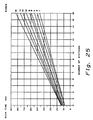
- Figs. 24 and 25 show curves indicating network performance that is achieved by the broadcast bus for various numbers of nodes and numbers of words being transmitted per node, Fig. 24 showing performance for the first embodiment and Fig. 25 for the second embodiment. These curves reflect the values chosen for message timeouts and active monitor delays between received message and the next time slot assignments.
- the protocol employed in the invention includes both initialization and maintenance of the network in a manner which resolves conflicts among nodes for the right to transmit while assuring each node the opportunity to transmit its messages and providing for the addition and removal of nodes without conflict.
- the two embodiments provide a choice of fault tolerance which can be selected to best meet a particular industrial process and factory environment in which the network will be employed.
Claims (23)
- Steuersystem für verteilte Prozesse mit einem Kommunikationsbus (12), mehreren programmierbaren Prozeßsteuereinheiten (PCo, PC₁, PCn-1), die jeweils über Kommunikationsmodulmittel (CMo, CM₁, CMn-1) mit dem Bus gekoppelt sind, wobei die Kommunikationsmodulmittel die Übertragung eng gekoppelter Informationen unter den Steuereinheiten steuern, wobei jede programmierbare Prozeßsteuereinheit abhängig von Eingangssignalen (I/O₀, I/On-1), die sich auf den Prozeß beziehen, Ausgangssignale zum Steuern ausgewählter Geräte erzeugen, die den Prozeß bewirken, wobei jedes Kommunikationsmodulmittel über den Bus Daten senden und empfangen kann und als aktiver Monitor arbeiten kann, der die ausschließliche Steuerung über die Datenübertragungsaktivität auf den Bus ausübt, wobei jedes Kommunikationsmodulmittel ferner als Nicht-Monitor arbeiten kann, wobei während des Betriebs an jedem Zeitpunkt immer nur ein aktiver Monitor vorhanden ist und im Betrieb die Nicht-Monitore nur dann senden, wenn sie durch den aktiven Monitor dazu freigegeben sind, dadurch gekennzeichnet, daß die Nicht-Monitore Daten zu allen anderen Kommunikationsmodulmitteln senden können, daß der aktive Monitor ausschließlich die Steuerung über die Sendeaktivität auf den Bus ausübt, indem er jedem der Kommunikationsmodulmittel Zeitschlitze zuteilt und jedes der anderen Kommunikationsmodulmittel freigibt, Daten während dieses Zeitschlitzes auf den Bus zu senden, und daß jedes Kommunikationsmodulmittel auch als passiver Monitor arbeiten kann, der zusätzlich zum Aussenden von Daten zu allen anderen Modulmitteln bei einer solchen Freigabe durch den aktiven Monitor auch die Sendeaktivität überwacht und nach einer ausgewählten Zeitdauer ohne Sendeaktivität zum aktiven Monitor wird, wobei das System Zeitsteuermittel enthält, die eine Anzeige des Ablaufs der ausgewählten Zeitdauer liefern, und Mittel enthält, die einem der Kommunikationsmodulmittel, das nicht der aktive Monitor ist, als passiven Monitor zuordnen.
- System nach Anspruch 1, bei welchem der aktive Monitor vorherbestimmt ist.
- System nach Anspruch 1, bei welchem jedes Kommunikationsmodulmittel als aktiver Monitor arbeiten kann und bei welchem die Anordnung Mittel enthält, um eines der Modulmittel als einen vom Benutzer gewählten aktiven Monitor auszuwählen.
- System nach Anspruch 1, Anspruch 2 oder Anspruch 3, bei welchem die Steuereinheiten Speichermittel und Mittel zum selektiven Auswählen der Plazierung der eng gekoppelten Informationen in den Speichermitteln enthalten, so daß sie von und zu den Kommunikationsmodulmitteln zugänglich sind.
- System nach einem der Ansprüche 1 bis 4 zum Auswählen aus eins bis sechzehn Wörtern, die die Kommunikationsmodulmittel senden können.
- System nach einem der Ansprüche 1 bis 5 mit Kommunikationstreibermitteln zum Senden von Informationen in Form von Nachrichtenrahmen auf dem Kommunikationsbus und ferner mit Schaltungsmitteln zum Deaktivieren der Kommunikationstreibermittel für den Fall, daß der Nachrichtenrahmen eine gewählte Länge überschreitet.
- System nach einem der Ansprüche 1 bis 6, bei welchem die Kommunikationsmodulmittel Wortbestätigungsmittel enthalten, die gegebene Informationen bestätigen können, die von einem Kommunikationsmodulmittel empfangen werden, ohne daß der Empfang dieser gegebenen Informationen bestätigt wird.
- System nach einem der Ansprüche 1 bis 7, bei welchem jedes Kommunikationsmodulmittel Schaltermittel zum Auswählen einer anderen Anzahl von Datenwörtern für jedes Modulmittel zum Senden über das Netz während seines Zeitschlitzes enthält.
- System nach Anspruch 8, bei welchem die Schaltermittel jede Anzahl von Datenwörtern von eins bis sechzehn auswählen können.
- Verfahren zum Steuern von Netz-Buskommunikationen für eng gekoppelte Informationen unter verteilten programmierbaren Steuereinheiten (PCo, ... PCn-1), die an einen Kommunikationsbus (12) angeschlossen sind, wobei jede Steuereinheit an einen Knotenpunkt über ein Kommunikationsmodulmittel (CMo, ... CMn-1) mit dem Kommunikationsbus gekoppelt ist, das Daten über den Kommunikationsbus senden und empfangen kann, wobei das Kommunikationsmodulmittel als aktiver Monitor arbeiten kann, der das Netz abtastet und die ausschließliche Steuerung über die Sendetätigkeit auf dem Netz ausübt, und als Nicht-Monitor arbeiten kann, der bei Freigabe durch den aktiven Monitor Daten über den Bus sendet und empfängt, und bei welchem nur eines der Kommunikationsmodulmittel als aktiver Monitor zum Steuern der Übertragungen auf den Bus bestimmt wird, dadurch gekennzeichnet, daß die Nicht-Monitore Daten auf den Bus senden, wenn sie durch den aktiven Monitor freigegeben werden, wobei der aktive Monitor bei Aktivierung bei seinem ersten Netzabtastvorgang eine Abfrage an jedes an den Bus angeschlossene Kommunikationsmodulmittel sendet, um festzustellen, welche Kommunikationsmodulmittel eingeschaltet und aktiv am Bus sind, wobei die abgefragten Kommunikationsmodulmittel freigegeben werden und ihre Daten auf den Kommunikationsbus senden, wobei der aktive Monitor eine Liste der Kommunikationsmodulmittel erstellt, die auf die Abfrage als am Bus aktives Kommunikationsmodulmittel antworten, wobei der aktive Monitor während jedes normalen folgenden Abtastvorgangs einen Teil der Abtastung für jedes Kommunikationsmodulmittel, das in der Liste enthalten ist, als Zeitschlitz zuordnen (TSA) zuweist und die TSA der Reihe nach zu jedem in der Liste enthaltenen Kommunikationsmodulmittel sendet, wobei das die TSA empfangende Kommunikationsmodulmittel freigegeben wird und seine Daten über den Kommunikationsbus zu jedem anderen Kommunikationsmodulmittel am Bus sendet.
- Verfahren zum Steuern von Netz-Buskommunikationen für eng gekoppelte Informationen nach Anspruch 10, bei welchem n Kommunikationsmodulmittel mit dem Kommunikationsbus gekoppelt sind, und ferner mit dem Schritt des Sendens einer Abfrage an ein einziges, jedoch anderes Kommunikationsmodulmittel in jedem Netzabtastvorgang, so daß alle Kommunikationsmodulmittel, die an das Netz angeschlossen sind, einmal pro n Netzabtastvorgängen geprüft werden, damit die Liste der am Netz aktiven Kommunikationsmodulmittel kontinuierlich aktualisiert wird.
- Verfahren zum Steuern von Netz-Buskommunikationen für eng gekoppelte Informationen nach Anspruch 10 oder 11, bei welchem die Kommunikationsmodulmittel auch als passiver Monitor arbeiten können, der zusätzlich zum Aussenden von Daten zu allen anderen Kommunikationsmodulmitteln am Netz im freigegebenen Zustand auch zu einem aktiven Monitor werden können, der die ausschließliche Überwachungssteuerung über die Sendeaktivität am Netz ausübt, ferner enthaltend den Schritt, den aktiven Monitor zu veranlassen, eines der übrigen mit dem Netz gekoppelten Kommunikationsmodulmittel als passiven Monitor zu bestimmen, wobei der passive Monitor das Netz kontinuierlich auf die Anwesenheit einer Sendeaktivität überwacht und wobei der passive Monitor jede Periode zeitlich steuert, in der keine Sendeaktivität vorliegt, und bei Auftreten der Abwesenheit einer solchen Sendeaktivität für eine ausgewählte Zeitdauer die ausschließliche Überwachungssteuerung über die Sendeaktivität des Netzes als aktiver Monitor übernimmt.
- Verfahren zum Steuern von Netz-Buskommunikationen für eng gekoppelte Informationen nach Anspruch 12, bei welchem alle im Netz aktiven Kommunikationsmodulmittel eine Liste aller anderen im Netz aktiven Kommunikationsmodulmittel enthalten, und ferner enthaltend den Schritt, bei dem der passive Monitor, der die Steuerung der Sendeaktivität des Netzes übernommen hat, eines der übrigen im Netz aktiven Kommunikationsmodulmittel als passiven Monitor bestimmt.
- Verfahren zum Steuern von Netz-Buskommunikationen für eng gekoppelte Informationen unter verteilten programmierbaren Steuereinheiten gemäß Anspruch 12 oder 13, enthaltend den Schritt, daß der bestimmte aktive Monitor beim Entfernen aus dem Netz und beim Reaktivieren am Netz am Senden gehindert wird, bis das erste von den zwei folgenden Ereignissen eintritt: erstens: es tritt eine ausgewählte Zeitperiode auf, in der keine Kommunikationen am Bus gesendet werden, und zweitens: der bestimmte aktive Monitor empfängt eine an ihn gerichtete Abfrage, wobei an diesem Zeitpunkt der bestimmte aktive Monitor die Überwachungssteuerung über das Netz wieder aufnimmt.
- Verfahren zum Steuern von Netz-Buskommunikationen für eng gekoppelte Informationen unter verteilten programmierbaren Steuereinheiten nach Anspruch 12, 13 oder 14, ferner enthaltend den Schritt, daß der aktive Monitor die Rolle des passiven Monitors wieder einem anderen Modul zuordnet, falls der zuvor zugeordnete passive Monitor nicht auf seine TSA oder Abfrage antwortet.
- Verfahren zum Steuern von Netz-Buskommunikationen für eng gekoppelte Informationen unter verteilten programmierbaren Steuereinheiten nach Anspruch 15, enthaltend den Schritt, daß das als passiver Monitor erneut zugeordnete Kommunikationsmodulmittel seine Zuordnung bestätigt und alle anderen passiven Monitorzuordnungen aufhebt, so daß nur ein Kommunikationsmodulmittel als passiver Monitor arbeitet.
- Verfahren zum Steuern von Netz-Buskommunikationen für eng gekoppelte Informationen unter verteilten programmierbaren Steuereinheiten nach einem der Ansprüche 12 bis 16, enthaltend den Schritt, daß beim Empfang von Daten durch einen aktiven Monitor von einem anderen aktiven Monitor der empfangende aktive Monitor am Senden gehindert wird, bis das erste der zwei folgenden Ereignisse eintritt: erstens: es tritt eine ausgewählte Zeitperiode ohne das Senden von Kommunikationen am Bus auf; und zweitens: der empfangende aktive Monitor empfängt eine an ihn adressierte Abfrage, wobei an diesem Zeitpunkt der empfangende aktive Monitor die Überwachungssteuerung über das Netz wieder aufnimmt, während der sendende aktive Monitor ein passiver Monitor wird.
- Verfahren zum Steuern von Netz-Buskommunikationen für eng gekoppelte Informationen nach einem der Ansprüche 10 bis 17, bei welchem der Kommunikationsbus Doppelmedien enthält und jedes Kommunikationsmodulmittel zwei Anschlüsse aufweist, wobei einer des Paars jedes Kommunikationsmittels an das eine Medium und der andere des Paars jedes Kommunikationsmodulmittels an das andere Medium angeschlossen ist, wobei der Schritt des Aussendens einer Abfrage das Senden der Abfrage zu jedem Anschluß jedes Kommunikationsmodulmittels umfaßt, wobei das Nicht-Monitor-Kommunikationsmodulmittel für den Empfang von Informationen auf beiden Medien vorbereitet ist und das Nicht-Monitor-Kommunikationsmodulmittel, das abgefragt wird, durch die Abfrage für ein Antworten durch Aussenden seiner Daten über das gleiche Medium freigegeben wird, auf dem es die Abfrage empfangen hat, wobei der aktive Monitor die Anzahl der Antworten auf jedem Medium vergleicht und weitere Aussendungen von allen aktiven Kommunikationsmodulmitteln auf das Medium lenkt, an dem die größte Anzahl von Antworten empfangen wurde.
- Verfahren zum Steuern von Netz-Buskommunikationen für eng gekoppelte Informationen unter verteilten programmierbaren Steuereinheiten nach einem der Ansprüche 10 bis 18, enthaltend den Schritt der Wiederzuordnung eines TSA zum nächsten Kommunikationsmodulmittel in der Liste, wenn ein Kommunikationsmodulmittel seine Daten nicht innerhalb einer gegebenen Zeitablaufperiode aussendet, so daß die wirksame Nutzung des Netzabtastvorgangs optimiert wird.
- Verfahren zum Steuern von Netz-Buskommunikationen für eng gekoppelte Informationen unter verteilten programmierbaren Steuereinheiten nach einem der Ansprüche 10 bis 19, enthaltend den Schritt, daß jedes Kommunikationsmodulmittel von ihm empfangene Informationen bestätigt und jeden aktiven Monitor aus der Überwachungssteuerung des Netzes beim Auftreten einer ausgewählten Anzahl aufeinanderfolgender Informationsbestätigungen aus dem Netz entfernt.
- Verfahren zum Steuern von Netz-Buskommunikationen für eng gekoppelte Informationen unter verteilten programmierbaren Steuereinheiten nach einem der Ansprüche 10 bis 20, enthaltend den Schritt, daß jeder Knotenpunkt eine Liste aktiver Module am Netz erstellt und aufrechterhält.
- Verfahren zum Steuern von Netz-Buskommunikationen für eng gekoppelte Informationen gemäß einem der Ansprüche 10 bis 20, bei welchem jedes Kommunikationsmodulmittel eine ausgewählte Anzahl von Datenwörtern während seiner Zeitschlitzzuordnung unabhängig von der Anzahl von Wörtern aussendet, die für andere Kommunikationsmodulmittel am Netz ausgewählt sind.
- Verfahren zum Steuern von Netz-Buskommunikationen für eng gekoppelte Informationen gemäß einem der Ansprüche 10 bis 22, bei welchem die für jeden Abtastvorgang des Netzes vom aktiven Monitor benötigte Zeit von der Anzahl von Datenwörtern abhängt, die zum Aussenden durch jedes im Netz aktive Kommunikationsmodulmittel ausgewählt ist.
Applications Claiming Priority (2)
| Application Number | Priority Date | Filing Date | Title |
|---|---|---|---|
| US719174 | 1985-04-03 | ||
| US06/719,174 US4680753A (en) | 1985-04-03 | 1985-04-03 | System and method for controlling network bus communications for input-output interlocking information among distributed programmable controllers |
Publications (3)
| Publication Number | Publication Date |
|---|---|
| EP0200365A2 EP0200365A2 (de) | 1986-11-05 |
| EP0200365A3 EP0200365A3 (en) | 1989-06-28 |
| EP0200365B1 true EP0200365B1 (de) | 1993-09-22 |
Family
ID=24889046
Family Applications (1)
| Application Number | Title | Priority Date | Filing Date |
|---|---|---|---|
| EP86302360A Expired - Lifetime EP0200365B1 (de) | 1985-04-03 | 1986-03-27 | System und Verfahren zur Busübertragungssteuerung für eng gekoppelte Nachrichten zwischen verteilten programmierbaren Steuergeräten |
Country Status (4)
| Country | Link |
|---|---|
| US (1) | US4680753A (de) |
| EP (1) | EP0200365B1 (de) |
| JP (1) | JPH0624371B2 (de) |
| DE (1) | DE3689052T2 (de) |
Cited By (1)
| Publication number | Priority date | Publication date | Assignee | Title |
|---|---|---|---|---|
| CN1112784C (zh) * | 1996-03-25 | 2003-06-25 | 太阳微系统有限公司 | 用于在下载的程序之间建立保密对等通信的系统和方法 |
Families Citing this family (72)
| Publication number | Priority date | Publication date | Assignee | Title |
|---|---|---|---|---|
| JPS582904A (ja) * | 1981-06-27 | 1983-01-08 | Omron Tateisi Electronics Co | プログラマブル・ロジツク・コントロ−ラ |
| DE3424866C2 (de) * | 1984-07-06 | 1986-04-30 | Messerschmitt-Bölkow-Blohm GmbH, 8012 Ottobrunn | Verfahren und Anordnung zur Übertragung von Daten, insbesondere in einem Flugzeug |
| DE3534216A1 (de) * | 1985-09-25 | 1987-04-02 | Bayerische Motoren Werke Ag | Datenbussystem fuer fahrzeuge |
| US4747130A (en) * | 1985-12-17 | 1988-05-24 | American Telephone And Telegraph Company, At&T Bell Laboratories | Resource allocation in distributed control systems |
| US5007013A (en) * | 1986-04-01 | 1991-04-09 | Westinghouse Electric Corp. | Bidirectional communication and control network with programmable microcontroller interfacing digital ICS and controlled product |
| GB8612396D0 (en) * | 1986-05-21 | 1986-06-25 | Hewlett Packard Ltd | Chain-configured interface bus system |
| JP2761872B2 (ja) * | 1987-03-20 | 1998-06-04 | 株式会社日立製作所 | 多元情報交換方法及びそのための装置 |
| US5241627A (en) * | 1987-04-09 | 1993-08-31 | Tandem Computers Incorporated | Automatic processor module determination for multiprocessor systems for determining a value indicating the number of processors |
| EP0286235B1 (de) * | 1987-04-09 | 1996-10-16 | Tandem Computers Incorporated | Automatische Bestimmung der Anzahl von Prozessormodulen für Multiprozessorsysteme |
| US4933846A (en) * | 1987-04-24 | 1990-06-12 | Network Systems Corporation | Network communications adapter with dual interleaved memory banks servicing multiple processors |
| US4926375A (en) * | 1987-05-05 | 1990-05-15 | Ge Fanuc Automation North America, Inc. | Multiple nodes broadcast communication method with receiver identification by bit position in transferred massage |
| US5038318A (en) * | 1987-12-17 | 1991-08-06 | Square D Company | Device for communicating real time data between a programmable logic controller and a program operating in a central controller |
| JPH01237752A (ja) * | 1988-03-17 | 1989-09-22 | Nec Corp | 情報ネットワークシステム |
| US4897777A (en) * | 1988-04-11 | 1990-01-30 | Square D Company | Peer-to-peer register exchange controller for PLCS |
| US4992926A (en) * | 1988-04-11 | 1991-02-12 | Square D Company | Peer-to-peer register exchange controller for industrial programmable controllers |
| FR2631763B1 (fr) * | 1988-05-18 | 1990-08-10 | Telemecanique Electrique | Procede pour la transmission d'informations entre des entites aptes a emettre et/ou a recevoir des informations |
| US4882729A (en) * | 1988-08-07 | 1989-11-21 | Motorola, Inc. | Paging controller having a multiplex bus arrangement |
| EP0378115B1 (de) * | 1989-01-06 | 1998-09-30 | Hitachi, Ltd. | Neuronaler Rechner |
| US5093829A (en) * | 1990-04-16 | 1992-03-03 | Motorola, Inc. | Communication system network |
| US5070499A (en) * | 1990-04-16 | 1991-12-03 | Motorola, Inc. | Communication system interface module for use within a communication system network |
| US5272702A (en) * | 1991-08-05 | 1993-12-21 | Fisher Controls International, Inc. | Integrity mapping in data communication system |
| IL99142A0 (en) * | 1991-08-09 | 1992-07-15 | Dov Greenspon | Controller for coupling a computer to intelligent and dumb terminals |
| US5295137A (en) * | 1992-02-12 | 1994-03-15 | Sprint International Communications Corp. | Connection establishment in a flat distributed packet switch architecture |
| US5390351A (en) * | 1992-03-06 | 1995-02-14 | Pitney Bowes Inc. | System for communicating with plural nodes in predetermined intervals depended on integers assigned and changed based upon configuration thereof |
| CA2091093C (en) * | 1992-03-06 | 1999-07-06 | Peter C. Di Giulio | Event driven communication network |
| US5452419A (en) * | 1992-03-06 | 1995-09-19 | Pitney Bowes Inc. | Serial communication control system between nodes having predetermined intervals for synchronous communications and mediating asynchronous communications for unused time in the predetermined intervals |
| US5276859A (en) * | 1992-03-09 | 1994-01-04 | Cabletron Systems, Inc. | Accelerated token ring network |
| US5398331A (en) * | 1992-07-08 | 1995-03-14 | International Business Machines Corporation | Shared storage controller for dual copy shared data |
| JP2750315B2 (ja) * | 1993-05-14 | 1998-05-13 | インターナショナル・ビジネス・マシーンズ・コーポレイション | 識別子の指定方法およびコンピュータ・システム |
| JPH06337838A (ja) * | 1993-05-28 | 1994-12-06 | Fujitsu Ltd | ユニット実装/非実装検出方法 |
| US5907690A (en) * | 1993-06-03 | 1999-05-25 | Lockheed Martin Corporation | Modular interface devices for a distributed input/output system |
| US5365512A (en) * | 1993-07-02 | 1994-11-15 | Ericsson Ge Mobile Communications Inc. | Multisite trunked RF communication system with reliable control messaging network |
| US5452201A (en) * | 1993-08-24 | 1995-09-19 | Allen-Bradley Company, Inc. | Industrial controller with highly distributed processing |
| AU1974795A (en) | 1994-03-03 | 1995-09-18 | Proxim, Inc. | Frequency hopping medium access control protocol |
| US5568402A (en) * | 1994-04-11 | 1996-10-22 | Gse Process Solutions, Inc. | Communication server for communicating with a remote device |
| US5603059A (en) * | 1994-04-22 | 1997-02-11 | Pitney Bowes Inc. | Software architecture system having a virtual I/O channel including multi-layered communication interface in between virtual stations and physical modules |
| US6006017A (en) * | 1995-05-02 | 1999-12-21 | Motorola Inc. | System for determining the frequency of repetitions of polling active stations relative to the polling of inactive stations |
| US6094600A (en) * | 1996-02-06 | 2000-07-25 | Fisher-Rosemount Systems, Inc. | System and method for managing a transaction database of records of changes to field device configurations |
| US5828851A (en) | 1996-04-12 | 1998-10-27 | Fisher-Rosemount Systems, Inc. | Process control system using standard protocol control of standard devices and nonstandard devices |
| FR2748333B1 (fr) * | 1996-05-06 | 1998-11-27 | Inside Technologies | Procede pour selectionner un module electronique parmi une pluralite de modules presents dans le champ d'interrogation d'un terminal |
| JP4094063B2 (ja) * | 1996-08-29 | 2008-06-04 | ボシュロム インコーポレイテッド | 周波数および電力のデュアルループ制御 |
| DE19643092C2 (de) * | 1996-10-18 | 1998-07-30 | Elan Schaltelemente Gmbh | Feld-Datenbussystem |
| GB2318642A (en) * | 1996-10-26 | 1998-04-29 | Stephen Magee | Self-adjustiing electrode for sensing galvanic skin resistance |
| FR2764759B1 (fr) * | 1997-06-16 | 1999-09-03 | Texas Instruments France | Dispositif de controle de periodicite des messages transitant sur un reseau multiplexe de transmission d'une formation de type can |
| US6421570B1 (en) * | 1997-08-22 | 2002-07-16 | Honeywell Inc. | Systems and methods for accessing data using a cyclic publish/subscribe scheme with report by exception |
| US6104875A (en) * | 1997-12-18 | 2000-08-15 | Honeywell Inc. | Method for field programming an industrial process transmitter |
| DE19801137A1 (de) | 1998-01-14 | 1999-07-22 | Siemens Ag | Fehlersichere Prozesseingabe und Prozessausgabe |
| US6370146B1 (en) * | 1998-06-29 | 2002-04-09 | Lucent Technologies Inc. | Method and apparatus for non-disruptive addition of a new node to an inter-nodal network |
| US6490493B1 (en) | 1999-01-21 | 2002-12-03 | Rosemount Inc. | Industrial process device management software |
| US6363496B1 (en) * | 1999-01-29 | 2002-03-26 | The United States Of America As Represented By The Secretary Of The Air Force | Apparatus and method for reducing duration of timeout periods in fault-tolerant distributed computer systems |
| JP3275871B2 (ja) * | 1999-02-24 | 2002-04-22 | 日本電気株式会社 | プリンタシステム及びそれに用いるプリンタ |
| US6366826B1 (en) * | 1999-02-26 | 2002-04-02 | Voith Paper Automation, Inc. | Publication distribution system |
| DE19927635B4 (de) * | 1999-06-17 | 2009-10-15 | Phoenix Contact Gmbh & Co. Kg | Sicherheitsbezogenes Automatisierungsbussystem |
| US6618630B1 (en) | 1999-07-08 | 2003-09-09 | Fisher-Rosemount Systems, Inc. | User interface that integrates a process control configuration system and a field device management system |
| US6140926A (en) * | 1999-07-21 | 2000-10-31 | Hewlett-Packard Company | Redundant status indicators for fault tolerance |
| KR100644572B1 (ko) * | 1999-10-02 | 2006-11-13 | 삼성전자주식회사 | 디렉토리 서버에서 단말기 동작 판단장치 및 방법 |
| CN1247171C (zh) | 1999-12-29 | 2006-03-29 | 希尔-罗姆服务股份有限公司 | 医疗用床 |
| EP1335537A1 (de) * | 2002-02-01 | 2003-08-13 | Thomson Licensing S.A. | Verfahren zur Beurteilung von Funkverbindungen in einem Kommunikationsnetz |
| US8751616B2 (en) * | 2004-06-08 | 2014-06-10 | Siemens Industry, Inc. | System for accessing and browsing a PLC provided within a network |
| US7961867B2 (en) * | 2004-07-29 | 2011-06-14 | Aspect Software, Inc. | Peer to peer application processor |
| US20060142874A1 (en) * | 2004-12-23 | 2006-06-29 | Pettigrew David D Jr | System for reducing electrical wiring in complex apparatus, such as vehicles and aircraft |
| US7580146B2 (en) * | 2005-03-22 | 2009-08-25 | Xerox Corporation | Hierarchical architecture for a distributed and scalable network printing system |
| US20070136476A1 (en) * | 2005-12-12 | 2007-06-14 | Isaac Rubinstein | Controlled peer-to-peer network |
| US20080307005A1 (en) * | 2007-06-09 | 2008-12-11 | Pettigrew Jr David D | System for reducing electrical wiring in complex apparatus, such as vehicles and aircraft |
| US20090122795A1 (en) * | 2007-11-14 | 2009-05-14 | Nokia Corporation | Method and apparatus for providing a shared message |
| EP2107721A1 (de) * | 2008-03-31 | 2009-10-07 | Sony Corporation | Elektronische Vorrichtung und Verfahren zur Überwachung von Kommunikation in einem Netzwerk |
| KR101548959B1 (ko) * | 2008-06-04 | 2015-09-01 | 삼성전자주식회사 | 패킷 통신 시스템에서 네트워크 주소 설정을 위한 장치 및방법 |
| US8385313B2 (en) | 2009-12-04 | 2013-02-26 | Cable Television Laboratories, Inc. | Multi-tier polling |
| EP2517181A1 (de) | 2009-12-21 | 2012-10-31 | Thomson Licensing | Verfahren zur erzeugung einer umgebungskarte |
| US9927788B2 (en) | 2011-05-19 | 2018-03-27 | Fisher-Rosemount Systems, Inc. | Software lockout coordination between a process control system and an asset management system |
| CN102426445A (zh) * | 2011-11-24 | 2012-04-25 | 中铁工程设计院有限公司 | 列检库双余度智能安全保障及联锁监控系统 |
| CN109586978B (zh) * | 2018-12-28 | 2022-03-18 | 浙江中控研究院有限公司 | 总线拓扑网络自组网方法 |
Family Cites Families (14)
| Publication number | Priority date | Publication date | Assignee | Title |
|---|---|---|---|---|
| JPS5155603A (en) * | 1974-11-11 | 1976-05-15 | Hitachi Ltd | Deeta haiueisochi |
| FR2294487A1 (fr) * | 1974-12-13 | 1976-07-09 | Dassault Avions | Procede pour echanger des informations en langage binaire entre une multiplicite de dispositifs emetteurs et de dispositifs recepteurs et installation pour la mise en oeuvre de ce procede |
| JPS5215204A (en) * | 1975-07-26 | 1977-02-04 | Fuji Electric Co Ltd | Informatioon transmission system |
| US4296464A (en) * | 1977-03-03 | 1981-10-20 | Honeywell Inc. | Process control system with local microprocessor control means |
| FR2406916A1 (fr) * | 1977-10-18 | 1979-05-18 | Ibm France | Systeme de transmission de donnees decentralise |
| CH632365A5 (de) * | 1978-01-30 | 1982-09-30 | Patelhold Patentverwertung | Datenaustauschverfahren zwischen mehreren partnern. |
| JPS5810021B2 (ja) * | 1978-05-24 | 1983-02-23 | 富士通株式会社 | 時分割多重ネツトワ−ク・システム |
| US4251865A (en) * | 1978-12-08 | 1981-02-17 | Motorola, Inc. | Polling system for a duplex communications link |
| JPS5652949A (en) * | 1979-10-05 | 1981-05-12 | Hitachi Ltd | Interruption control method |
| JPS56108103A (en) * | 1980-01-31 | 1981-08-27 | Toshiba Corp | Data transmission system of digital control device |
| US4409656A (en) * | 1980-03-13 | 1983-10-11 | Her Majesty The Queen, In Right Of Canada As Represented By The Minister Of National Defense | Serial data bus communication system |
| JPS5840947A (ja) * | 1981-09-04 | 1983-03-10 | Oki Electric Ind Co Ltd | チャンネル多重化方式 |
| JPS5843648A (ja) * | 1981-09-09 | 1983-03-14 | Toshiba Corp | コミユニケ−シヨン方式 |
| JPS5860346A (ja) * | 1981-10-06 | 1983-04-09 | Fujitsu Ltd | 端末接続状況管理方式 |
-
1985
- 1985-04-03 US US06/719,174 patent/US4680753A/en not_active Expired - Lifetime
-
1986
- 1986-02-27 JP JP61042796A patent/JPH0624371B2/ja not_active Expired - Lifetime
- 1986-03-27 EP EP86302360A patent/EP0200365B1/de not_active Expired - Lifetime
- 1986-03-27 DE DE86302360T patent/DE3689052T2/de not_active Expired - Fee Related
Cited By (1)
| Publication number | Priority date | Publication date | Assignee | Title |
|---|---|---|---|---|
| CN1112784C (zh) * | 1996-03-25 | 2003-06-25 | 太阳微系统有限公司 | 用于在下载的程序之间建立保密对等通信的系统和方法 |
Also Published As
| Publication number | Publication date |
|---|---|
| EP0200365A3 (en) | 1989-06-28 |
| DE3689052D1 (de) | 1993-10-28 |
| EP0200365A2 (de) | 1986-11-05 |
| JPS61257039A (ja) | 1986-11-14 |
| JPH0624371B2 (ja) | 1994-03-30 |
| US4680753A (en) | 1987-07-14 |
| DE3689052T2 (de) | 1994-01-13 |
Similar Documents
| Publication | Publication Date | Title |
|---|---|---|
| EP0200365B1 (de) | System und Verfahren zur Busübertragungssteuerung für eng gekoppelte Nachrichten zwischen verteilten programmierbaren Steuergeräten | |
| US4748617A (en) | Very high-speed digital data bus | |
| US4750109A (en) | Method and system for expediting multi-packet messages in a computer network | |
| EP0147046B1 (de) | Fehlertolerantes Übertragungssteuersystem | |
| CA1288524C (en) | Multiprocessor interrupt rerouting mechanism | |
| US4964120A (en) | Method of detecting a cable fault and switching to a redundant cable in a universal local area network | |
| CA1243730A (en) | Wireless computer modem | |
| US4501021A (en) | Fiber optic data highway | |
| US4680581A (en) | Local area network special function frames | |
| US5761534A (en) | System for arbitrating packetized data from the network to the peripheral resources and prioritizing the dispatching of packets onto the network | |
| AU614499B2 (en) | Input/output network for computer system | |
| US5210871A (en) | Interprocessor communication for a fault-tolerant, mixed redundancy distributed information processing system | |
| EP0366935A2 (de) | Hochgeschwindigkeitsvermittlungssystem mit flexibler Protokollmöglichkeit | |
| US4482980A (en) | Hybrid optical/electrical data highway | |
| US5272702A (en) | Integrity mapping in data communication system | |
| US4999771A (en) | Communications network | |
| US4509117A (en) | Communications network access rights arbitration | |
| US4875037A (en) | Automatic rerouting of calls through data buses | |
| JPH09507013A (ja) | マルチポイント通信を制御するための方法および装置 | |
| WO2000075797A1 (en) | Serialized bus communication and control architecture | |
| US4418384A (en) | Communication subsystem with an automatic abort transmission upon transmit underrun | |
| WO1988008167A1 (en) | Parallel networking architecture | |
| US4405979A (en) | Data processing system having apparatus in a communications subsystem for establishing byte synchronization | |
| EP0093578B1 (de) | Übertragungssystem | |
| FI76893B (fi) | Kommunikationsmultiplexer med dubbla mikroprocessorer. |
Legal Events
| Date | Code | Title | Description |
|---|---|---|---|
| PUAI | Public reference made under article 153(3) epc to a published international application that has entered the european phase |
Free format text: ORIGINAL CODE: 0009012 |
|
| AK | Designated contracting states |
Kind code of ref document: A2 Designated state(s): DE FR GB IT NL SE |
|
| PUAB | Information related to the publication of an a document modified or deleted |
Free format text: ORIGINAL CODE: 0009199EPPU |
|
| RA1 | Application published (corrected) |
Date of ref document: 19861210 Kind code of ref document: A2 |
|
| PUAL | Search report despatched |
Free format text: ORIGINAL CODE: 0009013 |
|
| AK | Designated contracting states |
Kind code of ref document: A3 Designated state(s): DE FR GB IT NL SE |
|
| 17P | Request for examination filed |
Effective date: 19891010 |
|
| 17Q | First examination report despatched |
Effective date: 19911114 |
|
| RAP1 | Party data changed (applicant data changed or rights of an application transferred) |
Owner name: SIEMENS AKTIENGESELLSCHAFT |
|
| ITF | It: translation for a ep patent filed |
Owner name: BARZANO' E ZANARDO ROMA S.P.A. |
|
| GRAA | (expected) grant |
Free format text: ORIGINAL CODE: 0009210 |
|
| AK | Designated contracting states |
Kind code of ref document: B1 Designated state(s): DE FR GB IT NL SE |
|
| PG25 | Lapsed in a contracting state [announced via postgrant information from national office to epo] |
Ref country code: NL Effective date: 19930922 |
|
| REF | Corresponds to: |
Ref document number: 3689052 Country of ref document: DE Date of ref document: 19931028 |
|
| ET | Fr: translation filed | ||
| NLV1 | Nl: lapsed or annulled due to failure to fulfill the requirements of art. 29p and 29m of the patents act | ||
| PLBE | No opposition filed within time limit |
Free format text: ORIGINAL CODE: 0009261 |
|
| STAA | Information on the status of an ep patent application or granted ep patent |
Free format text: STATUS: NO OPPOSITION FILED WITHIN TIME LIMIT |
|
| 26N | No opposition filed | ||
| EAL | Se: european patent in force in sweden |
Ref document number: 86302360.2 |
|
| PGFP | Annual fee paid to national office [announced via postgrant information from national office to epo] |
Ref country code: SE Payment date: 20010322 Year of fee payment: 16 |
|
| REG | Reference to a national code |
Ref country code: GB Ref legal event code: IF02 |
|
| PGFP | Annual fee paid to national office [announced via postgrant information from national office to epo] |
Ref country code: GB Payment date: 20020305 Year of fee payment: 17 |
|
| PGFP | Annual fee paid to national office [announced via postgrant information from national office to epo] |
Ref country code: FR Payment date: 20020326 Year of fee payment: 17 |
|
| PG25 | Lapsed in a contracting state [announced via postgrant information from national office to epo] |
Ref country code: SE Free format text: LAPSE BECAUSE OF NON-PAYMENT OF DUE FEES Effective date: 20020328 |
|
| PGFP | Annual fee paid to national office [announced via postgrant information from national office to epo] |
Ref country code: DE Payment date: 20020521 Year of fee payment: 17 |
|
| EUG | Se: european patent has lapsed |
Ref document number: 86302360.2 |
|
| PG25 | Lapsed in a contracting state [announced via postgrant information from national office to epo] |
Ref country code: GB Free format text: LAPSE BECAUSE OF NON-PAYMENT OF DUE FEES Effective date: 20030327 |
|
| PG25 | Lapsed in a contracting state [announced via postgrant information from national office to epo] |
Ref country code: DE Free format text: LAPSE BECAUSE OF NON-PAYMENT OF DUE FEES Effective date: 20031001 |
|
| GBPC | Gb: european patent ceased through non-payment of renewal fee |
Effective date: 20030327 |
|
| PG25 | Lapsed in a contracting state [announced via postgrant information from national office to epo] |
Ref country code: FR Free format text: LAPSE BECAUSE OF NON-PAYMENT OF DUE FEES Effective date: 20031127 |
|
| REG | Reference to a national code |
Ref country code: FR Ref legal event code: ST |
|
| PG25 | Lapsed in a contracting state [announced via postgrant information from national office to epo] |
Ref country code: IT Free format text: LAPSE BECAUSE OF NON-PAYMENT OF DUE FEES;WARNING: LAPSES OF ITALIAN PATENTS WITH EFFECTIVE DATE BEFORE 2007 MAY HAVE OCCURRED AT ANY TIME BEFORE 2007. THE CORRECT EFFECTIVE DATE MAY BE DIFFERENT FROM THE ONE RECORDED. Effective date: 20050327 |