EP2107721A1 - Elektronische Vorrichtung und Verfahren zur Überwachung von Kommunikation in einem Netzwerk - Google Patents
Elektronische Vorrichtung und Verfahren zur Überwachung von Kommunikation in einem Netzwerk Download PDFInfo
- Publication number
- EP2107721A1 EP2107721A1 EP08153758A EP08153758A EP2107721A1 EP 2107721 A1 EP2107721 A1 EP 2107721A1 EP 08153758 A EP08153758 A EP 08153758A EP 08153758 A EP08153758 A EP 08153758A EP 2107721 A1 EP2107721 A1 EP 2107721A1
- Authority
- EP
- European Patent Office
- Prior art keywords
- question
- output means
- unacknowledged
- answer
- processing unit
- Prior art date
- Legal status (The legal status is an assumption and is not a legal conclusion. Google has not performed a legal analysis and makes no representation as to the accuracy of the status listed.)
- Withdrawn
Links
Images


Classifications
-
- H—ELECTRICITY
- H04—ELECTRIC COMMUNICATION TECHNIQUE
- H04L—TRANSMISSION OF DIGITAL INFORMATION, e.g. TELEGRAPHIC COMMUNICATION
- H04L43/00—Arrangements for monitoring or testing data switching networks
-
- H—ELECTRICITY
- H04—ELECTRIC COMMUNICATION TECHNIQUE
- H04L—TRANSMISSION OF DIGITAL INFORMATION, e.g. TELEGRAPHIC COMMUNICATION
- H04L43/00—Arrangements for monitoring or testing data switching networks
- H04L43/02—Capturing of monitoring data
- H04L43/028—Capturing of monitoring data by filtering
-
- H—ELECTRICITY
- H04—ELECTRIC COMMUNICATION TECHNIQUE
- H04L—TRANSMISSION OF DIGITAL INFORMATION, e.g. TELEGRAPHIC COMMUNICATION
- H04L43/00—Arrangements for monitoring or testing data switching networks
- H04L43/10—Active monitoring, e.g. heartbeat, ping or trace-route
Definitions
- the present invention relates to an electronic device and to a method for monitoring communication within a network. Specifically, the present invention relates to the field of monitoring communication within a network and processing the monitored messages in a specific way.
- Electronic devices are used in a wide field of applications. Such devices may for example be a personal computer, a television, a video recorder, a DVD recorder, facsimile devices, digital cameras, mobile terminals for wireless communication or the like.
- An important task in developing electronic devices is to simplify the handling, ensure the functionality and to make the handling more convenient.
- the present invention relates to an electronic device comprising a communication component for connecting the electronic device to a network and for enabling communication of the electronic device within the network, a listening unit connected to the communication component for monitoring messages transmitted over the network, a processing unit for determining the type of the monitored message and an output means for outputting at least a part of the monitored messages depending on the determined type.
- the present invention further relates to a method for monitoring communication within a network comprising the steps of providing a listening unit for monitoring messages transmitted over the network, monitoring the communication transmitted over the network, determining the type of monitored messages by a processing unit and outputting by an output means at least a part of the monitored messages depending on the determined type.
- the communication component is a hardware interface.
- the communication component is a bus.
- the communication component is adapted to enable communication via the consumer electronics control CEC standard.
- the output means is a display.
- the output means is an interface enabling communication with a further remote device.
- the listening unit is adapted to monitor communication traffic according to the consumer electronics control CEC standard.
- the processing unit is adapted to detect an unacknowledged polling message.
- the processing unit is adapted to determine whether the unacknowledged polling message is the first unacknowledged polling message in a row.
- the output means is adapted to output a placeholder in case the unacknowledged polling message is the first unacknowledged polling message in a row.
- the output means is adapted not to output the unacknowledged polling message in case the unacknowledged polling message is not the first unacknowledged polling message in a row.
- the processing unit is adapted to detect a question.
- the processing unit is adapted to define a question lifetime timeout after which output means marks the question as unanswered.
- the output means is further adapted to output an error message in case of an unanswered question.
- the processing unit is adapted to detect an answer.
- the processing unit is adapted to detect whether an answer belongs to a previous question.
- the output means is adapted to mark a question and an answer as belonging together.
- the output means is adapted to mark belonging together questions and answers differently depending on the time passed between the question and answer.
- the processing unit is adapted to detect an answer without corresponding question.
- the output means is adapted to mark an answer without corresponding question and/or to output an error message indicating that the answer has no corresponding question.
- Fig. 1 is a schematic block diagram showing the elements of an electronic device 1 according to the present invention.
- the electronic device 1 comprises an output means 2 for outputting data and/or information to a user or to further devices.
- the output means 2 herefore may be a display, a loudspeaker, an interface for outputting data and/or information to other devices via a cable or wireless connection, whereby said other devices may be a printer, a computer, a video or DVD recorder, a television or a remote device which is reached over the internet or via any other wired or wireless connection.
- the electronic device 1 further comprises an input means 5 for enabling input of data and/or information either by a user or by a further device.
- the input means may be a keyboard, a mouse, a touchpad, recognition of speech means, an interface for cabled or wireless connection to another device or for inputting information or selecting applications or programs, e.g. via infrared (IR) signals sent by a remote controller.
- IR infrared
- the electronic device further comprises a memory 4 for temporally or permanently storing data, information, programs, applications and the like.
- the memory 4 hereby may be divided into different memory spaces each providing different types of memory, for example a random access memory RAM, a flash memory or other types.
- the electronic device 1 may store log files or the like in the memory 4 which then can be accessed by a remote device via the input means 5 and the output means 2 in case those means enable a wired or wireless connection to the remote device.
- This has the advantage that every testing procedure can be accomplished remotely and that also most services can be accomplished by remote control. The customer therefore does not have to bring the electronic device 1 to a vendor or service provider and the service provider does not have to send service personnel to the customer but can remotely accomplish error diagnosis, testing procedure or the like.
- the electronic device further comprises a power source 7 which may be batteries, a rechargeable battery pack or a connection to the electricity network or to another device from which power may be submitted to the electronic device 1.
- a power source 7 which may be batteries, a rechargeable battery pack or a connection to the electricity network or to another device from which power may be submitted to the electronic device 1.
- the electronic device 1 further comprises a processing unit 3 connected to the output means 2, input means 5, memory 4 and power source 7 and being in data communication with above-said components.
- the processing unit 3 hereby controls and supervises the transmission and reception of data and/or information within the electronic device 1.
- the processing unit 3 further supervises the operation of the electronic device 1.
- the processing unit 3 may comprise a single processing part or consist of several processing parts, e.g. the processing unit 3 can comprise a multi processor architecture.
- a communication component 6 within the electronic device 1 which serves for connecting the electronic device 1 to a network and enables communication of the electronic device within the network.
- the communication component 6 can be a hardware interface and in a specific embodiment may be a bus.
- a listening unit 9 (not shown in Fig. 1 ) is provided enabling the electronic device 1 to monitor the whole communication traffic within the network to which the electronic device 1 is connected via the communication component 6.
- the listening unit 9 is hereby adapted to only listen to the communication traffic and to monitor the communication traffic but not to send any messages or commands.
- Fig. 2 shows a schematic block diagram of a network comprising several electronic devices 1.
- several electronic devices 1a, 1b, 1c and 1d are connected to each other over a network 8.
- Each of the electronic devices comprises a communication component 6 enabling the communication within the network 8.
- the network 8 may hereby be a wired or wireless network basing on RS232, USB, Ethernet or any other low range, midrange or long distance range communication standard.
- the network 8 bases on the consumer electronics control (CEC standard).
- the communication component 6 in the specific embodiment is a CEC bus and enables the devices 1a, 1b, 1c and 1d to communicate on CEC standard basis within the network 8.
- FIG. 3 is a schematic block diagram showing the components and layers according to a possible embodiment of the present invention. All these components form an embedded system within the electronic device 1 which has the advantage, that no further device has to be provided.
- the electronic device 1 comprises a communication component 6.
- a driver 10 for enabling operation of the communication component 6 and adapted to enable all kinds of operation necessary for operating the communication component 6.
- the communication component 6 is a hardware interface and the driver 10 is the corresponding software for enabling operation of the communication component 6.
- a remote transmission component 11 can be provided thereby enabling data transmission to remote devices for example via a USB connection, the web or the like.
- an application unit 13 is provided providing applications and application programs to the user thereby allowing the user to operate the electronic device 1.
- a middleware unit 12 can be provided as connection between the lowest layer comprising the driver 10 and the highest layer comprising the application unit 13 .
- the middleware unit 12 can also be omitted and the respective functionalities can be embodied in the application unit 13 or the lowest level or can be split between the two levels.
- the driver 10 further comprises a listening unit 9 which is adapted to listen to the communication within the network 8 over the communication component 6 and thereby monitoring the communication transmitted over the network.
- the listening unit 9 is hereby only adapted to listen and to monitor but is not able to send commands or data or any other messages via the communication component 6.
- the listening unit 9 and the driver 10 can be separate components or can be embodied into one single component.
- a service menu application 14 can be provided comprising programs or comprising a single program enabling a user or service personal to access the electronic device 1 in case of a required service or error connection.
- the service menu application 14 can also be omitted and the respective functionalities can be imbedded in the application unit 13.
- the service menu application 14 can be directly linked to the listening unit 9 so that the communication and data monitored by the listening unit 9 within the network 8 is directly transferred to the service menu application 14 or to the application unit 13 in case that no service unit application 14 is provided.
- the data regarding the monitored messages can also be passed through the middleware unit 12 from the listening unit 9 to the service application menu 14.
- the service menu application 14 or the application unit 13 gets data about the monitor traffic by the listening unit 9 so that the received data can be further processed and shown.
- the layer structure which was described with reference to Figure 3 is intended to represent only one possible example of an implementation of the listening unit 9.
- the present invention is not limited to the described implementation and layer structure but encompasses any other possible structure. It is for example possible to provide the above described components either as hardware components with a specific functionality or as software components enabling execution of specific applications, programs or steps. Further, all components can also be provided as one single module or different components can form one module. In case that for every function or component a single module it is provided, this has the advantage that single modules can be easily changed or amended without affecting the other components. In any case the components are embedded in the electronic device 1.
- the functionalities accomplished by the middleware unit 12 and the application unit 13 in the following are described generally as functionalities carried out by the processing unit 3.
- a further component namely a listening component 9 is provided which in addition to the communication on the network 8 enables the electronic device 1 to monitor the whole traffic over the bus and the network and thereby without participating in the communication to monitor the whole traffic within the network 8, i.e. all the messages that come from the other devices within the network 8 or that are sent by the other devices within the network 8 including messages sent and received by the electronic device 1 itself.
- the monitored traffic is output by the output means 2 in an intelligent way, i.e. the output means 2 outputs different types of traffic in different ways, in order to enable a better and faster understanding of the traffic within the network.
- the output means 2 can output only a part of the monitored messages depending on the actual requirements. In case where for example only polling messages are interesting, all other types of messages are not output. Alternatively or additionally the output means 2 can output placeholders or general denominations instead of outputting the message itself. For example the output means 2 can simply output neutral messages, i.e. several different messages in case those messages in the present case are not of interest. Alternatively, in the case of a message being of no interest, these neutral messages can also be greyed out or filtered out. The output means 2 further can mark the output messages in different ways, e.g. with different colours, formats or the like. Additionally, the output means 2 in addition to the monitored messages can output further indications such as error messages or the like.
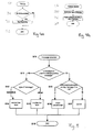
- step S1 The steps for starting the monitoring, i.e. for activating the listening unit 9 are shown in Figure 4a .
- the process starts in step S0 for example with switching on the electronic device 1.
- step S1 the electronic device 1 checks whether the monitoring is enabled by user settings. These settings can be input directly or via a remote device. In case that no monitoring is enabled then only this process ends in step S3. The normal operation of the electronic device 1 continues without the monitoring feature. Otherwise, if in step S2 it is detected that monitoring is enabled, then the monitoring via the listening unit 9 is started and this process then also ends in step S3 and in this case the normal operation of the electronic device 1 continues with the monitoring feature.
- FIG 4b shows the main steps according to the method of the present invention for monitoring messages.
- the process as shown in Figure 4b starts in step S4 with a detected message, i.e. the listening unit 9 has monitored a message transmitted within the network 8.
- the listening unit 9 transmits the monitored message to the processing unit 3, where it is further processed.
- the command or the message is handled according to the previously determined type, i.e. depending on the type of the message which has been monitored by the listening unit 9 the message is processed in a different way.
- the monitored message is output by the output means 2 in a specific way depending on the type of the message.
- This process ends in step S7. If another message is detected by the listening unit 9, this process will start again with step S4.
- Fig. 5 shows a first embodiment of the main process as explained with reference to Figs. 4a. and 4b.
- Fig. 5 shows the process in a general case but can also be adapted to networks where the communication bases on the CEC communication standard.
- On a CEC bus or generally speaking in any type of network there can be many polling messages to track for determining whether devices are present or not. Depending on the number of polling messages filtering can help to simplify the handling and to keep the overview.
- step S 10 This is achieved with the process as schematically shown in Fig. 5 .
- the process starts in step S 10 with the detection of a message by the listening unit 9.
- step S11 it is checked whether the monitored message is an unacknowledged polling message.
- a polling message within the CEC standard is hereby a sort of a ping. If this is the case it is further checked in step S13 if this polling message is the first unacknowledged polling message in a row. If this is also the case then on the output means which in this case may be a display a placeholder is inserted between the shown messages in step S16.
- step S13 it is determined that the unacknowledged polling message was not the first unacknowledged polling message in a row then in the next step S 17 this message is ignored and no further processing follows.
- step S 11 it is detected that the monitored message is not an unacknowledged polling message then in a further step S12 it is checked whether the message is a question or whether it is any other type of message. If it is a question then in the next step S 14 a normal line feed is provided on the output means 2 which in this case would be a display. Otherwise, if in step S12 it is determined that the message was not a question, then in the next step S 15 a double line feed is provided when outputting the messages monitored on the bus on the display. This process ends in step S 18. If another message is detected by the listening unit, this process will start again with step S10.
- neutral message is only exemplary for any type of neutral message, such as standby or the like.
- the user at once is able to have an overview of the messages as different types of messages are output in different ways.
- This approach is useful in a relaxed environment, i.e. an environment with low network traffic, where the answer of a question is normally received right after the questions.
- questions and corresponding answers are automatically grouped together on the display.
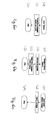
- Figures 6a, 6b, 6c and 7 show a second embodiment of the main process as explained with reference to Figures 4a and 4b .
- Figures 6a to 6c hereby show some process details of the process according to the second embodiment.
- the second embodiment hereby relates to the case, where numerous questions and answers are transmitted via the network 8.
- numerous questions and answers are transmitted via the network 8.
- several mechanisms and definitions are adopted, which are shown in Figures 6a to 6c .
- step S20 it is possible to define an error timeout, which means that the answer was not in time. For example it can be defined that an answer being later than 30s after the corresponding question is too late.
- an error timeout occurs then in the following step S21 an error message can be output indicating that the answer has not been received in time. The process ends in step S22.
- a question lifetime timeout can be defined, indicating that a question has not been answered, for example the question lifetime timeout can be set to one minute. If a question lifetime timeout occurs in step S23 then in step S24 the corresponding question is marked as not pending or is eleted and in the following step S25 an error message is output indicating that the answer is missing. The process ends in step S26. If in the later process the corresponding answer occurs very late then this answer is also marked as having no corresponding question due to the question lifetime timeout.
- a further possibility is to set an ignore mode for polling messages. That is after a first unacknowledged polling message has been detected, following polling messages in a row are ignored.
- polling messages in a row can refer to any type of polling messages in a row or can only refer to polling messages being addressed to the same address. For example if a first polling message is sent to the television and is not acknowledged, then the first polling message can be shown as unacknowledged and the following polling messages also sent to the television are ignored.
- An "ignore mode lifetime timeout" can be set in step.
- step S27 After a predefined time since the reception of the last unacknowledged polling message in a row the ignore mode can be cleared and from the on the first polling message which has not been acknowledged in a row is shown again. This is shown in Figure 6 . If the "Ignore mode lifetime timeout" is due in step S27, the ignore mode is cleared in step S28 and the process ends in step S29.
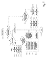
- FIG. 7 The whole process according to the second embodiment of the present invention is shown in Figure 7 .
- the processes of Figure 6a to 6c are either a part of the process of Figure 7 or run in parallel to Figure 7 .
- the process starts in step S30 with the detection of a message, i.e. the listening unit 9 monitors a message and submits the monitored message to the processing unit 3.
- next step S31 it is checked whether the detected message is an unacknowledged polling message.
- the message is an unacknowledged polling message
- in the following step S45 it is checked whether it is the first unacknowledged polling message in a row, i.e. whether it is the first unacknowledged polling messages in a row, e.g. the first unacknowledged polling message having the same addressee as a previous unacknowledged polling message, whereby in this case the ignore mode currently is not set.
- step S45 If in step S45 it is determined that it was the first unacknowledged polling message in a row then now the ignore mode is set in step S46 and it is further set an "ignore mode lifetime timeout" in step S47 indicating when the ignore mode showed is supposed to end and in step S48 a place holder is inserted in the lines on the display lines indicating that a first unacknowledged polling message in a row has occurred.
- step S45 if in step S45 it is detected that it was not the first unacknowledged polling message in a row and consequently the ignore mode is currently set, then in the following step S49 if the electronic device 1 is in the ignore mode then a new "ignore mode lifetime timeout" is set and in the following step S50 the unacknowledged polling messages during the ignore mode are not shown, i.e. are not output by the output means 2.
- step S32 the type of message is determined.
- the type of message can either be a question, an answer or any other message which in the following is denominated neutral message.
- a neutral message can for example be an acknowledged polling message or a CEC standby message.
- a neutral message is output in step S33 by the output means 2 either by outputting the content of the message, e.g. "standby sent from device A to device B" or with the indication "neutral message” or the like, e.g. indicated by colour or style.
- step S34 the question is marked as pending.
- step S35 the error timeout as previously explained is set and in the next step S36 the question lifetime timeout is also set as previously shown.
- step S37 the question is output by the output means 2, i.e. in the present embodiment shown on the display. In case the question lifetime timeout ends then the question will be marked as unanswered and an according error message will be output as explained with reference to Figure 6b .
- step S32 it is determined that the message was an answer, then in the next step S38 it is checked whether the corresponding question does still exist, i.e. whether the corresponding question was cancelled due to a question lifetime timeout or not. If the corresponding question does still exist, then in the following step S39 the question is marked as answered and the corresponding error timeout is deleted. In the next step S41 the answer is shown and linked to the corresponding question, as will be explained later. In case that in step S42 it is determined that the time since the question is exceeding the error timeout then additionally a warning is shown indicating that the answer is later than the error timeout or the answer is marked in a specific way.
- step S38 determines whether the corresponding question does exist then the process continues with step S43.
- the answer requires a corresponding question, then either the corresponding question was missing or has been cancelled due to a question lifetime timeout. In both cases the answer is shown without the question and together with an error message indicating that the question is missing. Otherwise the answer is shown without a question.
- CEC messages which are valid on their own and which do not necessarily require a corresponding question, e.g. if a new device into the network the new device will broadcast "report physical address", the same message is also the answer to the question "give physical address”.
- step S44 the corresponding answer together with eventual error messages is shown.
- the process in any case ends in step S51. If another message is detected by the listening unit 9, this process will start again with step S30.
- the question and answer can be marked depending on the time between question and answer. For example, if less than fifty seconds have passed between question and answer, then the question and answer pair is marked green, in case that the time between fifty seconds and a minute has elapsed, then the question and answer pair is marked yellow and otherwise in case that more than one minute has elapsed the question and answer pair is marked red.
- the process as explained with reference to Figure 7 is not limited to the described examples of marking the questions and answers.
- the question and answers can be marked by colouring the messages, by changing the size of the written commands on the display, by changing the position of the messages displayed by the output means 2, by formatting the question and answers in different ways, e.g. by underlining some messages or by writing some messages bold, or the like.
- an additional signal or message can be output by the output means in order to mark the question as unanswered or in order to mark the answer as having no question.
- step S31 can also be omitted and the corresponding following steps S45 to S50 can also be omitted.
- output by the output means 2 additional messages or indications thereby enabling a better overview of the output messages.
- debug messages can be output between the monitored messages in order to describe the general field the following messages are related to.
- the listening unit 9 will monitor the respective messages and the processing unit 3 will recognise those messages as belonging to a specific menu option or action accomplished by the user. Before outputting the monitored messages the output means 2 can then output an additional message indicating that the specific action or menu selection has been accomplished by the user and that therefore the following messages probably will belong to this action.
- the electronic device can be operated in different modes.
- the first mode is a passive mode, where only the listening unit 9 is activated and the electronic device listens to the traffic of the other devices within the network only.
- the other possibility is to provide the electronic device 1 in a normal CEC operation mode thereby showing all traffic including the own messages.
- the electronic device 1 is able to send via the output means 2 all kinds of CEC commands.
Priority Applications (2)
| Application Number | Priority Date | Filing Date | Title |
|---|---|---|---|
| EP08153758A EP2107721A1 (de) | 2008-03-31 | 2008-03-31 | Elektronische Vorrichtung und Verfahren zur Überwachung von Kommunikation in einem Netzwerk |
| US12/367,815 US8499070B2 (en) | 2008-03-31 | 2009-02-09 | Electronic device and method for monitoring communication within a network |
Applications Claiming Priority (1)
| Application Number | Priority Date | Filing Date | Title |
|---|---|---|---|
| EP08153758A EP2107721A1 (de) | 2008-03-31 | 2008-03-31 | Elektronische Vorrichtung und Verfahren zur Überwachung von Kommunikation in einem Netzwerk |
Publications (1)
| Publication Number | Publication Date |
|---|---|
| EP2107721A1 true EP2107721A1 (de) | 2009-10-07 |
Family
ID=39735167
Family Applications (1)
| Application Number | Title | Priority Date | Filing Date |
|---|---|---|---|
| EP08153758A Withdrawn EP2107721A1 (de) | 2008-03-31 | 2008-03-31 | Elektronische Vorrichtung und Verfahren zur Überwachung von Kommunikation in einem Netzwerk |
Country Status (2)
| Country | Link |
|---|---|
| US (1) | US8499070B2 (de) |
| EP (1) | EP2107721A1 (de) |
Families Citing this family (3)
| Publication number | Priority date | Publication date | Assignee | Title |
|---|---|---|---|---|
| US8938650B2 (en) * | 2011-02-28 | 2015-01-20 | Ricoh Company, Ltd. | Error report management |
| US9716743B2 (en) * | 2011-09-02 | 2017-07-25 | Microsoft Technology Licensing, Llc | Accessing hardware devices using web server abstractions |
| US11184308B2 (en) * | 2020-01-29 | 2021-11-23 | Dell Products L.P. | Configurable response tracking and monitoring of users who are responding to an email |
Citations (3)
| Publication number | Priority date | Publication date | Assignee | Title |
|---|---|---|---|---|
| WO2000028698A2 (en) * | 1998-11-09 | 2000-05-18 | Applied Digital Access | System and method of analyzing network protocols |
| US20040267924A1 (en) * | 2003-06-27 | 2004-12-30 | Fang Yang | System and method for monitoring network devices |
| EP1715629A1 (de) * | 2005-04-18 | 2006-10-25 | Peugeot Citroën Automobiles S.A. | System für die Anpassung eines Kommunikationsprotokolls mit einem in einem Fahrzeug untergebrachten Bordrechner |
Family Cites Families (14)
| Publication number | Priority date | Publication date | Assignee | Title |
|---|---|---|---|---|
| US4680753A (en) * | 1985-04-03 | 1987-07-14 | Texas Instruments Incorporated | System and method for controlling network bus communications for input-output interlocking information among distributed programmable controllers |
| US20050144240A1 (en) * | 2000-09-13 | 2005-06-30 | Janko Mrsic-Flogel | Data communications |
| US6839717B1 (en) * | 2001-10-15 | 2005-01-04 | Ricoh Company, Ltd. | Method and system of remote monitoring and support of devices, extracting data from different types of email messages, and storing data according to data structures determined by the message types |
| US7343407B2 (en) * | 2001-10-15 | 2008-03-11 | Ricoh Company, Ltd. | Method and system of remote monitoring and support of devices, including handling Email messages having message types specified within the Email message |
| US7154533B2 (en) * | 2001-10-30 | 2006-12-26 | Tandberg Telecom As | System and method for monitoring and diagnosis of video network performance |
| US20030084176A1 (en) * | 2001-10-30 | 2003-05-01 | Vtel Corporation | System and method for discovering devices in a video network |
| US20050138117A1 (en) * | 2003-12-18 | 2005-06-23 | Samsung Electronics Co., Ltd. | Method and system for pushing notifications to networked device |
| CA2463562A1 (en) * | 2004-04-07 | 2005-10-07 | Alcatel | Agent based router monitoring, diagnostic and maintenance |
| DE102004028534A1 (de) * | 2004-06-11 | 2006-01-05 | Christian Meentzen | Verfahren und Vorrichtung zur Überwachung des Verkehrs von elektronischen Nachrichten |
| US20060031476A1 (en) * | 2004-08-05 | 2006-02-09 | Mathes Marvin L | Apparatus and method for remotely monitoring a computer network |
| JP5249763B2 (ja) * | 2005-09-09 | 2013-07-31 | スミスズ ディテクション インコーポレイティド | 要求に応じたマルチメディアコンテンツのマルチキャスト配信 |
| RU2008108856A (ru) * | 2007-03-09 | 2009-09-20 | Май Холливуд Лтд. (Il) | Устройство, система и способ электронной связи с использованием аудиовизуальных клипов |
| KR101445637B1 (ko) * | 2007-06-14 | 2014-10-01 | 삼성전자주식회사 | Av 시스템에서 오디오 인터페이스를 체크하는 방법 및이를 이용한 장치 |
| US8307074B1 (en) * | 2010-07-15 | 2012-11-06 | Sprint Communications Company L.P. | Self-selected message queue monitoring |
-
2008
- 2008-03-31 EP EP08153758A patent/EP2107721A1/de not_active Withdrawn
-
2009
- 2009-02-09 US US12/367,815 patent/US8499070B2/en not_active Expired - Fee Related
Patent Citations (3)
| Publication number | Priority date | Publication date | Assignee | Title |
|---|---|---|---|---|
| WO2000028698A2 (en) * | 1998-11-09 | 2000-05-18 | Applied Digital Access | System and method of analyzing network protocols |
| US20040267924A1 (en) * | 2003-06-27 | 2004-12-30 | Fang Yang | System and method for monitoring network devices |
| EP1715629A1 (de) * | 2005-04-18 | 2006-10-25 | Peugeot Citroën Automobiles S.A. | System für die Anpassung eines Kommunikationsprotokolls mit einem in einem Fahrzeug untergebrachten Bordrechner |
Also Published As
| Publication number | Publication date |
|---|---|
| US20090248859A1 (en) | 2009-10-01 |
| US8499070B2 (en) | 2013-07-30 |
Similar Documents
| Publication | Publication Date | Title |
|---|---|---|
| JP4805990B2 (ja) | 移動通信端末機用モニタ装置及びモニタ制御方法 | |
| US7477880B2 (en) | Communication device, image-pickup device, storage medium and communication method | |
| JP5409220B2 (ja) | 電子機器及び電源制御方法 | |
| CN1717953B (zh) | 遥控器,遥控方法和被遥控设备 | |
| US8499070B2 (en) | Electronic device and method for monitoring communication within a network | |
| CN101715147A (zh) | 一种机顶盒性能测试方法、应用下载管理方法及设备 | |
| EP2261792A1 (de) | Bildschirmdatenübertragungssystem und die Erlangung von Benutzereinstellungen | |
| US20090049487A1 (en) | Router apparatus and network trouble determining method | |
| JP2011109604A (ja) | 電話受付システム、電話装置、通信装置及びコンピュータプログラム | |
| JP4482821B2 (ja) | 携帯端末、携帯端末診断方法および携帯端末診断プログラム | |
| CN110071744A (zh) | 蓝牙设备测试方法、装置及存储介质 | |
| US7650110B2 (en) | Wireless communication apparatus and wireless communication method for storing and accessing a plurality of images | |
| CN1452427A (zh) | 交互式电子设备 | |
| KR101642997B1 (ko) | 영상표시 시스템 및 이벤트 공유 방법 | |
| CN103259954A (zh) | 传真装置及其控制方法 | |
| CN108540687B (zh) | 信息处理系统以及图像形成装置 | |
| JP2003163950A (ja) | 故障診断システム、故障診断装置、コンピュータ及び故障診断方法 | |
| JP2007189435A (ja) | 監視装置 | |
| JP5509006B2 (ja) | 映像表示装置、映像再生装置、および携帯端末 | |
| JP2002305527A (ja) | 機器接続状態表示装置、並びに該装置における機器接続状態の表示方法 | |
| JP5271559B2 (ja) | 携帯型情報処理端末、情報家電装置、及び情報家電装置生した不具合の対処システム | |
| KR20080007748A (ko) | 감시용 카메라에서의 통신 선로 감시방법 | |
| CN117008546A (zh) | 设备数据的监测方法、装置、电子设备及存储介质 | |
| JPH1023234A (ja) | ファクシミリサーバ | |
| US20170244886A1 (en) | Imaging system and imaging terminal |
Legal Events
| Date | Code | Title | Description |
|---|---|---|---|
| PUAI | Public reference made under article 153(3) epc to a published international application that has entered the european phase |
Free format text: ORIGINAL CODE: 0009012 |
|
| AK | Designated contracting states |
Kind code of ref document: A1 Designated state(s): AT BE BG CH CY CZ DE DK EE ES FI FR GB GR HR HU IE IS IT LI LT LU LV MC MT NL NO PL PT RO SE SI SK TR |
|
| AX | Request for extension of the european patent |
Extension state: AL BA MK RS |
|
| AKX | Designation fees paid | ||
| STAA | Information on the status of an ep patent application or granted ep patent |
Free format text: STATUS: THE APPLICATION IS DEEMED TO BE WITHDRAWN |
|
| 18D | Application deemed to be withdrawn |
Effective date: 20100408 |
|
| REG | Reference to a national code |
Ref country code: DE Ref legal event code: 8566 |