EP0200114B1 - Auslegevorrichtung - Google Patents
Auslegevorrichtung Download PDFInfo
- Publication number
- EP0200114B1 EP0200114B1 EP86105384A EP86105384A EP0200114B1 EP 0200114 B1 EP0200114 B1 EP 0200114B1 EP 86105384 A EP86105384 A EP 86105384A EP 86105384 A EP86105384 A EP 86105384A EP 0200114 B1 EP0200114 B1 EP 0200114B1
- Authority
- EP
- European Patent Office
- Prior art keywords
- delivery device
- conveying
- delivery
- band
- rib
- Prior art date
- Legal status (The legal status is an assumption and is not a legal conclusion. Google has not performed a legal analysis and makes no representation as to the accuracy of the status listed.)
- Expired
Links
- 238000011161 development Methods 0.000 description 4
- 230000018109 developmental process Effects 0.000 description 4
- 238000010276 construction Methods 0.000 description 2
- 230000009286 beneficial effect Effects 0.000 description 1
- 238000000576 coating method Methods 0.000 description 1
- 230000003247 decreasing effect Effects 0.000 description 1
- 239000000463 material Substances 0.000 description 1
- 239000002184 metal Substances 0.000 description 1
- 230000008092 positive effect Effects 0.000 description 1
Images
Classifications
-
- B—PERFORMING OPERATIONS; TRANSPORTING
- B65—CONVEYING; PACKING; STORING; HANDLING THIN OR FILAMENTARY MATERIAL
- B65H—HANDLING THIN OR FILAMENTARY MATERIAL, e.g. SHEETS, WEBS, CABLES
- B65H29/00—Delivering or advancing articles from machines; Advancing articles to or into piles
- B65H29/66—Advancing articles in overlapping streams
-
- B—PERFORMING OPERATIONS; TRANSPORTING
- B65—CONVEYING; PACKING; STORING; HANDLING THIN OR FILAMENTARY MATERIAL
- B65H—HANDLING THIN OR FILAMENTARY MATERIAL, e.g. SHEETS, WEBS, CABLES
- B65H29/00—Delivering or advancing articles from machines; Advancing articles to or into piles
- B65H29/38—Delivering or advancing articles from machines; Advancing articles to or into piles by movable piling or advancing arms, frames, plates, or like members with which the articles are maintained in face contact
- B65H29/40—Members rotated about an axis perpendicular to direction of article movement, e.g. star-wheels formed by S-shaped members
Definitions
- the invention relates to a delivery device with at least one transport path that defines a transport plane that engages under a paddle wheel and that receives the products deposited on it by the paddle wheel, in particular in the form of a shingled stream.
- At least one web is provided which is aligned in the delivery direction, is raised in relation to the transport plane on the transport plane, has a sloping in the delivery direction and enters the front end into the transport band-side transport plane.
- the products leaving the paddle wheel initially come to rest on the narrow edge of the web on the impeller side, and in doing so practically receive a bend running in the direction of delivery, which stabilizes the products and ensures exact guidance of the products along the web running in the direction of delivery.
- a so-called floating of the products i. H. a sliding of the products on an air cushion prevented, so that an exact positioning of the products is achieved not only transversely to the direction of delivery, but also in the direction of delivery.
- a bridge arranged in the middle can be provided. This practically results in a strong central beading of the products and therefore, despite little effort, particularly precise positioning.
- Another useful measure can be that the inclination of the top edge of the web is adjustable. This measure enables an exact adjustment of the position of the upper web edge to the respective product length or product thickness.
- a particularly advantageous embodiment of the superordinate measures can consist in the fact that the central region of the web at least touches the outer circumference of the impeller, preferably engages in the outer circumference of the impeller. This measure ensures that the web is already in action while the products are still in the paddle wheel. The products are practically pressed against the web by the blades adjacent to the web, which ensures high accuracy both in the direction of delivery and transversely to it.
- the web can be designed as an upper run of a preferably driven belt belt that is deflected from the rear to the front relative to the transport plane on the transport plane. This results in no or only negligibly small relative movements between the products and the upper run of the belt which forms the web, which ensures particularly gentle treatment of the products.
- these measures enable a particularly simple and maintenance-friendly outlay, since no sliding coatings, etc. are required, and since, due to the lack of relative movement of the products relative to the web, low-wear operation is also guaranteed.
- a further expedient measure can consist in that the belt belt is driven with a surface speed that is about 1% to 5% lower than the conveyor belt or the conveyor belts, which experience has shown can have a positive effect on the securing and exact positioning of the products.
- the belt belt can be flanked by at least two conveyor belts, the conveyor belts and the belt belt being around a common front drive roller, preferably provided with a puncture assigned to the belt belt, is guided around and the belt belt is assigned a rear deflection roller which is independent of the rear deflection members assigned to the conveyor belts and whose diameter is larger than the diameter of the drive roller.
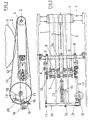
- the delivery device on which the figures are based consists of conveyor belts 2 running in the delivery direction and passing a distance below a paddle wheel 1.
- these are two comparatively wide flat conveyor belts arranged next to one another with a small mean distance which are arranged at least on the upper run side in a plane and whose surface facing the paddle wheel 1 accordingly defines a transport plane.
- the conveyor belts 2 are unguided by front and rear deflection elements in the direction of delivery.
- a deflecting roller 4 is provided which is continuous over the machine width and is coupled to a drive shaft 3.
- deflection drums 6 which are freely rotatably mounted are provided on an axis 5 which is continuous over the width of both conveyor belts 2.
- the effective diameter of the driven, front deflection roller 4 and the rear deflection drums 6 is approximately the same, so that the lower run of the conveyor belts runs parallel to the assigned upper run.
- the front deflecting roller 4 is rotatably mounted on the frame side walls 7 via the drive shaft 3 and a bearing pin opposite this.
- the axis 5 assigned to the rear deflection drums 6 engages with lateral flat pins in slots in lateral bearing straps 8 which are clamped onto a cross member 9 fastened to the frame side walls 7.
- the distance of the transport plane defined by the conveyor belts 2 from the circumference of the paddle wheel can be adjusted by rotating the bearing straps 8 relative to the crossmember 9.
- the flat pins of the axis 5 receiving the rear deflection drums 6 are supported by setscrews 10 on the bearing straps 8.
- the axis 5 is supported not only on the lateral bearing brackets 8 but also on a central bearing bracket 8a, which is also clamped onto the crossbeam 9, in order to avoid excessive deflection.
- a web 11 which is arranged in the center and extends in the direction of delivery, raised compared to the transport plane defined by the conveyor belts 2, the upper web edge of which falls from the rear in the delivery direction and runs into the transport plane at its front end , as Figure 1 clearly shows.
- a web 11 arranged in the middle is provided.
- the upper edge of the web 11 on the impeller side has a straight, linearly descending course.
- the folded products to be deposited by the paddle wheel 1 onto the conveyor belts 2 in the form of a scale track are kinked or corrugated by the web 11 which is raised compared to the conveyor belts 2 and thus stabilized with regard to their position.
- the decreasing height distance in the cantilever direction from the upper edge of the web 11 having the transport plane 2 defined by the transport belts 2 can run past the paddle wheel 1 at a short distance, in any case less than the transport belts 2, or can affect the paddle wheel 1.
- the web 11 engages with its upper edge in the impeller, i. H. between two disks of the impeller 1 formed by blades, so that the products to be deposited by the impeller are pressed against the web 11.
- the increasing backward height of the top edge of the web, i.e. H. the inclination with respect to the transport level can be adjusted so that gentle handling of the products can be achieved even when processing different products.
- the web 11 can be designed as a fixed tongue provided with a sliding support, for example in the form of a sheet metal strip or pipe bracket.
- the web 11 is formed by the upper run of a narrow, tensioned belt band 12 which runs from the rear to the front and is guided over two deflection members.
- the belt band 12 can be designed as a narrow flat belt, as a V-belt or as a rope or the like. In any case, there is a web 11 with an elastically resilient upper edge, which can be very beneficial for the protection of the products.
- the belt band 12 is designed as a circulating belt, so that relative movements between the products and the web forming the upper run of the belt band 12 are largely eliminated.
- the belt band 12 forming the web 11 is provided with a positive drive, so that a continuous movement and thus a particularly nice operation can be guaranteed.
- the belt belt 12 forming the web 11 is driven here with a surface speed lying about 1% to 5% below the surface speed of the conveyor belts 2, which experience has shown ensures that the products are positioned particularly precisely on the conveyor belts 2.
- the belt belt 12 is in the illustrated embodiment in the area of the front, in the transport plane of the conveyor belts 2 cutting end around the continuous conveyor roller 4 assigned to the two conveyor belts 2, so that there is a clean entry of the web edge into the belt-side transport plane and an automatic Drive the belt band 12 forming the web 11 result.
- the deflection roller 4 can simply be provided with an entry assigned to the belt band 12.
- the belt band 12 is guided around a deflection roller 13 which is independent of the deflection drum 6 assigned to the conveyor belts 2 and whose diameter is so much larger than the diameter of the front deflection roller 4 and which is arranged such that the desired one is from behind forward sloping course of the upper run forming the web 11 of the belt band 12 results in that, at the same time, even in the case of a height adjustment of the deflection roller 13, collisions of the lower run of the belt band 12 with components that are continuous over the machine width, such as, for example, the traverse 9 or the axis 5, are avoided.
- the deflection roller 13 has approximately twice the diameter of the front deflection roller 4 or the deflection drum 6.
- the height arrangement of the deflection roller 13 is chosen such that, in a central position, both the upper run running from its circumference and that running up to its circumference
- the lower run of the belt band 12 runs out from the plane of the upper or lower run of the conveyor belts 2 with increasing distance from the front to the rear, which allows the inclination of the upper run of the belt band 12 forming the web 11 to be freely adjusted.
- the deflection roller 13 is arranged in the area behind the rear deflection drum 6 assigned to the conveyor belts 2, which results in good accessibility of the deflection roller 13 and thus a simple structure and a comparatively large web length.
- the deflection roller 13 is freely rotatably mounted on an axis 14 parallel to the axis 5 receiving the rear deflection drum 6 of the conveyor belts 2 and is fastened on a holder 15 which can be pivoted about an axis parallel to the axis.
- the holder 15 is designed as a lug-shaped swivel arm which is clamped onto a rod 16, the ends of which are rotatably mounted with their ends in extensions of the bearing brackets 8 which project beyond the axis 5 and can be pivoted by means of a clamped-on actuating arm 18 .
- an adjusting spindle 20 is provided which is threadedly engaged with a pin 19 which is rotatably received on the swivel arm 18 and which can be actuated by means of a handwheel and which is supported on a bearing block 21 fastened to the adjacent holding bracket.
- the rod 16 By rotating the adjusting spindle 20, the rod 16 can be pivoted and the axis 14 receiving the deflection roller 13 can be raised more or less.
- the resultant change in the length of the belt band 12 lies in the elastic range of the band material.
- the pitch of the thread of the threaded spindle 20 can be chosen so that self-locking is ensured. However, it would also be conceivable to provide a locking pin etc. assigned to the threaded spindle (20) to secure the set web position.
Landscapes
- Engineering & Computer Science (AREA)
- Mechanical Engineering (AREA)
- Structure Of Belt Conveyors (AREA)
- Separation, Sorting, Adjustment, Or Bending Of Sheets To Be Conveyed (AREA)
- Feeding Of Articles By Means Other Than Belts Or Rollers (AREA)
- Discharge By Other Means (AREA)
Applications Claiming Priority (2)
| Application Number | Priority Date | Filing Date | Title |
|---|---|---|---|
| DE19853515328 DE3515328A1 (de) | 1985-04-27 | 1985-04-27 | Auslegevorrichtung |
| DE3515328 | 1985-04-27 |
Publications (2)
| Publication Number | Publication Date |
|---|---|
| EP0200114A1 EP0200114A1 (de) | 1986-11-05 |
| EP0200114B1 true EP0200114B1 (de) | 1988-07-06 |
Family
ID=6269338
Family Applications (1)
| Application Number | Title | Priority Date | Filing Date |
|---|---|---|---|
| EP86105384A Expired EP0200114B1 (de) | 1985-04-27 | 1986-04-18 | Auslegevorrichtung |
Country Status (4)
| Country | Link |
|---|---|
| US (1) | US4690396A (https=) |
| EP (1) | EP0200114B1 (https=) |
| JP (1) | JPH0694326B2 (https=) |
| DE (2) | DE3515328A1 (https=) |
Families Citing this family (2)
| Publication number | Priority date | Publication date | Assignee | Title |
|---|---|---|---|---|
| US4802578A (en) * | 1985-09-05 | 1989-02-07 | Vsesojuzny Nauchno-Issledovatelsky I Ispytatelny Institut Meditsinskoi Tekhniki | Surgical instrument |
| DD264190A1 (de) * | 1987-09-04 | 1989-01-25 | Polygraph Leipzig | Schaufelradausleger zur schuppenauslage von druckprodukten |
Family Cites Families (7)
| Publication number | Priority date | Publication date | Assignee | Title |
|---|---|---|---|---|
| US1325550A (en) * | 1919-12-23 | Ginia | ||
| US953045A (en) * | 1908-07-03 | 1910-03-29 | Hoe & Co R | Sheet-delivery mechanism. |
| US3847384A (en) * | 1973-01-30 | 1974-11-12 | Smithe Machine Co Inc F L | Apparatus for collating sheet like elements |
| SE413007B (sv) * | 1977-04-12 | 1980-03-31 | Wifag Maschf | Anordning for att bilda en strom av overlappade falsade tryckprodukter |
| DE3153613C2 (https=) * | 1980-09-16 | 1992-06-17 | Ferag Ag, Hinwil, Zuerich, Ch | |
| DE3108681A1 (de) * | 1981-03-07 | 1982-09-30 | M.A.N.- Roland Druckmaschinen AG, 6050 Offenbach | "einrichtung zur entnahme von druckexemplaren aus den schaufelraedern eines falzapparates" |
| DE3123406C2 (de) * | 1981-06-12 | 1985-12-12 | Albert-Frankenthal Ag, 6710 Frankenthal | Vorrichtung zur Produktausrichtung |
-
1985
- 1985-04-27 DE DE19853515328 patent/DE3515328A1/de active Granted
-
1986
- 1986-04-14 US US06/851,801 patent/US4690396A/en not_active Expired - Lifetime
- 1986-04-18 DE DE8686105384T patent/DE3660359D1/de not_active Expired
- 1986-04-18 EP EP86105384A patent/EP0200114B1/de not_active Expired
- 1986-04-25 JP JP61097821A patent/JPH0694326B2/ja not_active Expired - Lifetime
Also Published As
| Publication number | Publication date |
|---|---|
| JPH0694326B2 (ja) | 1994-11-24 |
| DE3515328A1 (de) | 1986-10-30 |
| JPS61254461A (ja) | 1986-11-12 |
| EP0200114A1 (de) | 1986-11-05 |
| US4690396A (en) | 1987-09-01 |
| DE3515328C2 (https=) | 1987-04-02 |
| DE3660359D1 (en) | 1988-08-11 |
Similar Documents
| Publication | Publication Date | Title |
|---|---|---|
| DE3720169C2 (https=) | ||
| WO1994014692A1 (de) | Vorrichtung zum ablegen von produkten | |
| EP3372719A1 (de) | Vliesbahn-führungsvorrichtung | |
| DE2242993C3 (de) | Transportriementrieb | |
| DD159419A1 (de) | Tisch zum foerdern und seitlichen ausrichten von papierbogen | |
| DE19541095C2 (de) | Verfahren zur Förderung eines Bandes aus plastischem Material und Fördertisch zur kontinuierlichen Förderung von bandförmigem plastischem Material | |
| EP0200114B1 (de) | Auslegevorrichtung | |
| DE2415003A1 (de) | Fotoelektrische zaehlvorrichtung fuer papierfoerderer | |
| DE3212350C2 (de) | Vorrichtung zum Auseinanderziehen von ineinandersteckenden Bogen | |
| DE3732419C1 (de) | Rundstapelbogenanleger | |
| EP0625121A1 (de) | Einrichtung zum hüberführen eines aus druckprodukten gebildeten schuppenstroms | |
| DE3703845A1 (de) | Vorrichtung zum vereinzeln gestapelter zuschnitte | |
| DE3840647C2 (de) | Vorrichtung zum Weiterfördern von Druckprodukten | |
| CH703679B1 (de) | Umlenkvorrichtung für Transportband. | |
| DE3313196C1 (de) | Vorrichtung zum Spannen eines bandförmigen Förderorganes | |
| DE2917666C2 (de) | Schärmaschine | |
| EP0214458B1 (de) | Vorrichtung zur Vereinigung von zwei nebeneinanderlaufenden Schuppenströmen | |
| DE19960347C2 (de) | Vorrichtung zum Ablenken eines Schuppenstroms auf einem Rolltisch | |
| DE29520112U1 (de) | Vorrichtung zum Trennen und seitlichem Auslenken durch Längsschnitt erzeugten Metallstreifen | |
| AT403132B (de) | Richttisch zum ausrichten und positionieren von schnitthölzern bezüglich einer holzbearbeitungsmaschine | |
| DE3316284A1 (de) | Vorrichtung zum aufrechterhalten einer bestimmten lage eines angeflachten holzes beim transport zwischen arbeitsstationen | |
| EP0248347A1 (de) | Falzapparat | |
| DE3616801C1 (de) | Gurtbecherwerk fuer Senkrechtfoerderer | |
| DE3827108A1 (de) | Abstapler | |
| DE9002551U1 (de) | Furnier-Einzugsvorrichtung |
Legal Events
| Date | Code | Title | Description |
|---|---|---|---|
| PUAI | Public reference made under article 153(3) epc to a published international application that has entered the european phase |
Free format text: ORIGINAL CODE: 0009012 |
|
| AK | Designated contracting states |
Kind code of ref document: A1 Designated state(s): CH DE FR GB IT LI |
|
| 17P | Request for examination filed |
Effective date: 19870324 |
|
| 17Q | First examination report despatched |
Effective date: 19871026 |
|
| GRAA | (expected) grant |
Free format text: ORIGINAL CODE: 0009210 |
|
| AK | Designated contracting states |
Kind code of ref document: B1 Designated state(s): CH DE FR GB IT LI |
|
| ITF | It: translation for a ep patent filed | ||
| GBT | Gb: translation of ep patent filed (gb section 77(6)(a)/1977) | ||
| REF | Corresponds to: |
Ref document number: 3660359 Country of ref document: DE Date of ref document: 19880811 |
|
| ET | Fr: translation filed | ||
| PLBE | No opposition filed within time limit |
Free format text: ORIGINAL CODE: 0009261 |
|
| STAA | Information on the status of an ep patent application or granted ep patent |
Free format text: STATUS: NO OPPOSITION FILED WITHIN TIME LIMIT |
|
| 26N | No opposition filed | ||
| ITTA | It: last paid annual fee | ||
| PGFP | Annual fee paid to national office [announced via postgrant information from national office to epo] |
Ref country code: FR Payment date: 20010420 Year of fee payment: 16 |
|
| PGFP | Annual fee paid to national office [announced via postgrant information from national office to epo] |
Ref country code: GB Payment date: 20010425 Year of fee payment: 16 |
|
| PGFP | Annual fee paid to national office [announced via postgrant information from national office to epo] |
Ref country code: CH Payment date: 20010504 Year of fee payment: 16 |
|
| PGFP | Annual fee paid to national office [announced via postgrant information from national office to epo] |
Ref country code: DE Payment date: 20010628 Year of fee payment: 16 |
|
| REG | Reference to a national code |
Ref country code: GB Ref legal event code: IF02 |
|
| PG25 | Lapsed in a contracting state [announced via postgrant information from national office to epo] |
Ref country code: GB Free format text: LAPSE BECAUSE OF NON-PAYMENT OF DUE FEES Effective date: 20020418 |
|
| PG25 | Lapsed in a contracting state [announced via postgrant information from national office to epo] |
Ref country code: LI Free format text: LAPSE BECAUSE OF NON-PAYMENT OF DUE FEES Effective date: 20020430 Ref country code: CH Free format text: LAPSE BECAUSE OF NON-PAYMENT OF DUE FEES Effective date: 20020430 |
|
| PG25 | Lapsed in a contracting state [announced via postgrant information from national office to epo] |
Ref country code: DE Free format text: LAPSE BECAUSE OF NON-PAYMENT OF DUE FEES Effective date: 20021101 |
|
| GBPC | Gb: european patent ceased through non-payment of renewal fee |
Effective date: 20020418 |
|
| REG | Reference to a national code |
Ref country code: CH Ref legal event code: PL |
|
| PG25 | Lapsed in a contracting state [announced via postgrant information from national office to epo] |
Ref country code: FR Free format text: LAPSE BECAUSE OF NON-PAYMENT OF DUE FEES Effective date: 20021231 |
|
| REG | Reference to a national code |
Ref country code: FR Ref legal event code: ST |
|
| PG25 | Lapsed in a contracting state [announced via postgrant information from national office to epo] |
Ref country code: IT Free format text: LAPSE BECAUSE OF NON-PAYMENT OF DUE FEES;WARNING: LAPSES OF ITALIAN PATENTS WITH EFFECTIVE DATE BEFORE 2007 MAY HAVE OCCURRED AT ANY TIME BEFORE 2007. THE CORRECT EFFECTIVE DATE MAY BE DIFFERENT FROM THE ONE RECORDED. Effective date: 20050418 |