EP0199098B1 - Cross-country ski binding - Google Patents
Cross-country ski binding Download PDFInfo
- Publication number
- EP0199098B1 EP0199098B1 EP86103810A EP86103810A EP0199098B1 EP 0199098 B1 EP0199098 B1 EP 0199098B1 EP 86103810 A EP86103810 A EP 86103810A EP 86103810 A EP86103810 A EP 86103810A EP 0199098 B1 EP0199098 B1 EP 0199098B1
- Authority
- EP
- European Patent Office
- Prior art keywords
- ski
- joint
- arms
- cross
- ski boot
- Prior art date
- Legal status (The legal status is an assumption and is not a legal conclusion. Google has not performed a legal analysis and makes no representation as to the accuracy of the status listed.)
- Expired - Lifetime
Links
Images


Classifications
-
- A—HUMAN NECESSITIES
- A63—SPORTS; GAMES; AMUSEMENTS
- A63C—SKATES; SKIS; ROLLER SKATES; DESIGN OR LAYOUT OF COURTS, RINKS OR THE LIKE
- A63C9/00—Ski bindings
- A63C9/08—Ski bindings yieldable or self-releasing in the event of an accident, i.e. safety bindings
- A63C9/086—Ski bindings yieldable or self-releasing in the event of an accident, i.e. safety bindings using parts which are fixed on the shoe of the user and are releasable from the ski binding
-
- A—HUMAN NECESSITIES
- A63—SPORTS; GAMES; AMUSEMENTS
- A63C—SKATES; SKIS; ROLLER SKATES; DESIGN OR LAYOUT OF COURTS, RINKS OR THE LIKE
- A63C9/00—Ski bindings
- A63C9/006—Ski bindings with a climbing wedge
-
- A—HUMAN NECESSITIES
- A63—SPORTS; GAMES; AMUSEMENTS
- A63C—SKATES; SKIS; ROLLER SKATES; DESIGN OR LAYOUT OF COURTS, RINKS OR THE LIKE
- A63C9/00—Ski bindings
- A63C9/08—Ski bindings yieldable or self-releasing in the event of an accident, i.e. safety bindings
- A63C9/0807—Ski bindings yieldable or self-releasing in the event of an accident, i.e. safety bindings for both towing and downhill skiing
-
- A—HUMAN NECESSITIES
- A63—SPORTS; GAMES; AMUSEMENTS
- A63C—SKATES; SKIS; ROLLER SKATES; DESIGN OR LAYOUT OF COURTS, RINKS OR THE LIKE
- A63C9/00—Ski bindings
- A63C9/08—Ski bindings yieldable or self-releasing in the event of an accident, i.e. safety bindings
- A63C9/084—Ski bindings yieldable or self-releasing in the event of an accident, i.e. safety bindings with heel hold-downs, e.g. swingable
- A63C9/0845—Ski bindings yieldable or self-releasing in the event of an accident, i.e. safety bindings with heel hold-downs, e.g. swingable the body or base or a jaw pivoting about a vertical axis, i.e. side release
-
- A—HUMAN NECESSITIES
- A63—SPORTS; GAMES; AMUSEMENTS
- A63C—SKATES; SKIS; ROLLER SKATES; DESIGN OR LAYOUT OF COURTS, RINKS OR THE LIKE
- A63C9/00—Ski bindings
- A63C9/08—Ski bindings yieldable or self-releasing in the event of an accident, i.e. safety bindings
- A63C9/085—Ski bindings yieldable or self-releasing in the event of an accident, i.e. safety bindings with sole hold-downs, e.g. swingable
- A63C9/08507—Ski bindings yieldable or self-releasing in the event of an accident, i.e. safety bindings with sole hold-downs, e.g. swingable with a plurality of mobile jaws
- A63C9/08528—Ski bindings yieldable or self-releasing in the event of an accident, i.e. safety bindings with sole hold-downs, e.g. swingable with a plurality of mobile jaws pivoting about a longitudinal axis
-
- A—HUMAN NECESSITIES
- A63—SPORTS; GAMES; AMUSEMENTS
- A63C—SKATES; SKIS; ROLLER SKATES; DESIGN OR LAYOUT OF COURTS, RINKS OR THE LIKE
- A63C9/00—Ski bindings
- A63C9/20—Non-self-releasing bindings with special sole edge holders instead of toe-straps
Description
Die Erfindung betrifft eine Tourenskibindung, bestehend aus einer vorderen Halterung zur schwenkbaren Lagerung eines Skischuhes beim Tourengehen, wobei die vordere Halterung zwei schwenkbar gelagerte und-einander gegenüberliegende Spannteile aufweist, die dazu bestimmt sind, in der Betriebsstellung gegen korrespondierende, an den Seiten des Skischuhes angeordnete Ausnehmungen bzw. Vorsprünge gedrückt zu werden, und aus einem Hinterbacken zur Fixierung des Skischuhes bei Abfahrten bzw. zum Abstützen des Fersenteiles des Skischuhes bei Anstiegen.The invention relates to a touring ski binding, consisting of a front bracket for the pivotable mounting of a ski boot when touring, the front bracket having two pivotally mounted and-opposing clamping parts, which are intended in the operating position against corresponding, arranged on the sides of the ski shoe Recesses or projections to be pressed, and from a buttock to fix the ski boot on descents or to support the heel part of the ski boot on climbs.
Bei einer bekannten Anordnung zum Tourenskifahren (AT-PS 376 577) sind im Bereich der Schuhspitze eines Skischuhes annähernd horizontal und quer zur Schuhlängsrichtung über beide seitlichen Begrenzungen der Schuhsohle vorstehende Bolzen vorgesehen. An der Skibindung sind verstellbare, jedoch fixierbare Hebelarme angeordnet, deren freie Enden mit den am Skischuh vorstehenden Bolzen zur Bildung einer feststehenden Drehachse in Wirkverbindung bringbar sind. Die beiden Hebelarme liegen an den Längsrändern eines klotzartigen, feststehenden Bindungsteiles an, wobei die freien, mit dem Bolzen am Skischuh in Wirkverbindung bringbaren Enden der Hebelarme den feststehenden Bindungsteil skischuhseitig überragen. Diese Anordnung hat sich voll bewährt, ist jedoch in konstruktiver Hinsicht noch verbesserungsfähig insbesondere im Hinblick auf die Stabilität und die Funktionstüchtigkeit, da beispielsweise in der Anordnung gemäß dieser bekannten Ausführung die Gefahr gegeben ist, daß Schnee zwischen die sich bewegenden Teile hineingelangt, was die Funktionstüchtigkeit stören kann.In a known arrangement for touring skiing (AT-PS 376 577), bolts protruding approximately horizontally and transversely to the longitudinal direction of the shoe over both lateral boundaries of the sole of the shoe are provided in the area of the toe of a ski shoe. Adjustable but fixable lever arms are arranged on the ski binding, the free ends of which can be brought into operative connection with the bolts projecting from the ski boot to form a fixed axis of rotation. The two lever arms rest against the longitudinal edges of a block-like, fixed binding part, the free ends of the lever arms which can be brought into operative connection with the bolt on the ski boot projecting beyond the fixed binding part on the ski boot side. This arrangement has proven itself fully, but can still be improved from a constructional point of view, in particular with regard to stability and functionality, since, for example, in the arrangement according to this known embodiment there is a risk that snow will get between the moving parts, which is the functionality can disturb.
Es ist ferner eine Skibindung bekannt (AT-PS 315 042), bei der unterhalb der Schuhsohle und in einer parallel zur Skioberseite gelegenen Ebene entgegen einer Federkraft verschwenkbar gelagerte Hebel angeordnet sind, die Niederhalter aufweisen, welchen an beiden Seiten des Skischuhes vorgesehene Widerlager zugeordnet werden. Zum Tourengehen übergreifen die Niederhalter einen nahe der Schuhspitze angeordneten Bolzen. Es kann dann der Skischuh, wie beim Tourengehen erforderlich, hochgeschwenkt werden. Es ist damit möglich, diese Einrichtung sowohl für die Abfahrt als auch zum Tourengehen zu verwenden. Als besonders nachteilig stellt sich aber heraus, daß beim Tourengehen der Skischuh, bezogen auf die Skilänge, ein entsprechend großes Stück gegen das Skiende hin versetzt befestigt ist, so daß die Gewichtsverteilung zwischen Schuh und Ski kaum mehr stimmt. Die Art der Anordnung und der Betätigung der Hebel ist aufwendig und daher teuer. Es müssen komplette Zuggestänge und Spannglieder vorgesehen werden.A ski binding is also known (AT-PS 315 042), in which levers are arranged below the sole of the shoe and in a plane parallel to the upper side of the ski which can be pivoted against a spring force and which have hold-down devices to which abutments provided on both sides of the ski shoe are assigned . For touring, the hold-downs overlap a bolt located near the tip of the shoe. The ski boot can then be swiveled up as required when touring. It is therefore possible to use this device for both downhill and touring. It turns out to be particularly disadvantageous that when touring the ski boot, relative to the length of the ski, a correspondingly large piece is attached offset towards the end of the ski, so that the weight distribution between the boot and the ski is hardly correct. The type of arrangement and actuation of the levers is complex and therefore expensive. Complete tension rods and tendons must be provided.
Bei einer bekannten Langlauf-Sicherheitsskibindung (DE-A 2 907 359) sind zwei schwenkbar gelagerte und einander gegenüber liegende Spannteile vorgesehen, welche gegen korrespondierende, an den Seiten des Langlaufschuhes angeordnete Ausnehmungen gedrückt werden können. Diese beiden Spannteile sind an Winkelhebeln angeordnet, welche um rechtwinklig von der Skioberfläche abstehende Bolzen verschwenkbar sind und außerdem über eine Art Verzahnung in ihrer Verschwenkebene miteinander in Wirkverbindung stehen. Zum Einrasten dieser Spannteile muß der Benützer den - Langiaufschuh exakt auf die Höhe der Spannteile bringen, worauf dann durch Niederdrücken eines an den anderen Armen dieser Hebel angeordneten Betätigungsteiles die Spannteile gegen den Langlaufschuh verschwenkt werden und dann in die Ausnehmungen am Langlaufschuh eingreifen. Es ist auf jeden Fall eine zusätzliche manuelle Betätigung erforderlich, um ein Einrasten der Langlauf-Skibindung zu bewirken.In a known cross-country safety ski binding (DE-A 2 907 359), two pivoting and opposing clamping parts are provided, which can be pressed against corresponding recesses arranged on the sides of the cross-country boot. These two clamping parts are arranged on angle levers which can be pivoted about bolts protruding at right angles from the ski surface and are also operatively connected to one another via a type of toothing in their pivoting plane. To engage these clamping parts, the user must bring the - Langiufschuh exactly to the height of the clamping parts, whereupon the clamping parts are pivoted against the cross-country shoe by depressing an actuating part arranged on the other arms of these levers and then engage in the recesses on the cross-country shoe. In any case, additional manual actuation is required to lock the cross-country ski binding into place.
Bei einer weiteren bekannten Anordnung (US-A 4 348 036) ist ebenfalls eine Langlauf-Skibindung so konstruiert, daß um zur Skioberfläche rechtwinklig abstehende Bolzen Hebel verschwenkbar gehalten sind, welche an ihrem einen Ende die Spannteile aufweisen, welche in Ausnehmungen am vorderen Ende des Langlaufskischuhs eingreifen können, und an ihrem anderen Arm miteinander über Bolzen und Langlöcher in Wirkverbindung stehen. Ein Eindrücken des Langlaufschuhes in diese Bindung wäre wohl in Längsrichtung des Skis denkbar, wobei aber zu diesem Einschwenken die Kraft einer Feder überwunden werden muß. Damit es überhaupt zu einem Einrasten kommen kann, muß der Langlaufschuh exakt in der Mittelachse zwischen den beiden Spannteilen eingeschoben werden, da ein ordnungsgemäßes Einführen praktisch nur dann möglich ist, wenn beide Hebel gleichzeitig ausgeschwenkt werden.In a further known arrangement (US-A 4 348 036), a cross-country ski binding is also constructed so that levers are held pivotably about bolts which protrude at right angles to the ski surface and which have the clamping parts at one end, which have recesses at the front end of the Cross-country ski boots can intervene, and are operatively connected to each other on their other arm via bolts and elongated holes. Pressing the cross-country ski boot into this binding would be conceivable in the longitudinal direction of the ski, but the force of a spring must be overcome for this pivoting. So that it can even snap into place, the cross-country shoe must be inserted exactly in the central axis between the two clamping parts, since proper insertion is practically only possible if both levers are swung out at the same time.
Bei den meisten derzeit gebräuchlichen Tourenskibindungen (z.B. AT-PS 309 292) sind Vorder-und Hinterbacken durch eine Platte oder einen Rahmen miteinander verbunden. Der Skischuh wird mittels der Backen und Fersenstrammern auf diese Platte gespannt. Um die für das Gehen notwendige Fersenfreiheit zu erreichen, besitzt die Platte vorne ein scharnierartiges Gelenk zur Verbindung mit einem auf dem Ski angeordneten Bindungsteil. Für die Abfahrt kann die Platte im Fersenbereich durch eine Verriegelungsvorrichtung an einem skifesten Bindungsteil fixiert werden. Es ist hier immer eine zusätzliche, auf den Skischuh abzustimmende Sohlenplatte erforderlich.In most of the touring ski bindings currently in use (e.g. AT-PS 309 292), the front and rear cheeks are connected to each other by a plate or a frame. The ski boot is stretched onto this plate using the cheeks and heel straps. In order to achieve the heel clearance required for walking, the plate has a hinge-like joint at the front for connection to a binding part arranged on the ski. For the descent, the plate can be fixed in the heel area by a locking device on a ski-fixed binding part. An additional sole plate, which must be matched to the ski boot, is always required here.
Es werden auch Anordnungen für Tourenskifahren verwendet, bei denen die Sicherheitseinrichtungen in der Sohlenplatte integriert sind. Bei einem Sturz löst sich die Platte samt Schuh vom Ski.Arrangements for touring skiing are also used, in which the safety devices are integrated in the sole plate. In the event of a fall, the plate and boot will come off the ski.
Die vorliegende Erfindung hat sich zur Aufgabe gestellt, eine Tourenskibindung zu schaffen, mit der es auf konstruktiv einfache und störungsfreie Art möglich ist, den Schuh mit einer Skibindung für den Aufstieg schwenkbar zu verbinden und für Abfahrten mit entsprechenden Sicherheitseinrichtungen zu fixieren, ohne daß zusätzliche Platten oder Rahmen erforderlich sind.The present invention has for its object to provide a touring ski binding with which it is possible in a structurally simple and trouble-free manner to pivotally connect the shoe with a ski binding for the ascent and to fix it for descents with appropriate safety devices without additional plates or frame are required.
Erfindungsgemäß wird hiezu vorgeschlagen, daß die Spannteile an jeweils einem Arm von um in Skilängsrichtung verlaufende Achsen verschwenkbaren Winkelhebeln gehalten sind und die anderen Arme der Winkelhebel gegeneinander zur Skimitte hin gerichtet sind und über eine Federeinrichtung an einem gemeinsamen Gelenk miteinander in Wirkverbindung stehen, wobei das Gelenk in der Ruhestellung der Winkelhebel, also bei ausgerasteten Spannteilen, oberhalb der die Drehachsen der Winkelhebel bildenden Bolzen liegt, so daß die zum Gelenk gerichteten anderen Arme der Winkelhebel in ihre Verriegelungs- und in ihre Ruhestellung durch Überwindung einer Totpunktlage einschnappbar sind, wobei das Gelenk und somit die Winkelhebel in der Verriegelungsstellung mittels eines Befestigungshebels arretierbar sind, und daß der Hinterbacken um einen rechtwinklig von der Skioberfläche abragenden Bolzen in verschiedene, federbelastete Einsatzstellungen verschwenkbar ist und zwei frei auskragende Stifte aufweist, welche mit korrespondierenden Vertiefungen am Fersenteil des Skischuhes in Wirkverbindung bringbar sind.According to the invention, it is proposed that the clamping parts are held on one arm by angle levers pivotable about axes extending in the longitudinal direction of the ski and the other arms of the angle levers against each other towards the center of the ski are directed and are in operative connection with one another via a spring device on a common joint, the joint being in the rest position of the angle lever, i.e. when the clamping parts are disengaged, above the axis of rotation of the bolts forming the angle lever, so that the other arms directed towards the joint of the angle lever in their locking and in their rest position can be snapped by overcoming a dead center position, the joint and thus the angle lever can be locked in the locking position by means of a fastening lever, and that the buttocks can be pivoted into different, spring-loaded use positions by a bolt projecting at right angles from the ski surface has two freely projecting pins which can be brought into operative connection with corresponding depressions on the heel part of the ski boot.
Durch die erfindungsgemäßen Maßnahmen ist eine Schwenkbarkeit des Schuhes um ca. 90° gewährleistet. Für die Abfahrt kann die Ferse des Schuhes mit dem Hinterbacken in Wirkverbindung gebracht werden, so daß der Schuh niedergehalten wird, jedoch bei Auftreten entsprechend großer Kräfte, wie sie bei Stürzen vorkommen, die Ferse des Schuhes nach oben wie auch seitlich freigibt. Da durch die erfindungsgemäße Konstruktion auf Platten oder Rahmen verzichtet werden kann, ergibt sich eine wesentliche Gewichtseinsparung.The measures according to the invention ensure that the shoe can be pivoted by approximately 90 ° . For the descent, the heel of the shoe can be brought into operative connection with the buttock, so that the shoe is held down, but when correspondingly large forces occur, such as those that occur in falls, the heel of the shoe releases upwards and laterally. Since the construction according to the invention makes it possible to dispense with plates or frames, this results in a substantial saving in weight.
Außerdem ist durch die besondere Konstruktion des Vorderbackens die Gewähr gegeben, daß eventuell in die Bindungsteile eingetretener Schnee keine Störungen in der Wirksamkeit der Bindung hervorrufen kann. Weiters ist es gerade durch diese Konstruktion möglich geworden, ein rasches Einsteigen in die Vorderbindung und ein Lösen zu gewährleisten. Durch die jeweilige Überwindung einer Totpunktlage ist eine sichere Verriegelungs- und eine Ruhestellung gewährleistet.In addition, the special construction of the toe ensures that snow that may have entered the binding parts cannot cause any problems in the effectiveness of the binding. Furthermore, this construction has made it possible to ensure a quick entry into the front binding and a release. By overcoming a dead center position, a secure locking and a rest position is guaranteed.
Dadurch, daß die einen Arme eines Winkelhebelpaares die Spannteile tragen und die anderen Arme gegeneinander zur Skimitte hin gerichtet sind und über eine Federeinrichtung an einem gemeinsamen Gelenk miteinander in Wirkverbindung stehen, ist in einfacher Weise die Möglichkeit geschaffen, die Spannteile über die Totpunktlage entweder in die Verriegelungs- oder in die Ruhestellung zu führen. Da das Gelenk in der Ruhestellung der Winkelhebel, also bei ausgerasteten Spannteilen, oberhalb der die Drehachsen der Winkelhebel bildenden Bolzen liegt, ist bereits beim Auftreten mit der Sohle des Skischuhs ein Einrastvorgang des Vorderbackens auslösbar. Bei der erfindungsgemäßen Tourenskibindung ist eine sehr einfache Verbindungsmöglichkeit des Fersenteils des Skischuhes mit dem Hinterbacken gegeben. Es ist dadurch möglich, die beiden Stifte entsprechend federnd auseinanderzudrücken, worauf sie dann in die korrespondierenden Vertiefungen am Fersenteil eines Skischuhes einschnappen können.Characterized in that the one arms of a pair of angle levers carry the tensioning parts and the other arms are directed towards each other towards the center of the ski and are in operative connection with one another via a spring device on a common joint, the possibility is created in a simple manner either in the dead center position in the Locking or in the rest position. Since the joint in the rest position of the angle levers, that is to say when the tensioning parts are disengaged, lies above the bolts forming the axes of rotation of the angle levers, a snap-in process of the front jaw can be triggered as soon as the sole of the ski boot is stepped on. In the touring ski binding according to the invention there is a very simple possibility of connecting the heel part of the ski boot to the buttocks. It is thus possible to press the two pins apart in a resilient manner, whereupon they can then snap into the corresponding recesses on the heel part of a ski boot.
Weiters wird vorgeschlagen, daß die Spannteile an einem Arm der Winkelhebel verstellbar, jedoch fixierbar gehalten sind. Es ist dadurch eine einfache Anpassungsmöglichkeit an verschiedene Schuhgrößen möglich.It is also proposed that the clamping parts on one arm of the angle lever are adjustable, but are held in a fixable manner. This makes it easy to adapt to different shoe sizes.
Nach einem weiteren Vorschlag der Erfindung. ragen von den beiden Enden der anderen Arme der beiden Winkelhebel Stangen ab, deren freie Enden zu einem gemeinsamen Gelenk führen, wobei die Stangen in den Armen und/oder in dem gemeinsamen Gelenk verschiebbar eingreifen und jeweils zwischen den Armen und dem Gelenk eine Feder eingesetzt ist. Es ist dadurch in einfacher konstruktiver Weise ein Ausgleich der Länge der anderen Arme möglich, die sich durch das Verschwenken der Arme ergibt.According to a further proposal of the invention. protrude from the two ends of the other arms of the two angle levers rods, the free ends of which lead to a common joint, the rods engaging slidably in the arms and / or in the common joint and a spring being inserted between the arms and the joint . This makes it possible to compensate for the length of the other arms in a simple, constructive manner, which results from the pivoting of the arms.
Um ein Öffnen des Schnappmechanismus und ein Begrenzen der Bewegung des Gelenkes nach oben hin zu ermöglichen, greift das Gelenk in eine gabelförmige Öffnung eines um eine quer zur Skilängsrichtung verlaufende Achse verschwenkbaren, zweiarmigen Betätigungshebels ein, wobei am einen Arm des Betätigungshebels die gabelförmige Öffnung ausgebildet und am freien Ende des anderen Armes eine um die Längsachse des Betätigungshebels verdrehbare Exzenterscheibe angeordnet ist. Dadurch können die beiden Endstellungen des Betätigungshebels fixiert werden, wobei in dem einen Fall der Betätigungshebel selbst an der Skioberfläche aufliegt und in der anderen Endstellung eine Abstützung durch die nach unten geschwenkte Exzenterscheibe erfolgen kann.In order to enable the snap mechanism to be opened and the movement of the joint to be limited upwards, the joint engages in a fork-shaped opening of a two-arm actuating lever which can be pivoted about an axis running transversely to the longitudinal direction of the ski, the fork-shaped opening being formed on one arm of the actuating lever and at the free end of the other arm, an eccentric disc rotatable about the longitudinal axis of the actuating lever is arranged. As a result, the two end positions of the actuating lever can be fixed, in which case the actuating lever itself rests on the ski surface and, in the other end position, support can be provided by the eccentric disk pivoted downward.
Erfindungsgemäß wird weiters vorgeschlagen, daß der den Hinterbacken tragende Bolzen an seinem Umfang mehrere Abflachungen als Raststellen eines Bolzen-Feder-Elementes für verschiedene Einsatzstellungen des Hinterbackens aufweist. Dabei ist der Hinterbacken u.a. in einer Nichteingriffsstellung, also einer außerhalb des Bewegungsbereiches eines am Vorderbackens eingesetzten Skischuhes, fixierbar. Es ist dadurch in einfacher Weise möglich, z.B. eine hohe Steighilfe oder eine niedere Steighilfe einzustellen, so daß je nach der Steilheit des Geländes bei einem Anstieg Steighilfen zur Verfügung stehen. Wenn keine Steighilfe erwünscht ist, kann der Hinterbacken gänzlich quer zur Skilängsrichtung gestellt werden, wobei auch in dieser Stellung der Hinterbacken einrastet.According to the invention it is further proposed that the bolt carrying the buttocks have a plurality of flats on its circumference as locking points of a bolt and spring element for different positions of the buttock. The buttocks include fixable in a non-engagement position, i.e. one outside the range of motion of a ski boot used on the toe piece. It is therefore possible in a simple manner, e.g. set a high climbing aid or a low climbing aid so that, depending on the steepness of the terrain, climbing aids are available when climbing. If no climbing aid is desired, the buttock can be placed completely at right angles to the longitudinal direction of the ski, the buttock also engaging in this position.
Die Erfindung wird in der nachstehenden Beschreibung anhand der Zeichnungen noch näher erläutert. Es zeigen: Fig. 1 eine Draufsicht auf einen Vorderbacken der Tourenskibindung mit eingesetztem Skischuh; Fig. 2 einen Schnitt nach der Linie I - I in Fig. 1; Fig. 3 einen Schnitt nach der Linie 11 - II in Fig. 2; Fig. 4 einen gleichen Schnitt wie Fig. 3, wobei jedoch die Ruhestellung des Vorderbackens ohne eingesetztem Skischuh dargestellt ist; Fig. 5 eine Schrägsicht eines Spannteiles des Vorderbackens; Fig. 6 einen Längsvertikalschnitt durch einen Hinterbacken mit eingesetztem Skischuh; Fig. 7 eine Ansicht nach der Linie 111 - 111 in Fig. 6; Fig. 8 eine Draufsicht auf die Anordnung gemäß Fig. 6 teilweise aufgeschnitten dargestellt; Fig. 9 eine Seitenansicht eines Skiabschnittes mit eingesetztem Skischuh, wobei die Stellung für relativ steile Anstiege gezeigt ist; die Fig. 10 und 11 zeigen in Seitenansicht und in Draufsicht den Hinterbacken der Tourenskibindung mit eingesetztem Skischuh, wobei der Hinterbacken eine Verriegelungsstellung für den Schuh einnimmt; Fig. 12 einen Schnitt durch einen den Hinterbacken tragenden Bolzen in gegenüber den Fig. 6 und 8 vergrößerter Darstellung.The invention is explained in more detail in the following description with reference to the drawings. 1 shows a plan view of a toe of the touring ski binding with a ski boot inserted; 2 shows a section along the line I - I in Fig. 1. 3 shows a section along the line 11 - II in Fig. 2. FIG. 4 shows the same section as FIG. 3, but showing the rest position of the toe without a ski boot inserted; 5 is an oblique view of a clamping part of the front jaw; 6 shows a longitudinal vertical section through a buttock with an inserted ski boot; Fig. 7 is a view along the line 111-111 in Fig. 6; FIG. 8 shows a top view of the arrangement according to FIG. 6, partially cut away; 9 shows a side view of a ski section with a ski boot inserted, the position for relatively steep climbs being shown; 10 and 11 show a side view and a top view of the buttocks of the touring ski binding with an inserted ski boot, the buttock assuming a locking position for the boot; Fig. 12 shows a section through a the buttock-bearing bolt in an enlarged view compared to FIGS. 6 and 8.
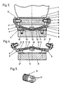
Im Nachstehenden wird vorerst anhand der Fig. 1 bis 5 der Vorderbacken näher erläutert. Der Skischuh 1 weist in der Schuhspitze einen querliegenden Bolzen 2 auf, an dessen Enden sich konische Vertiefungen 3 befinden. Es wäre auch möglich, daß diese Vertiefungen 3 von vorneherein in einer Schuhsohle vorgesehen sind. Ansonsten besteht die Möglichkeit, diesen Bolzen 2 nachträglich einzubringen.In the following, the toe pieces are first explained in more detail with reference to FIGS. 1 to 5. The
Dieser Vorderbacken weist Winkelhebel 4 auf, welche um eine Achse 5 parallel zur Skilängsrichtung verschwenkbar gehalten sind. Die schwenkbare Halterung erfolgt an Bolzen 7, welche in Lagerlaschen 7' eingelassen sind. Diese Lagerlaschen 7' sind Teil einer Grundplatte 6, welche über Schrauben 8' mit dem Skikörper 8 verbunden ist.This toe piece has
An den einen Armen der Winkelhebel 4 sind Spannteile 9 befestigt, welche in die Vertiefungen 3 an der Schuhspitze in Verriegelungsstellung eingreifen. Diese Spannteile 9 sind als an ihrem Einsatzende kegelstumpf- oder halbkugelförmig ausgebildete Zapfen ausgeführt, so daß eine rasche Zentrierung in den Vertiefungen 3 möglich ist. Vorteilhaft weisen diese Spannteile 9 an ihrem Außenumfang in Längsrichtung oder schraubenlinienförmig verlaufende Nuten 17 (siehe Fig. 5) auf, um möglicherweise vorhandenen Schnee aus den Vertiefungen 3 zu "bohren". Außerdem ist es in diesem Zusammenhang zweckmäßig, wenn die Spannteile 9 als Hülsen mit in Achsrichtung durchgehender Bohrung ausgebildet sind.On one arm of the
Um eine Einstellmöglichkeit beim Vorderbacken vorzusehen und damit einen Anpassung an verschiedene Schuhgrößen od. dgl. zu ermöglichen, sind die Spannteile 9 am einen Arm 4' eines jeden Winkelhebels 4 verstellbar, jedoch fixierbar gehalten. Die einfachste Möglichkeit liegt dabei darin, die Spannteile 9 als Zapfen mit einem Außengewinde auszubilden und in den Armen 4' der Winkelhebel 4 korrespondierende Gewindebohrungen vorzusehen. Für einen festen Halt der Spannteile 9 können dann zusätzlich noch Kontermuttern 16 vorgesehen werden. Durch diese Verstellmöglichkeit ist nicht nur eine Anpassung an verschiedene Schuhgrößen möglich, sondern es kann dadurch auch etwaiges Spiel oder Abnützung vermieden bzw. ausgeglichen werden.In order to provide an adjustment option for the front jaw and thus to allow adaptation to different shoe sizes or the like, the
Die Winkelhebel 4 sind auch Teile eines Schnappmechanismusses, der ein Öffnen und Schließen des Vorderbackens, d.h. ein Schwenken der Winkelhebel 4 erlauben soll.The angle levers 4 are also part of a snap mechanism which allows the front jaw to open and close, i.e. a pivoting of the
In Fig. 3 ist der Backen in der Verriegelungsstellung, also mit eingesetztem Schuh 1, gezeigt. Fig. 4 zeigt die geöffnete Ruhestellung des Vorderbackens.In Fig. 3 the jaw is shown in the locked position, that is with the
Die einen Arme 4' der Winkelhebel 4 eines Winkelhebelpaares tragen die Spannteile 9 und die anderen Arme 4 ' ' sind gegeneinander zur Skimitte hin gerichtet und über die bereits erwähnte Federeinrichtung bzw. einem Schnappmechanismus miteinander in Wirkverbindung stehend.The one arms 4 'of the angle levers 4 of a pair of angle levers carry the
Von den Enden der Arme 4" der beiden Winkelhebel 4 ragen Stangen 11 ab, deren freie Enden zu einem gemeinsamen Gelenk 10 führen, wobei die Stangen 11 in den Armen 4" und/oder in dem gemeinsamen Gelenk 10 verschiebbar eingreifen. Jeweils zwischen den Armen 4" und dem Gelenk 10 ist eine Feder 12 eingesetzt.
Das scharnierartige Gelenk 10, welches zweckmäßig wie auch aus der Zeichnung ersichtlich, als Schneidenlagerung ausgeführt ist, ist somit über die Stangen 11 mit den Winkelhebeln 4 verbunden. Die Federn sind als über die Stangen 11 geschobene Schraubenfedern 12 ausgebildet, welche also die Arme 4" der Winkelhebel 4 und das Gelenk 10 auseinanderzudrücken trachten. In der Mittellage, wenn also die Stangen 11 beider Winkelhebel 4 zueinander fluchten und parallel zur Skioberfläche stehen, werden die Federn 12 am stärksten zusammengedrückt. Von diesem Totpunkt aus können die Winkelhebel 4 nach beiden Seiten hin verschwenken, also entweder in die Lage nach Fig. 4 oder in die Lage nach Fig. 3.The hinge-like joint 10, which is expediently designed as a cutting edge bearing, as can also be seen from the drawing, is thus connected to the angle levers 4 via the
Um ein Öffnen des Schnappmechanismusses und ein Begrenzen der Bewegung des Gelenkes 10 nach oben hin zu ermöglichen, greift das Gelenk 10 in eine gabelförmige Öffnung eines Betätigungshebels 13 ein, welcher um eine quer zur Skilängsrichtung verlaufende Achse am Bolzen 14 schwenkbar gelagert ist. Auch dieser Bolzen 14 ist in Lagerlaschen 14' einer Grundplatte 6 gehalten.In order to make it possible to open the snap mechanism and to limit the movement of the joint 10 upwards, the joint 10 engages in a fork-shaped opening of an
Das der gabelförmigen Öffnung gegenüberliegende Ende des Betätigungshebels 13, also der am anderen Ende frei auskragende Arm dieses Betätigungshebels 13, weist eine um die Längsachse des Betätigungshebels 13 verdrehbare Exzenterscheibe 15 auf, wobei die größte Ausladung der Exzenterscheibe 15 annähernd dem Verschwenkweg dieses freien Endes des Betätigungshebels 13 entspricht. Dadurch können die beiden Endstellungen dieses Betätigungshebels 13 fixiert werden, wobei im einen Falle der Betätigungshebel 13 selbst an der Skioberfläche aufliegt und in der anderen Endstellung eine Abstützung durch die nach unten geschwenkte Exzenterscheibe 15 erfolgen kann. In der Ruhe stellung der Winkelhebel 4 ist dabei das Gelenk 4 oberhalb der Drehachse 5 der Winkelhebel 4. Dadurch ist bereits beim Auftreten mit der Sohle des Skischuhes ein Einrastvorgang des Vorderbackens auslösbar.The end of the actuating
Zwischen den Ästen der Gabel am einen Ende des Betätigungshebels 13 liegt das Gelenk 10. Ist der Vorderbacken geschlossen, wie dies in Fig. 2 dargestellt ist, dann kann durch Abwärtsdrücken des Betätigungshebels 13 mittels des Skistockes oder ähnlichem (die Exzenterscheibe muß bei dieser Bewegung natürlich nach oben weisen) das Gelenk 10 über den Totpunkt gedrückt werden. Somit wird der Schuh 1 im Bereich des Vorderbackens freigegeben. Beim Einsteigen in die Tourenbindung drückt die Schuhsohle auf den oberen Ast der Gabel des Betätigungshebels 13, bis das Gelenk 10 über den Totpunkt nach unten gebracht ist und die Bindung dann durch die Federbelastung von selbst zuschnappt.Between the branches of the fork at one end of the operating
Weist die Exzenterscheibe 15 nach oben, ist also der Betätigungshebel 13 verschwenkbar, ist es möglich, aufgrund der konischen Ausformung der Spannteile 9 und der Vertiefungen 3 den Skischuh 1 durch ein Drehmoment um die Hochachse des Schuhes 1 aus dem Vorderbacken zu drehen, wie es bei einem Drehsturz nötig ist. Dabei werden die Winkelhebel 4 nach außen gedrückt und der Betätigungshebel 13 schwenkt nach unten. Dieses Herausdrehen des Skischuhes ist schon -mit geringem Kraftaufwand möglich. Um daher beim Aufstieg nicht unbeabsichtigt aus dem Vorderbacken zu rutschen, muß die Schwenkmöglichkeit der Winkelhebel 4 unterbunden werden. Mit der Exzenterscheibe 15 kann der Betätigungshebel 13 arretiert werden. Der obere Teil der Gabel des Betätigungshebels 13 drückt dann das Gelenk 10 nach unten und verhindert damit ein Aufschnappen der Bindung. Für die Abfahrt muß die Exzenterscheibe 15 wieder nach oben gedreht werden, so daß der Betätigungshebel 13 wieder schwenkbar ist.If the
Die Fig. 6 bis 12 zeigen eine Konstruktionsvariante des Hinterbackens der Tourenbindung auf.6 to 12 show a design variant of the toe binding of the touring binding.
Für die Abfahrt beim Tourenskilauf muß die Schwenkbarkeit des Skischuhes 1 unterbunden werden können. Dazu wird eine Verriegelungsvorrichtung, die die Sicherheitsfunktionen für Frontal- und Drehsturz übernimmt, vorgeschlagen. Zusätzlich besitzt dieser Hinterbacken Bauteile, die als Steighilfe beim Gehen benützt werden können, was insbesondere bei steilen Anstiegsspuren von Vorteil ist. Die Fig. 6 bis 8 zeigen den Hinterbacken und den Fersenteil des Skischuhes in verriegelter Stellung.The pivotability of
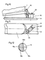
Der Hinterbacken besteht aus einem quaderförmigen Körper 18, der um einen am Ski 8 befestigten, annähernd rechtwinklig von der Skioberfläche abragenden Bolzen 19 drehbar gelagert ist. Der Bolzen 19 weist mehrere, plane Ausnehmungen auf, wie besonders der Fig. 12 entnommen werden kann. In einer Bohrung in Längsrichtung des Körpers 18 befindet sich eine Feder 20, die einen Kolben 21 gegen den Bolzen 19 drückt. Die Vorspannung der Feder 20 kann mit einer Einstellschraube 22 verändert werden. Bei einem Drehen des Backens aus der in Fig. 6 und Fig. 8 gezeigten Lage wird der Kolben 21 nach rückwärts bewegt und damit die Feder 20 zusammengedrückt, was ein rückdrehendes Moment zur Folge hat. Durch diese Bauweise ist es möglich, den Hinterbacken an den jeweils planen Flächen des Bolzens 19 einrasten zu lassen, also in den in den Fig. 8, 9 und 11 gezeigten Stellungen sowie auch quer zur Skilängsrichtung.The buttock consists of a
Der Körper 18 trägt weiters Stifte 23' aus federndem Material, welche mit korrespondierenden Vertiefungen am Fersenteil eines Skischuhes in Wirkverbindung bringbar sind. Diese frei auskragenden Stifte 23' werden zweckmäßig von den freien Enden eines U-förmigen Bügels 23 gebildet. Dieser Bügel 23 wird in entsprechenden Ausnehmungen am Körper 18 gehalten. Die Fixierung erfolgt durch Plättchen 24 sowie durch die aufgeschraubte Steighilfe 25.The
Die frei über den Körper auskragenden Enden (Stifte 23') des Bügels 23 lassen sich mit entsprechender Kraft etwas nach außen schwenken. Am Absatz des Schuhes 1 ist ein plättchenförmiger Beschlagteil 26 angeschraubt, welcher im wesentlichen als sich von oben nach unten verbreiternder Absatz ausgeführt ist und am oberen Abschluß Einraststellen aufweist. In diese Einraststellen können die Stifte 23' des Bügels 23 eingreifen. Anstelle eines aufschraubbaren Beschlagteiles 26 könnte selbstverständlich auch von vorneherein der Schuhabsatz entsprechend ausgeführt werden.The ends (pins 23 ') of the
Ist der Skischuh 1 schwenkbar im Vorderbacken verankert, so braucht nur der Fersenteil des Skischuhes hinuntergedrückt zu werden, so daß die frei auskragenden Stifte 23' des Bügels 23 über den keilförmigen Teil am Beschlag 26 auseinandergespreizt zu werden, bis diese beiden Enden des Bügels 23 in die Einraststellen (Vertiefungen) einrasten. Bei einem Frontalsturz wird bei einer bestimmten Kraft der Skischuh 1 wieder aus dieser Verriegelung herausgerissen. Die Größe der Auslösekraft ist von der Geometrie des Beschlagteiles 26 sowie von der Stärke des Bügels 23 abhängig.If the
Die seitliche Auslösung wird dadurch gewährleistet, daß sich der Schuh 1 direkt und zwar um eine Achse, die normal zur Skioberfläche liegt und annähernd durch einen der beiden Spannteile 9 des Vorderbackens läuft. Die Exzenterscheibe 15 darf dabei den Betätigungshebel 13 nicht verriegeln. Durch diese Drehung wird der Hinterbacken verschwenkt, bis sich der Skischuh 1 nicht mehr im Eingriff mit dem Backen befindet. Die Größe der seitlichen Auslösekraft ist mit der Einstellschraube veränderbar.The lateral triggering is ensured in that the
Aussteigen kann man aus der Bindung, indem man den Vorderbacken mit Hilfe des Betätigungshebels 13 öffnet.You can get out of the binding by opening the front jaw with the help of the operating
Die Schuhsohle berührt bei dieser Bindung nicht den Ski, sondern der Skischuh 1 ist am Vorder- und am Hinterbacken sozusagen aufgehängt. Zwischen dem Ski 8 und dem Schuh 1 ist ein gewisser Abstand vorhanden, was die Tourenbindung gegen das Anstollen von Schnee an der Schuhsohle unempfindlich macht. Dadurch wird auch die wechselnde Reibung zwischen der Schuhsohle und dem Ski bzw. den Bindungsteilen, welche insbesondere bei seitlicher Auslösung großen Einfluß haben kann, vermieden.With this binding, the sole of the shoe does not touch the ski, but the
Der Schuh 1 kann sich auch ein wenig in Längsrichtung im Hinterbacken verschieben, wodurch der Einfluß von Bindung und Schuh auf die Skibiegung stark vermindert wird.The
In Fig. 9 ist die Wirkungsweise der hohen Steighilfe 25 aufgezeigt. Wird der Hinterbacken um 180° aus der Abfahrtsstellung gedreht, rastet er aufgrund der Abflachungen 19a bis 19d an dem Bolzen 19 wiederum ein. Dadurch kann der Skischuh nicht mehr ganz zum Ski geschwenkt werden.The mode of operation of the
Für eine flachere Aufstiegsspur kann eine niedere Steighilfe benützt werden. Es wird diesbezüglich auf die Fig. 10 und 11 der Zeichnungen verwiesen. An der Steighilfe 25 kragt seitlich ein Arm aus. Wird der Hinterbacken so geschwenkt, daß er in einer ca. 45° zur Skilängsachse gelegenen Position einrastet, so ragt die niedere Steighilfe unter den Absatz und bewirkt, daß der Schuh nicht bis zum Ski geschwenkt werden kann.A lower climbing aid can be used for a flatter ascent track. In this regard, reference is made to FIGS. 10 and 11 of the drawings. On the climbing
Für kurze Abfahrten mit den Steigfellen ist es wünschenswert, die Ferse des Skischuhes zu fixieren. Eine einfache Möglichkeit besteht hier mit Hilfe der niederen Steighilfe. Wird der Skischuh 1 ganz am Ski 8 aufgesetzt, wie in Fig. 10 durch die strichlierte Linie angedeutet, und dann der Hinterbacken in die 45°-Position geschwenkt, kommt die niedere Steighilfe über den Schuhabsatz zu liegen und sperrt damit eine Aufwärtsbewegung des Skischuhes. Wird keine Steighilfe gewünscht, kann der Backen gänzlich quer zur Skilängsrichtung gestellt werden, wobei auch in dieser Stellung der Hinterbacken einrastet.For short descents with the climbing skins, it is desirable to fix the heel of the ski boot. An easy way is here with the help the lower climbing aid. If the
Im Rahmen der Erfindung sind selbstverständlich verschiedene Konstruktionsvarianten denkbar. So wäre es möglich, beim Vorderbacken anstelle jeweils einer Stange und einer Schraubenfeder 12 mehrere parallel zueinanderliegende Stangen 11 und Schraubenfedern 12 vorzusehen, um dadurch gegebenenfalls die Federwirkung zu verstärken. Aus den Fig. 3 und 4 ist auch ersichtlich, daß die Drehachse 5 der Winkelhebel 4 nicht im abgewinkelten Bereich dieser Winkelhebel 4 liegt, sondern weit im Bereich des Armes 4" des Winkelhebels 4. Dadurch kann ein ensprechend größerer Weg des Armes 4' des Winkelhebels 4 erreicht werden. Es sind hier also durch entsprechende Konstruktiosänderungen auch Funktionsverbesserungen denkbar.Various construction variants are of course conceivable within the scope of the invention. Thus, it would be possible to provide several
In der vorstehenden Beschreibung wurde stets davon gesprochen, daß im Spitzenbereich des Skischuhes 1 entsprechende Vertiefungen 3 vorgesehen sind, in welche zapfenartige Spannteile 9 eingreifen. Selbstverständlich kann im Rahmen der vorliegenden Erfindung auch eine konstruktive Umkehr vorgesehen werden, indem nämlich am Skischuh im Bereich der Schuhspitze seitlich vorstehende Bolzen vorgesehen sind, über welche ringförmige Spannteile, welche an den Winkelhebeln 4 montiert sind, greifen. Es wäre dabei auch denkbar, die Arme 4' der Winkelhebel 4 mit entsprechenden Ausnehmungen zum Übergreifen dieser Bolzen auszuführen.In the above description it was always said that corresponding depressions 3 are provided in the tip region of the
Claims (6)
Applications Claiming Priority (2)
| Application Number | Priority Date | Filing Date | Title |
|---|---|---|---|
| AT0087385A AT381458B (en) | 1985-03-25 | 1985-03-25 | TOURING SKI BINDING |
| AT873/85 | 1985-03-25 |
Publications (3)
| Publication Number | Publication Date |
|---|---|
| EP0199098A2 EP0199098A2 (en) | 1986-10-29 |
| EP0199098A3 EP0199098A3 (en) | 1987-04-29 |
| EP0199098B1 true EP0199098B1 (en) | 1990-02-28 |
Family
ID=3501783
Family Applications (1)
| Application Number | Title | Priority Date | Filing Date |
|---|---|---|---|
| EP86103810A Expired - Lifetime EP0199098B1 (en) | 1985-03-25 | 1986-03-20 | Cross-country ski binding |
Country Status (3)
| Country | Link |
|---|---|
| EP (1) | EP0199098B1 (en) |
| AT (1) | AT381458B (en) |
| DE (1) | DE3669112D1 (en) |
Cited By (14)
| Publication number | Priority date | Publication date | Assignee | Title |
|---|---|---|---|---|
| EP1559457A1 (en) | 2004-01-28 | 2005-08-03 | Fritz Dipl.-Ing. Barthel | Bearing plate and shoe for the binding of a cross-country touring ski |
| DE19631164B4 (en) * | 1996-08-01 | 2008-08-21 | Rottefella As | Cross-country or touring ski binding and ski boot for it |
| WO2009105866A1 (en) * | 2008-02-29 | 2009-09-03 | G3 Genuine Guide Gear Inc. | Heel unit for alpine touring binding |
| WO2009121187A1 (en) * | 2008-04-03 | 2009-10-08 | G3 Genuine Guide Gear Inc. | Toe unit for alpine touring binding |
| EP2272574A1 (en) | 2009-07-10 | 2011-01-12 | Fritschi AG - Swiss Bindings | Climbing aid for a ski |
| DE202010000614U1 (en) * | 2010-01-05 | 2011-05-26 | Salewa Sport Ag | Ski boot and binding system comprising a ski boot and a ski binding |
| EP2368608A1 (en) | 2010-03-23 | 2011-09-28 | Fritschi AG - Swiss Bindings | Climbing aid |
| DE102011078834A1 (en) | 2011-07-07 | 2013-01-10 | Micado Cad-Solutions Gmbh | Holding system for tour ski attachment for holding ski boot on ski, has base body which is attached to ski and bracket having two bars, where two bars are connected with each other to common connecting area |
| EP2656884A1 (en) | 2012-04-25 | 2013-10-30 | MARKER Deutschland GmbH | Lightweight ski binding with increased release security |
| DE202013009713U1 (en) | 2012-12-10 | 2014-02-06 | Skis Rossignol | Brake device for a touring ski with integrated adjustable ascent wedge |
| US8746729B2 (en) | 2012-10-22 | 2014-06-10 | Salomon S.A.S. | Toe piece for gliding apparatus and gliding apparatus equipped with such binding |
| US8820772B2 (en) | 2011-09-13 | 2014-09-02 | Salewa Sportgeraete Gmbh | Heel unit for a touring binding |
| EP2989918A1 (en) | 2014-08-29 | 2016-03-02 | MARKER Deutschland GmbH | Ski boot with coated pin holder |
| US10463946B2 (en) | 2017-06-07 | 2019-11-05 | G3 Genuine Guide Gear Inc. | Touring binding heel unit |
Families Citing this family (114)
| Publication number | Priority date | Publication date | Assignee | Title |
|---|---|---|---|---|
| IT1204195B (en) * | 1986-04-30 | 1989-03-01 | Nordica Spa | CROSS-COUNTRY FOOTWEAR-SKI CONNECTION DEVICE |
| DE3640220A1 (en) * | 1986-11-25 | 1988-06-09 | Richard Erlebach | Ski binding |
| FR2673364A1 (en) * | 1991-02-28 | 1992-09-04 | Servit | Ski holder |
| AT396553B (en) * | 1991-06-21 | 1993-10-25 | Barthel Fritz | BAKING FOR TOURING SKI BINDING |
| AT402020B (en) * | 1993-08-19 | 1997-01-27 | Barthel Fritz | Heel jaw for a ski binding |
| ITMI20051429A1 (en) * | 2005-07-22 | 2007-01-23 | Ski Trab S R L | TIP FOR SKI ATTACHMENTS |
| ITTO20070377A1 (en) * | 2007-05-29 | 2008-11-30 | Scarpa Calzaturificio Spa | LOCKING SYSTEM TO COUPLE A MOUNTAIN BOOT TO A SKI OF ALPINE |
| ITVE20070024U1 (en) | 2007-07-05 | 2009-01-06 | Ober Alp Spa | PERFECT SKI SHOE |
| DE102008050044B4 (en) * | 2008-10-01 | 2017-05-11 | Marker Deutschland Gmbh | ski binding |
| FR2945185B1 (en) * | 2009-05-05 | 2011-10-07 | Gignoux Sarl | SKI FIXING DEVICE FOR HIKING |
| IT1395134B1 (en) * | 2009-08-05 | 2012-09-05 | Ski Trab S R L | MORE-POSSIBLE HORSEBACK AND FACILITATED FASTENING / RELEASING FOR MOUNTAIN SKI ATTACKS. |
| IT1396339B1 (en) * | 2009-10-06 | 2012-11-16 | Roberto Giordani | TIP OF LOCKED MOUNTABLE SKI ATTACKS |
| DE202010001835U1 (en) | 2010-02-04 | 2011-06-09 | Salewa Sport Ag | Touring ski binding with a mounting hole assembly having a base plate and base plate |
| EP2319595B1 (en) | 2009-11-04 | 2014-08-13 | Salewa Sport AG | Cross-country ski binding with a base plate comprising a fixing hole assembly and base plate |
| DE102009046396A1 (en) | 2009-11-04 | 2011-05-05 | Salewa Sport Ag | Toe piece for touring ski binding and ski boot for touring ski binding |
| DE102010001130A1 (en) | 2010-01-22 | 2011-07-28 | Salewa Sport Ag | Touring ski binding with a bearing pin having a snow groove |
| IT1397478B1 (en) † | 2010-01-19 | 2013-01-16 | Atk Race Srl | TALLONIERA FOR AN ALPINE MOUNTAIN SKI ATTACK |
| IT1397694B1 (en) * | 2010-01-22 | 2013-01-24 | Atk Race Srl | TIP FOR SKI-MOUNTAIN ATTACKS. |
| DE102010006218A1 (en) * | 2010-01-29 | 2011-08-04 | MARKER Deutschland GmbH, 82377 | Ski binding with climbing aid |
| FR2957264B1 (en) * | 2010-03-09 | 2019-05-17 | Eurl Gignoux | SYSTEM FOR FIXING A SHOE ON A SLIDING GEAR |
| DE102010028764A1 (en) | 2010-05-07 | 2011-11-10 | Salewa Sport Ag | Heel unit for a binding, in particular touring ski binding |
| DE102010029647A1 (en) | 2010-06-02 | 2011-12-08 | Salewa Sport Ag | touring binding |
| IT1401139B1 (en) * | 2010-07-23 | 2013-07-12 | Ski Trab S R L | ALPINISTIC SKI BOOTS WITH HEEL WITH HOOKING MEANS FOR TALLONIERE OF ALPINISTIC SKI ATTACKS |
| DE102010039475B4 (en) | 2010-08-18 | 2022-01-20 | Salewa Sport Ag | Coupling element for a ski boot and ski boot |
| WO2012024809A1 (en) | 2010-08-27 | 2012-03-01 | Fritschi Ag - Swiss Bindings | Touring heel binding having a dynamic sliding range |
| DE102010040928A1 (en) | 2010-09-16 | 2012-03-22 | Salewa Sport Ag | Gleitbrettbindung, especially touring ski binding |
| ITTO20110075A1 (en) * | 2011-01-31 | 2012-08-01 | Marco Rigat | SECURITY TIP FOR MOUNTAIN SKI ATTACK. |
| DE102010043880B4 (en) | 2010-11-12 | 2021-10-07 | Salewa Sport Ag | Heel unit with wear-reducing design and bracket element for such a heel unit |
| DE102010043879A1 (en) | 2010-11-12 | 2012-05-16 | Salewa Sport Ag | Touring binding with release mechanism and locking mechanism |
| ITVI20100061U1 (en) | 2010-12-21 | 2012-06-22 | Rocca Di Rosato L & C Snc | SKI BOOT |
| ITTV20110038A1 (en) * | 2011-03-14 | 2012-09-15 | Tasci S R L | ATTACK FOR THE ANCHORING OF A BOOT FROM SCIALPINISMO ON A SKIING TO DOWNLOAD OR SIMILAR |
| ITTO20110331A1 (en) * | 2011-04-11 | 2012-10-12 | Stefano Maruelli | INNOVATIVE BLOCK SYSTEM FOR ATTACKS BITCHES. |
| ITMI20110839A1 (en) * | 2011-05-13 | 2012-11-14 | Colibri Di Murada Ivan | SKI ATTACK SYSTEM. |
| ITVI20110141A1 (en) * | 2011-05-27 | 2012-11-28 | Roberto Giordani | RELEASE DEVICE FOR TALLONIERE OF ATTACKS FROM SKI MOUNTAINS |
| CH705063A1 (en) * | 2011-05-31 | 2012-12-14 | Fritschi Ag Swiss Bindings | Ski binding. |
| ITTO20110598A1 (en) | 2011-07-07 | 2013-01-08 | Elmi S R L | TIP FOR SKI CONNECTION OR SNOWSHOES WITH MAGNETIC SELF-CENTERING SYSTEM |
| DE102011079210A1 (en) | 2011-07-14 | 2013-01-17 | Salewa Sport Ag | Heel unit for a touring ski binding |
| CH705579A2 (en) | 2011-09-29 | 2013-04-15 | Fritschi Ag Swiss Bindings | Front machine. |
| DE102012201816B4 (en) | 2012-02-07 | 2022-10-20 | Fritz Barthel | Front unit for a gliding board binding having first and second engagement means |
| FR2986975B1 (en) | 2012-02-22 | 2017-05-12 | Salomon Sas | VERSATILE FIXATION OF A SHOE ON A SLIDING BOARD |
| DE202012002705U1 (en) | 2012-03-14 | 2013-06-17 | Salewa Sport Ag | Heel unit for a touring binding |
| DE102012205858B4 (en) | 2012-04-11 | 2019-08-14 | Fritz Barthel | Gliding board shoe and front unit for a board gliding |
| DE102012206880A1 (en) | 2012-04-25 | 2013-10-31 | Salewa Sport Ag | Front unit for a board binding, in particular pivotable front unit with release arrangement |
| ITBO20120243A1 (en) * | 2012-05-04 | 2013-11-05 | Atk Race Srl | TIP FOR SKI-MOUNTAINEER'S ATTACK |
| ITTV20120077A1 (en) | 2012-05-08 | 2013-11-09 | Scarpa Calzaturificio Spa | SKI BOOT |
| DE102012207959B4 (en) | 2012-05-11 | 2020-11-12 | Fritz Barthel | Front unit of a gliding board binding and gliding board binding |
| DE102012208915A1 (en) | 2012-05-25 | 2013-11-28 | Salewa Sport Ag | Heel unit with climbing aid and brake assembly |
| US8833793B2 (en) | 2012-06-15 | 2014-09-16 | Fritschi Ag-Swiss Bindings | Skibindung |
| FR2993470B1 (en) | 2012-07-19 | 2015-05-29 | Salomon Sas | DEVICES FOR RETAINING BEFORE A SLIDING BOARD |
| FR2994099B1 (en) | 2012-08-06 | 2014-09-26 | Salomon Sas | REMOVABLE REMOVABLE DEVICE FOR SNOWBOARD BOARD |
| US8827302B2 (en) | 2012-09-11 | 2014-09-09 | Fritschi Ag-Swiss Bindings | Automatic heel unit for a ski binding |
| EP2705883B1 (en) | 2012-09-11 | 2015-07-29 | Fritschi AG - Swiss Bindings | Automatic heel device for a ski binding |
| ITTO20120801A1 (en) * | 2012-09-15 | 2014-03-16 | Stefano Maruelli | IRROBUSTED ATTACK SYSTEM |
| ITTV20120203A1 (en) | 2012-10-26 | 2014-04-27 | Scarpa Calzaturificio Spa | SKI BOOT |
| FR2997309B1 (en) | 2012-10-29 | 2016-01-22 | Salomon Sas | SKI FIXING RETENTION DEVICE WITH SEPARATE MOUNTING RODS |
| EP2754469B1 (en) | 2013-01-10 | 2015-12-30 | Fritschi AG - Swiss Bindings | Tilting crampon |
| DE102014001255A1 (en) * | 2013-02-06 | 2014-08-07 | Reinhold Zoor | Safety heel ski binding for ski boot, has housing swingably supported transversely to ski and parallel to ski running axles, so that heel holder swings-out around tip of ski boot from circular path of heel in rise position |
| DE102013003930A1 (en) * | 2013-03-08 | 2014-09-11 | Reinhold Zoor | Remote-controlled toe lock |
| EP2813268A1 (en) | 2013-06-12 | 2014-12-17 | Fritschi AG - Swiss Bindings | Front automat |
| FR3007663B1 (en) * | 2013-06-28 | 2016-12-30 | Rossignol Sa | FASTENING A SHOE WITH JAW WITH CLEARANCE OF MATERIAL |
| US9242167B2 (en) | 2013-07-09 | 2016-01-26 | G3 Genuine Guide Gear Inc. | Ski binding heel unit |
| EP2829188B1 (en) | 2013-07-25 | 2018-05-09 | Rossignol Lange S.R.L. | Ski boot |
| EP2829187B1 (en) | 2013-07-25 | 2016-07-13 | Rossignol Lange S.R.L. | Ski boot |
| DE102013221778A1 (en) | 2013-10-25 | 2015-04-30 | Salewa Sport Ag | Heel unit for a touring binding |
| DE102013224576B4 (en) * | 2013-11-29 | 2019-03-28 | Salewa Sport Ag | Slide board binding with pivot bearing |
| FR3015907A1 (en) | 2013-12-30 | 2015-07-03 | Salomon Sas | SLIDING GEAR |
| FR3016798A1 (en) * | 2014-01-24 | 2015-07-31 | Pierre Mouyade | TELEMARK SKI AUTOMATIC LOCKING FIXATION, HIKING SKI OR BACKGROUND SKIING |
| EP2929919B1 (en) | 2014-04-09 | 2018-05-30 | Salomon S.A.S. | Ski binding |
| EP2932863A1 (en) | 2014-04-16 | 2015-10-21 | Calzaturificio S.C.A.R.P.A. S.p.A. | Ski boot |
| FR3021228A1 (en) | 2014-05-20 | 2015-11-27 | Pascal Pierre Nobile | FRONT STOP FIXING SKI HIKING |
| EP2965791B1 (en) | 2014-07-08 | 2019-03-27 | Fritschi AG - Swiss Bindings | Front pin ski binding boot positioning unit |
| NO2683913T3 (en) * | 2014-08-20 | 2018-03-17 | ||
| FR3026311A1 (en) | 2014-09-26 | 2016-04-01 | Salomon Sas | TALONNIERE FIXING A SHOE ON A BOARD OF SLIDING |
| FR3028724B1 (en) | 2014-11-24 | 2017-06-16 | Salomon Sas | COUPLING PLATE FOR SKI SHOE |
| EP3053633A1 (en) * | 2015-02-03 | 2016-08-10 | Atk Race S.R.L. | A device for transporting persons and/or articles in snowy and/or icy conditions |
| EP3115089B1 (en) | 2015-07-07 | 2019-02-27 | Fritschi AG - Swiss Bindings | Heel unit |
| DE202015005560U1 (en) | 2015-08-04 | 2016-11-07 | Salewa AG | Skibremsensystem |
| ITUB20153027A1 (en) | 2015-08-10 | 2017-02-10 | Scarpa Calzaturificio Spa | SKI BOOT |
| DE102016014950A1 (en) | 2015-12-18 | 2017-06-22 | Mark Richard Mosher | Improved heel freedom for touring ski binding |
| FR3046082B1 (en) | 2015-12-23 | 2018-01-12 | Salomon Sas | SKI FIXING |
| DE102016000609B4 (en) | 2016-01-23 | 2019-03-28 | Markus Steinke | Buttock device for a touring ski binding |
| DE102016006850A1 (en) * | 2016-02-17 | 2017-08-31 | Reinhold Zoor | Ski boot holder with swiveling tread spur |
| DE102016204563B4 (en) | 2016-03-18 | 2021-09-23 | Salewa Sport Ag | Front unit for a gliding board |
| DE102016204555A1 (en) * | 2016-03-18 | 2017-09-21 | Fritz Barthel | Front unit for a sliding board |
| EP3266504A1 (en) | 2016-07-07 | 2018-01-10 | Fritschi AG - Swiss Bindings | Ski binding |
| IT201600092338A1 (en) * | 2016-09-14 | 2018-03-14 | La Sportiva S P A | BOOT, PARTICULARLY FOR SCALPINISM OR TELEMARK. |
| EP3345659B1 (en) | 2017-01-04 | 2019-06-26 | Fritschi AG - Swiss Bindings | Automated heelholder device for a ski binding |
| FR3066700B1 (en) * | 2017-05-29 | 2022-06-03 | Felisaz S A S | REAR ATTACHMENT DEVICE FOR TOURING SKIS WITH SKI BRAKE LOCKING DEVICE |
| DE102017120701A1 (en) * | 2017-09-07 | 2019-03-07 | Marker Deutschland Gmbh | Ultralight forehead |
| IT201700116389A1 (en) * | 2017-10-16 | 2019-04-16 | Stefano Maruelli | LIGHT ATTACK SYSTEM WITH SIDE RELEASE MULTIFUNCTION LEVER |
| US10315099B2 (en) | 2017-10-31 | 2019-06-11 | G3 Genuine Guide Gear Inc. | Lightweight touring binding heel unit |
| FR3072884B1 (en) * | 2017-11-02 | 2022-01-21 | Rossignol Sa | SHOE FIXING DEVICE STOP |
| IT201800000399A1 (en) * | 2018-01-03 | 2019-07-03 | Atk Race Srl | SKI ATTACHMENT TOE |
| SK8337Y1 (en) | 2018-02-20 | 2019-01-08 | Gaborik Jozef | Front unit of a ski binding |
| EP3566754B1 (en) | 2018-05-08 | 2022-08-17 | Fritschi AG - Swiss Bindings | Front skibinding |
| EP3702005A1 (en) | 2018-06-14 | 2020-09-02 | Fritschi AG - Swiss Bindings | Heelholder |
| WO2020010477A1 (en) * | 2018-07-09 | 2020-01-16 | Priest Ryan | Ski binding |
| DE102018125546A1 (en) * | 2018-10-15 | 2020-04-16 | Marker Deutschland Gmbh | Toe pieces |
| IT201900013143A1 (en) * | 2019-07-29 | 2021-01-29 | Atk Sports S R L | SKI ATTACHMENT TOE FOR SKI MOUNTAINEERING |
| DE102019127792A1 (en) * | 2019-10-15 | 2021-04-15 | Marker Deutschland Gmbh | Clamping lever as a punched or cut part |
| EP3851174A1 (en) | 2020-01-16 | 2021-07-21 | Fritschi AG - Swiss Bindings | Front unit for a ski binding |
| FR3106501B1 (en) | 2020-01-24 | 2022-04-15 | The M Equipment | Front stop for gliding device, and gliding device equipped with such a front stop |
| EP3854465A1 (en) | 2020-01-24 | 2021-07-28 | The M Equipment | Front binding for a gliding device and gliding device provided with such a front binding |
| DE102020203278A1 (en) | 2020-03-13 | 2021-09-16 | Salewa Sport Ag | Front unit for a ski binding with a magnetic entry aid |
| DE102020203271A1 (en) | 2020-03-13 | 2021-09-16 | Salewa Sport Ag | HEEL UNIT WITH RELEASE AND ADJUSTMENT MECHANISM |
| DE102020203280A1 (en) | 2020-03-13 | 2021-09-16 | Salewa Sport Ag | Front unit for a ski binding with a defined opening dimension |
| DE102020203281A1 (en) | 2020-03-13 | 2021-09-16 | Salewa Sport Ag | FRONT UNIT FOR A SKI BINDING WITH AN ENTRY AID |
| AT524097A1 (en) * | 2020-07-17 | 2022-02-15 | Christoph Beisteiner | Climbing aid for a touring ski binding |
| AT524027B1 (en) | 2020-09-29 | 2022-02-15 | Schabel Dipl Ing Christoph | SHELL BOOT |
| EP3995185A1 (en) * | 2020-11-06 | 2022-05-11 | Lukas Ernst | Heel unit for touring ski binding with automatic climbing wedge adjustment and method for positioning shoe supports |
| FR3116208B1 (en) | 2020-11-13 | 2023-04-28 | The M Equipment | Protective device for the front stop of a gliding machine, its use, and front stop thus equipped |
| DE102021131143A1 (en) | 2021-11-26 | 2023-06-01 | Salewa Sport Ag | Heel unit of a touring binding, comprising a one-piece climbing aid with multiple support options |
| DE102022106276A1 (en) | 2022-03-17 | 2023-09-21 | Salewa Sport Ag | Heel unit for a sliding board binding with Mz release via cam body |
| FR3136383A1 (en) | 2022-06-10 | 2023-12-15 | Salomon S.A.S. | Device for retaining a shoe on a sliding board and sliding machine comprising such a device |
Family Cites Families (6)
| Publication number | Priority date | Publication date | Assignee | Title |
|---|---|---|---|---|
| DE2063163A1 (en) * | 1970-12-22 | 1972-06-29 | Wiener Metallwarenfabrik Smolka & Co., Wien | Ski safety binding |
| AT315042B (en) * | 1972-07-13 | 1974-05-10 | Smolka & Co Wiener Metall | Ski binding |
| DE2657257A1 (en) * | 1976-12-17 | 1978-06-29 | Ver Baubeschlag Gretsch Co | Ski binding for cross-country skis - has spring steel clip moulded in heel or ski boot during mfr. |
| DE2907359A1 (en) * | 1979-02-24 | 1980-08-28 | Ver Baubeschlag Gretsch Co | Safety binding for long distance ski - includes front binding section providing side hold to front of boot sole with separate release devices |
| US4348036A (en) * | 1980-08-19 | 1982-09-07 | Settembre Richard J | Safety binding for nordic skis |
| AT368901B (en) * | 1980-09-16 | 1982-11-25 | Tyrolia Freizeitgeraete | TOURING DEVICE |
-
1985
- 1985-03-25 AT AT0087385A patent/AT381458B/en not_active IP Right Cessation
-
1986
- 1986-03-20 EP EP86103810A patent/EP0199098B1/en not_active Expired - Lifetime
- 1986-03-20 DE DE8686103810T patent/DE3669112D1/en not_active Expired - Lifetime
Cited By (20)
| Publication number | Priority date | Publication date | Assignee | Title |
|---|---|---|---|---|
| DE19631164B4 (en) * | 1996-08-01 | 2008-08-21 | Rottefella As | Cross-country or touring ski binding and ski boot for it |
| EP1559457A1 (en) | 2004-01-28 | 2005-08-03 | Fritz Dipl.-Ing. Barthel | Bearing plate and shoe for the binding of a cross-country touring ski |
| WO2009105866A1 (en) * | 2008-02-29 | 2009-09-03 | G3 Genuine Guide Gear Inc. | Heel unit for alpine touring binding |
| EP2259850A4 (en) * | 2008-02-29 | 2014-09-03 | G3 Genuine Guide Gear Inc | Heel unit for alpine touring binding |
| WO2009121187A1 (en) * | 2008-04-03 | 2009-10-08 | G3 Genuine Guide Gear Inc. | Toe unit for alpine touring binding |
| EP2556866A1 (en) | 2009-07-10 | 2013-02-13 | Fritschi AG - Swiss Bindings | Climbing aid for a ski |
| EP2272574A1 (en) | 2009-07-10 | 2011-01-12 | Fritschi AG - Swiss Bindings | Climbing aid for a ski |
| DE202010000614U1 (en) * | 2010-01-05 | 2011-05-26 | Salewa Sport Ag | Ski boot and binding system comprising a ski boot and a ski binding |
| US8793905B2 (en) | 2010-01-05 | 2014-08-05 | Salewa Sport Ag | Ski boot and binding system comprising a ski boot and a ski binding |
| EP2368608A1 (en) | 2010-03-23 | 2011-09-28 | Fritschi AG - Swiss Bindings | Climbing aid |
| DE102011078834A1 (en) | 2011-07-07 | 2013-01-10 | Micado Cad-Solutions Gmbh | Holding system for tour ski attachment for holding ski boot on ski, has base body which is attached to ski and bracket having two bars, where two bars are connected with each other to common connecting area |
| US8820772B2 (en) | 2011-09-13 | 2014-09-02 | Salewa Sportgeraete Gmbh | Heel unit for a touring binding |
| EP2656884A1 (en) | 2012-04-25 | 2013-10-30 | MARKER Deutschland GmbH | Lightweight ski binding with increased release security |
| DE102012206879A1 (en) | 2012-04-25 | 2013-10-31 | Marker Deutschland Gmbh | Lightweight ski binding with increased trigger safety |
| DE102012206879B4 (en) | 2012-04-25 | 2021-12-23 | Marker Deutschland Gmbh | Lightweight ski binding with increased release security with support device |
| US8746729B2 (en) | 2012-10-22 | 2014-06-10 | Salomon S.A.S. | Toe piece for gliding apparatus and gliding apparatus equipped with such binding |
| DE202013009713U1 (en) | 2012-12-10 | 2014-02-06 | Skis Rossignol | Brake device for a touring ski with integrated adjustable ascent wedge |
| EP2989918A1 (en) | 2014-08-29 | 2016-03-02 | MARKER Deutschland GmbH | Ski boot with coated pin holder |
| DE102014112472A1 (en) | 2014-08-29 | 2016-03-03 | Marker Deutschland Gmbh | Ski boot with coated pin holder |
| US10463946B2 (en) | 2017-06-07 | 2019-11-05 | G3 Genuine Guide Gear Inc. | Touring binding heel unit |
Also Published As
| Publication number | Publication date |
|---|---|
| AT381458B (en) | 1986-10-27 |
| ATA87385A (en) | 1986-03-15 |
| EP0199098A2 (en) | 1986-10-29 |
| EP0199098A3 (en) | 1987-04-29 |
| DE3669112D1 (en) | 1990-04-05 |
Similar Documents
| Publication | Publication Date | Title |
|---|---|---|
| EP0199098B1 (en) | Cross-country ski binding | |
| DE2502956C2 (en) | Sole hold-down for a ski safety binding | |
| EP1559455B1 (en) | Binding for a touring ski | |
| DE3151584A1 (en) | TOTAL BINDING OF A SHOE WITH A SKI, ESPECIALLY A CROSS-COUNTRY SKI | |
| DE3442780A1 (en) | ALPINE SKI SHOE | |
| EP2319596B1 (en) | Toe iron for a cross-country ski binding and ski shoe for a cross-country ski binding | |
| AT376900B (en) | SAFETY SKI BINDING | |
| DE2612708A1 (en) | SKI BRAKE | |
| WO1990003830A1 (en) | Front clamp | |
| EP0581802B1 (en) | Sports boot | |
| DE2359490A1 (en) | FRONT ABUTMENT FOR A SAFETY BINDING FOR SKI | |
| EP1194193A1 (en) | Device for linking a sports equipment with a shoe | |
| DE1578959C3 (en) | Heel support device for safety ski bindings | |
| DE2449369A1 (en) | SAFETY BINDING FOR SKI | |
| DE1478212B2 (en) | Release heel holder for ski bindings | |
| EP0061590B1 (en) | Ski brake | |
| DE3202267A1 (en) | HEEL HOLDER OF A SKI BINDING WITH SKI BRAKE | |
| DE4424737C1 (en) | Snow=board binding with boot drivers | |
| EP0426050B1 (en) | Front jaw | |
| DE2528578A1 (en) | SAFETY BINDING FOR SKI BOOTS | |
| DE2705215A1 (en) | HEEL OR SOLE HOLDER ON A SOLE PLATE OF A SKI BINDING AND SOLE PLATE WITH SUCH A HOLDER | |
| WO1990000078A1 (en) | Ski safety binding | |
| EP0128243B1 (en) | Releasable ski binding | |
| DE2707838A1 (en) | SAFETY SKI BINDING WITH A SOLE HOLDER SWIVELING ON A BASE BODY AND A BUILT-IN SKI BRAKE | |
| EP0113415B1 (en) | Safety binding for a touring ski |
Legal Events
| Date | Code | Title | Description |
|---|---|---|---|
| PUAI | Public reference made under article 153(3) epc to a published international application that has entered the european phase |
Free format text: ORIGINAL CODE: 0009012 |
|
| AK | Designated contracting states |
Kind code of ref document: A2 Designated state(s): CH DE FR IT LI |
|
| RAP1 | Party data changed (applicant data changed or rights of an application transferred) |
Owner name: BARTHEL, FRITZ, DIPL.-ING. |
|
| PUAL | Search report despatched |
Free format text: ORIGINAL CODE: 0009013 |
|
| AK | Designated contracting states |
Kind code of ref document: A3 Designated state(s): CH DE FR IT LI |
|
| 17P | Request for examination filed |
Effective date: 19870702 |
|
| 17Q | First examination report despatched |
Effective date: 19880920 |
|
| GRAA | (expected) grant |
Free format text: ORIGINAL CODE: 0009210 |
|
| AK | Designated contracting states |
Kind code of ref document: B1 Designated state(s): CH DE FR IT LI |
|
| REF | Corresponds to: |
Ref document number: 3669112 Country of ref document: DE Date of ref document: 19900405 |
|
| ITF | It: translation for a ep patent filed |
Owner name: INTERPATENT ST.TECN. BREV. |
|
| ET | Fr: translation filed | ||
| PLBE | No opposition filed within time limit |
Free format text: ORIGINAL CODE: 0009261 |
|
| STAA | Information on the status of an ep patent application or granted ep patent |
Free format text: STATUS: NO OPPOSITION FILED WITHIN TIME LIMIT |
|
| 26N | No opposition filed | ||
| ITTA | It: last paid annual fee | ||
| PGFP | Annual fee paid to national office [announced via postgrant information from national office to epo] |
Ref country code: DE Payment date: 20050317 Year of fee payment: 20 |
|
| PGFP | Annual fee paid to national office [announced via postgrant information from national office to epo] |
Ref country code: IT Payment date: 20050324 Year of fee payment: 20 |
|
| PGFP | Annual fee paid to national office [announced via postgrant information from national office to epo] |
Ref country code: FR Payment date: 20050330 Year of fee payment: 20 |
|
| PGFP | Annual fee paid to national office [announced via postgrant information from national office to epo] |
Ref country code: CH Payment date: 20050622 Year of fee payment: 20 |