EP2829188B1 - Ski boot - Google Patents
Ski boot Download PDFInfo
- Publication number
- EP2829188B1 EP2829188B1 EP13425107.3A EP13425107A EP2829188B1 EP 2829188 B1 EP2829188 B1 EP 2829188B1 EP 13425107 A EP13425107 A EP 13425107A EP 2829188 B1 EP2829188 B1 EP 2829188B1
- Authority
- EP
- European Patent Office
- Prior art keywords
- ski boot
- sole pad
- ski
- sole
- boot
- Prior art date
- Legal status (The legal status is an assumption and is not a legal conclusion. Google has not performed a legal analysis and makes no representation as to the accuracy of the status listed.)
- Active
Links
- 239000000463 material Substances 0.000 claims description 48
- 239000004033 plastic Substances 0.000 claims description 46
- 229920003023 plastic Polymers 0.000 claims description 46
- 230000002787 reinforcement Effects 0.000 claims description 37
- 239000002184 metal Substances 0.000 claims description 31
- 238000004519 manufacturing process Methods 0.000 claims description 17
- 238000002347 injection Methods 0.000 claims description 14
- 239000007924 injection Substances 0.000 claims description 14
- OKTJSMMVPCPJKN-UHFFFAOYSA-N Carbon Chemical compound [C] OKTJSMMVPCPJKN-UHFFFAOYSA-N 0.000 claims description 3
- 229910052799 carbon Inorganic materials 0.000 claims description 3
- 239000003365 glass fiber Substances 0.000 claims description 3
- 239000000243 solution Substances 0.000 description 8
- 239000000835 fiber Substances 0.000 description 7
- 238000000034 method Methods 0.000 description 6
- 230000008901 benefit Effects 0.000 description 4
- 229920002635 polyurethane Polymers 0.000 description 4
- 239000004814 polyurethane Substances 0.000 description 4
- 239000004917 carbon fiber Substances 0.000 description 3
- 230000009194 climbing Effects 0.000 description 3
- 229920000049 Carbon (fiber) Polymers 0.000 description 2
- 239000000654 additive Substances 0.000 description 2
- 230000000996 additive effect Effects 0.000 description 2
- 238000004873 anchoring Methods 0.000 description 2
- 229920001971 elastomer Polymers 0.000 description 2
- -1 polypropylene Polymers 0.000 description 2
- 239000005060 rubber Substances 0.000 description 2
- 230000009466 transformation Effects 0.000 description 2
- 241000909536 Gobiesocidae Species 0.000 description 1
- 229920002302 Nylon 6,6 Polymers 0.000 description 1
- 239000004952 Polyamide Substances 0.000 description 1
- 239000004698 Polyethylene Substances 0.000 description 1
- 239000004743 Polypropylene Substances 0.000 description 1
- 239000004760 aramid Substances 0.000 description 1
- 229920003235 aromatic polyamide Polymers 0.000 description 1
- 230000008859 change Effects 0.000 description 1
- 230000002950 deficient Effects 0.000 description 1
- 230000000694 effects Effects 0.000 description 1
- 239000000945 filler Substances 0.000 description 1
- 238000003754 machining Methods 0.000 description 1
- 238000012423 maintenance Methods 0.000 description 1
- 230000007246 mechanism Effects 0.000 description 1
- 238000000465 moulding Methods 0.000 description 1
- 229920002647 polyamide Polymers 0.000 description 1
- 229920000573 polyethylene Polymers 0.000 description 1
- 229920001155 polypropylene Polymers 0.000 description 1
- 230000008569 process Effects 0.000 description 1
- 230000003014 reinforcing effect Effects 0.000 description 1
- 239000012783 reinforcing fiber Substances 0.000 description 1
- 229920001169 thermoplastic Polymers 0.000 description 1
Images


Classifications
-
- A—HUMAN NECESSITIES
- A43—FOOTWEAR
- A43B—CHARACTERISTIC FEATURES OF FOOTWEAR; PARTS OF FOOTWEAR
- A43B5/00—Footwear for sporting purposes
- A43B5/04—Ski or like boots
- A43B5/0496—Ski or like boots boots for touring or hiking skis
-
- A—HUMAN NECESSITIES
- A43—FOOTWEAR
- A43B—CHARACTERISTIC FEATURES OF FOOTWEAR; PARTS OF FOOTWEAR
- A43B5/00—Footwear for sporting purposes
- A43B5/04—Ski or like boots
- A43B5/0415—Accessories
- A43B5/0417—Accessories for soles or associated with soles of ski boots; for ski bindings
- A43B5/0421—Accessories for soles or associated with soles of ski boots; for ski bindings located underneath the sole
-
- A—HUMAN NECESSITIES
- A43—FOOTWEAR
- A43B—CHARACTERISTIC FEATURES OF FOOTWEAR; PARTS OF FOOTWEAR
- A43B5/00—Footwear for sporting purposes
- A43B5/04—Ski or like boots
- A43B5/0415—Accessories
- A43B5/0417—Accessories for soles or associated with soles of ski boots; for ski bindings
- A43B5/0423—Accessories for soles or associated with soles of ski boots; for ski bindings located on the sides of the sole
-
- A—HUMAN NECESSITIES
- A43—FOOTWEAR
- A43B—CHARACTERISTIC FEATURES OF FOOTWEAR; PARTS OF FOOTWEAR
- A43B5/00—Footwear for sporting purposes
- A43B5/04—Ski or like boots
- A43B5/0486—Ski or like boots characterized by the material
Definitions
- the present invention relates to a ski boot part allowing the practice of skiing. It also relates to a footwear type ski boot, adaptable by a transformation of its sole to facilitate either the rise or the descent, during the practice of ski touring, or to allow the practice of downhill skiing. It also relates to a removable heel as such for ski boot. Finally, it relates to a method of manufacturing a portion of a ski boot, in particular ski touring.
- the document EP0199098 discloses a ski touring attachment device whose front fixing device is based on two articulated arms comprising clamping pieces for cooperating with a ski touring boot.
- the clamping pieces cooperate with corresponding hollow portions arranged laterally in the front part of the touring ski boot, in order to fix the boot by only allowing its movement of rotation about an axis transverse to the ski.
- Such a hiking ski shoe attachment solution is widespread and often referred to by the general expression of Dynafit® standard.
- the document EP1559457 describes in more detail a touring ski boot adapted to the fixing device described in the document EP0199098 .
- This shoe comprises a metal insert, commonly known by its Anglo-Saxon name insert “Lowtech”, which comprises on its side portions the hollow portions intended to cooperate with the clamping parts of the fixing device, and which comprises between these parts side an intermediate rigid metal reinforcement which fulfills the function of resistance to the forces undergone during the practice of ski touring.
- this metal insert has the disadvantage of being heavy, expensive and making the method of manufacturing the shoe complex.
- the front insert of the boot intended to form the ski touring boot is adapted to the standard defined by the document EP0199098 , and thus includes the two hollow portions formed by a Lowtech insert.
- the Lowtech insert in the manufacturing mold with great precision before overinjection of the plastic material to manufacture the shoe part adapted for cooperation with the clamping parts of the fastener. This makes the manufacturing process complex.
- FR2928523A1 , EP2420306A1 , FR2945185A1 , EP1295540A1 and EP0903087A1 are also part of the state of the art.
- a general object of the invention is to provide a ski boot, particularly adapted to ski touring, simpler and cheaper than the solutions of the state of the art.
- an object of the invention is therefore to provide a shoe part intended to form cooperation means compatible with a shoe attachment device as described in document EP0199098 .
- the figure 1 illustrates a conventional alpine ski boot 1, which comprises a rigid rod formed of an injected plastic material, generally polyurethane hardness between 45 and 60 ShD, preferably around 50 ShD, formed by a collar 2 hinged on a hull 3 around a connecting pin 4.
- a comfort slipper 5 is inserted in this rigid rod.
- the shell 3 comprises a sole 6 whose shape is particular, defined by the ISO 5355 standard to allow secure attachment of the shoe in an alpine ski binding device with a trigger mechanism.
- this sole extends towards both its front and rear ends by sidewalks 7 of format adapted for cooperation with the jaws of a ski boot binding device.
- the figure 2 illustrates a conventional touring ski boot as defined by the ISO 9523 standard. It comprises a rod similar to that described above for the alpine ski boot 1.
- This ski touring boot 10 comprises a sole 16 forming elements particular cooperation adapted to elements for maintaining a ski touring device, in particular in accordance with the Dynafit® standard.
- the sole comprises in its front part of the hollow portions 11 side, formed by a Lowtech insert integrated in the sole, and in its rear part, recesses 12 in which are also integrated inserts.
- the ski boot comprises an incomplete sole, forming housings for receiving a front heel 20 and a rear heel 40. Heelettes allow the same shoe stem to become compatible for several different uses, and in particular to comply with both ISO standards 5355 and 9523, respectively of alpine skiing and ski touring.
- the Figures 3 to 7 thus illustrate more particularly the front heel 20 provided for the ski boot according to the embodiment of the invention.
- This heel 20 before is adapted to form a ski boot 11 adapted for a climbing phase during the practice of ski touring, compatible with a device for attaching a boot on a ski touring as described in document EP0199098 .
- the front heel 20 comprises two hollow parts fastening 21 at its side walls towards its front end.
- these two hollow fastening portions 21 are not obtained from a Lowtech insert but formed by the injection of a plastic material loaded into a mold having reliefs to directly form the hollow fixing parts. , within the loaded plastic material.
- This approach thus has the advantage of making it possible to manufacture the front heel piece 20 by simple plastic injection, according to usual manufacturing processes, without the disadvantage of positioning a Lowtech insert of the state of the art.
- the result is a lightening of the shoe and a decrease in its cost.
- the filled plastic material may be formed by mixing a thermoplastic polymer, such as polyurethane or polyamide, and an additive based on rigid material, such as carbon or aramid, to form a mixed product usable by injection as a conventional plastic material but to achieve a significantly higher rigidity.
- the additive comprises short or long fibers compatible with a plastic injection process, such as carbon or glass fibers.
- a short fiber has a ratio of the length of the fiber to its diameter of between 20 and 60. The length of the short fibers is less than 12 mm.
- a long fiber has a ratio of the length of the fiber to the diameter of between 200 and 500. The length of the long fibers is greater than 12 mm.
- a heel comprising a plastic material loaded between 30% and 50% can achieve a Young's modulus between 1600 MPa and 32000 MPa.
- the reinforcing fibers will be chosen, by their quantity and their mechanical properties, to reach a final loaded material whose Young's modulus is greater than or equal to 20000 MPa.
- a heel comprising a polyurethane loaded with 30% short carbon fibers achieves a Young's modulus of around 13700 MPa.
- a heel pad comprising a polyamide-6,6 loaded with 50% short carbon fibers makes it possible to reach a Young's modulus of around 30700 MPa.
- a heel pad comprising a polypropylene loaded with 30% long glass fibers makes it possible to reach a Young's modulus of around 5500 MPa.
- the rigid zone 22 of filled plastic material extends over the entire width of the heel, from a hollow fastening portion 21 to the other, in the transverse direction y. It further forms a significant proportion of the end wall of the heel, and extends rearward slightly beyond the hollow fastening portions 21. Finally, it extends under and above the hollow fixing portions. 21.
- the amount of plastic material loaded thus represents a compromise between the desired strength and rigidity at the hollow fixing portions, which may for example depend on the age and level of the skier, and the overall cost of the heel.
- the heel comprises the combination of the plastic material loaded with a conventional plastic material, for example a polyurethane, or a more flexible conventional plastic material, such as polyethylene or rubber, not loaded.
- a conventional plastic material for example a polyurethane, or a more flexible conventional plastic material, such as polyethylene or rubber, not loaded.
- the heel is completed by a second injection step with a simple plastic material, not loaded, to obtain a heel which ultimately ultimately extends over at least a quarter of the length of the shoe , in the longitudinal direction x, and on a height for integrating a front portion 27, which will form the entire anterior pavement of the shoe, and the hollow fastening portions 21.
- the unfilled plastic material is advantageously distributed over flexible zones 23, especially at the level of the sole.
- the invention also relates to a method of manufacturing a heel, which comprises a step of injecting a plastic material loaded into a mold, the latter comprising the reliefs forming male parts corresponding to future hollow parts to be manufactured. Then, a second injection of an unfilled plastic material is provided according to this embodiment.
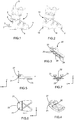
- FIGS 8 to 12 represent an alternative embodiment in which a metal reinforcement is added to the heel piece described above.
- this metal reinforcement is lightweight and small in size, for example in the form of a simple folded sheet of small thickness, is not comparable with the heavy and rigid structure of the Lowtech insert of the state of the art.
- the figure 9 describes more particularly a metal reinforcement 30 according to this embodiment variant.
- This reinforcement is a thin rounded blade, comprising a hook shape 32 at each of its two ends, and comprising an opening 31 at each of its two ends. These openings 31 are intended for positioning at the hollow fastening portions 21 of the heel.
- the rounded surface of the reinforcement has a shape corresponding to the rounded front wall of the heel, so that the reinforcement is positioned on this rounded front wall.
- the manufacturing method of this embodiment variant thus comprises a step of fixing the metal reinforcement 30.
- its two hooks 32 are inserted into slots formed by machining the heel and then the metal reinforcement is fixed by any means, in particular mechanical means such as screwing through at least one opening 31, 34 formed in the metal reinforcement 30.
- the manufacturing method of this embodiment variant comprises a preliminary step of positioning the metal reinforcement 30 in the injection mold before proceeding to the two overinjection stages, finally allowing to imprison the metal reinforcement 30 within the heel.
- the two hooks 32 of the ends of the reinforcement promote its grip in the surinjected plastic material.
- the metal reinforcement 30 is positioned so that the two openings 31 engage the reliefs intended to form the hollow fastening portions 21. This allows the precise positioning without difficulty of the metal reinforcement 30.
- another intermediate opening 34 which also facilitates the maintenance of the metal reinforcement 30 in the manufacturing mold.
- this metal reinforcement improves the rigidity and longevity of the heel, especially at the hollow fixing parts.
- the charged plastic material described above remains necessary and remains used in a zone similar to that described in the previous embodiment.
- the metal reinforcement performs a reinforcing function of the loaded plastic material, in particular at the friction surfaces of the hollow fixing parts.
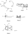
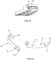
- FIGS. 13 and 14 represent a second embodiment of the heel 20, in which the reinforcement 30 is slightly modified at its two ends, which have openings 33 and no longer hook shapes. These openings 33 have the same function of ensuring the attachment of the reinforcements, either by screwing through these openings, or by the passage of the plastic material loaded through the openings 33 during overinjection, thus forming an anchoring means mechanical reinforcement 30.
- each annular reinforcement 30 is reduced and is in the simple form of two metal rings 35 disposed at the two hollow fastening portions 21 of the heel.
- each annular reinforcement comprises three arms 36 each having an opening 31, to form mechanical anchoring elements. Note, this form rings metal reinforcements allows them rotations when they are positioned in the mold without affecting the final result.
- FIGS 17 to 21 illustrate a rear heel 40 intended to be housed removably in a housing provided at the rear sole of the ski boot.
- This heel is also formed of a combination of a conventional plastic material with a loaded plastic material, manufactured by a double injection.
- the loaded plastic material performs the function of rigid reinforcement of the whole of the heel, and is in particular positioned in rigid areas 42 disposed at the vertical rear wall of the heel and at the level of the sole of the heel.
- Recesses are made in these rear rigid areas to form the elements of cooperation with a rear attachment device of a shoe on a ski touring. This rear heel is thus compliant with the Dynafit® standard.
- metal reinforcements 45 are inserted into these recesses, and fixed by screwing by screws 46. These reinforcements remain optional and alternatively could be removed.
- heelettes and removable relative to the rest of the shoe allows their replacement with other heelettes, either identical, in case of wear, or different, for example for another use of the same shoe. They may advantageously make it possible to form a shoe conforming to the ISO standard for ski touring boots, as previously illustrated.
- the Figures 22 to 25 illustrate for example a heel before practice of descent 50, which allows to form a ski boot format compatible with alpine ski boots as defined by the ISO 5355 standard.
- the front heel 50 is also formed by a double injection of which a plastic material loaded. The latter is at least used to form part of the front surface 54 of the heel which will form the sidewalk of the shoe on which the attachment jaws will engage, as well as to form a friction plate 55 under the lower surface, and more generally for an entire rigid zone 52.
- This heelette also comprises hollow fixing portions 51, compatible with the devices mount ski touring according to the Dynafit® standard, to also use such devices in the descent phase with a ski touring equipped with its traditional front fixing device.
- heelettes separate from the rest of the shoe are fixed to the shoe by any mechanical means, such as screws through through openings 26, 56 formed under the lower surface of the heel.
- the described heelettes use at least one filled plastic material.
- they may be formed integrally of the same charged plastic material in a single injection step.
- they can combine more than two materials.
- the loaded plastic material, and therefore the rigid zone can extend over the entire length of a heel, from its front end to its rear end.
- the invention also relates to a shoe equipped with several sets of removable heelettes of different geometries, but suitable for association with the incomplete sole of the rigid upper of the shoe.
- a ski boot formed by the use of a first set of removable sole can be transformed using a second set of removable sole so as to obtain a sole substantially compatible alternately with a use downhill and climbing, for the practice of ski touring, and / or to form an alpine ski boot.
- these heels will complete the rigid rod to form a shoe compatible with either the ISO standard of alpine skiing, or with the ISO standard of ski touring.
- a result obtained by this technical effect is to allow a compact footwear assembly whose use is provided for a transformation at each change up - down.
Description
La présente invention concerne une partie de chaussure de ski permettant la pratique du ski. Elle concerne aussi un ensemble chaussant du type chaussure de ski, adaptable par une transformation de sa semelle pour faciliter soit la montée, soit la descente, lors de la pratique du ski de randonnée, ou pour permettre la pratique du ski alpin. Elle concerne aussi une talonnette amovible en tant que telle pour chaussure de ski. Enfin, elle concerne un procédé de fabrication d'une partie de chaussure de ski, en particulier le ski de randonnée.The present invention relates to a ski boot part allowing the practice of skiing. It also relates to a footwear type ski boot, adaptable by a transformation of its sole to facilitate either the rise or the descent, during the practice of ski touring, or to allow the practice of downhill skiing. It also relates to a removable heel as such for ski boot. Finally, it relates to a method of manufacturing a portion of a ski boot, in particular ski touring.
Le document
Le document
D'autre part, il se pose toujours la question de faciliter et assurer la sécurité maximale de la phase de descente lors la pratique du ski de randonnée. La chaussure de ski alpin telle que normalisée est conçue de manière optimisée pour une telle descente, mais elle ne convient pas pour les phases de montée. Pour cela, le document
Un objet général de l'invention consiste à proposer une chaussure de ski, notamment adaptée au ski de randonnée, plus simple et moins chère que les solutions de l'état de la technique.A general object of the invention is to provide a ski boot, particularly adapted to ski touring, simpler and cheaper than the solutions of the state of the art.
Plus précisément, un objet de l'invention consiste donc à proposer une partie de chaussure destinée à former des moyens de coopération compatibles avec un dispositif de fixation de chaussure tel que décrit dans le document
L'invention repose sur un ensemble chaussant comprenant l'utilisation d'un matériau plastique chargé au niveau d'une zone de coopération avec un élément de maintien d'un dispositif de fixation de ski, en particulier au niveau des parties creuses formant les éléments de fixation de chaussure avec un dispositif de fixation d'un ski de randonnée selon le standard Dynafit®. L'objet de l'invention est plus précisément défini par les revendications. Ces objets, caractéristiques et avantages de la présente invention seront exposés en détail dans la description suivante de modes d'exécution particuliers faits à titre non-limitatif en relation avec les figures jointes parmi lesquelles :
- La
figure 1 représente une vue de côté d'une chaussure de ski conventionnelle selon l'état de la technique. - La
figure 2 représente une vue de côté d'une chaussure de ski de randonnée conventionnelle selon l'état de la technique. - Les
figures 3 et 4 représentent deux vues en perspective d'une talonnette avant selon un mode de réalisation de l'invention. - La
figure 5 représente une vue de côté de la talonnette avant selon le mode de réalisation de l'invention. - La
figure 6 représente une vue de dessous d'une coupe B-B de la talonnette avant selon le mode de réalisation de l'invention. - La
figure 7 représente une vue de l'avant d'une coupe A-A de la talonnette avant selon le mode de réalisation de l'invention. - La
figure 8 représente une vue en perspective d'une talonnette avant selon une première variante du mode de réalisation de l'invention. - La
figure 9 représente une vue en perspective d'un renfort métallique à intégrer dans la talonnette avant selon la première variante du mode de réalisation de l'invention. - La
figure 10 représente une vue de côté de la talonnette avant selon la première variante du mode de réalisation de l'invention. - La
figure 11 représente une vue de dessous d'une coupe B-B de la talonnette avant selon la première variante du mode de réalisation de l'invention. - La
figure 12 représente une vue de l'avant d'une coupe A-A de la talonnette avant selon la première variante du mode de réalisation de l'invention. - La
figure 13 représente une vue en perspective d'une talonnette avant selon une seconde variante du mode de réalisation de l'invention. - La
figure 14 représente une vue en perspective d'un renfort métallique à intégrer dans la talonnette avant selon la seconde variante du mode de réalisation de l'invention. - La
figure 15 représente une vue en perspective d'une talonnette avant selon une troisième variante du mode de réalisation de l'invention. - La
figure 16 représente une vue en perspective d'un renfort métallique à intégrer dans la talonnette avant selon la troisième variante du mode de réalisation de l'invention. - La
figure 17 représente une vue en perspective d'une talonnette arrière selon un mode de réalisation de l'invention. - La
figure 18 représente une vue en perspective d'un renfort pour talonnette arrière selon un mode de réalisation de l'invention. - La
figure 19 représente une vue de côté d'une talonnette arrière selon un mode de réalisation de l'invention. - La
figure 20 représente une vue de l'arrière de la talonnette arrière selon un mode de réalisation de l'invention. - La
figure 21 représente une vue de côté d'une coupe A-A de la talonnette arrière selon le mode de réalisation de l'invention. - La
figure 22 représente une vue en perspective d'une talonnette avant pour la pratique du ski en descente selon un mode de réalisation de l'invention. - La
figure 23 représente une vue de côté de la talonnette avant pour la pratique du ski en descente selon le mode de réalisation de l'invention. - La
figure 24 représente une vue de dessous d'une coupe B-B de la talonnette avant pour la pratique du ski en descente selon le mode de réalisation de l'invention. - La
figure 25 représente une vue de l'avant d'une coupe A-A de la talonnette avant pour la pratique du ski en descente selon le mode de réalisation de l'invention.
- The
figure 1 represents a side view of a conventional ski boot according to the state of the art. - The
figure 2 represents a side view of a conventional touring ski boot according to the state of the art. - The
Figures 3 and 4 represent two perspective views of a front heel according to an embodiment of the invention. - The
figure 5 represents a side view of the front heel according to the embodiment of the invention. - The
figure 6 represents a bottom view of a section BB of the front heel according to the embodiment of the invention. - The
figure 7 represents a front view of a section AA of the front heel according to the embodiment of the invention. - The
figure 8 represents a perspective view of a front heel piece according to a first variant of the embodiment of the invention. - The
figure 9 represents a perspective view of a metal reinforcement to be integrated in the front heel piece according to the first variant of the embodiment of the invention. - The
figure 10 represents a side view of the front heel according to the first variant of the embodiment of the invention. - The
figure 11 represents a bottom view of a section BB of the front heel according to the first variant of the embodiment of the invention. - The
figure 12 represents a front view of a section AA of the front heel according to the first variant of the embodiment of the invention. - The
figure 13 represents a perspective view of a front heel piece according to a second variant of the embodiment of the invention. - The
figure 14 is a perspective view of a metal reinforcement to be integrated in the front heel according to the second variant of the embodiment of the invention. - The
figure 15 is a perspective view of a front heel according to a third variant of the embodiment of the invention. - The
figure 16 is a perspective view of a metal reinforcement to be integrated in the front heel according to the third variant of the embodiment of the invention. - The
figure 17 represents a perspective view of a rear heel piece according to one embodiment of the invention. - The
figure 18 represents a perspective view of a back heel reinforcement according to one embodiment of the invention. - The
figure 19 represents a side view of a rear heel piece according to one embodiment of the invention. - The
figure 20 represents a rear view of the rear heel piece according to one embodiment of the invention. - The
figure 21 represents a side view of a section AA of the rear heel piece according to the embodiment of the invention. - The
figure 22 represents a perspective view of a front heel for downhill skiing according to one embodiment of the invention. - The
figure 23 represents a side view of the front heel for downhill skiing according to the embodiment of the invention. - The
figure 24 represents a bottom view of a section BB of the front heel for downhill skiing according to the embodiment of the invention. - The
figure 25 represents a front view of a section AA of the front heel for downhill skiing according to the embodiment of the invention.
Dans la description suivante, nous utiliserons la direction longitudinale x pour la direction horizontale orientée de l'arrière vers l'avant par rapport à la chaussure, la direction transversale y pour la direction horizontale perpendiculaire, et la direction verticale z perpendiculaire aux deux précédentes, orientée vers le haut de la chaussure. D'autre part, les mêmes références seront utilisées pour les différentes variantes de réalisation pour désigner des mêmes caractéristiques.In the following description, we will use the longitudinal direction x for the horizontal direction oriented from back to front with respect to the shoe, the transverse direction y for the perpendicular horizontal direction, and the vertical direction z perpendicular to the two preceding ones, oriented towards the top of the shoe. On the other hand, the same references will be used for the different embodiments to designate the same characteristics.
La
La
Selon un premier aspect des variantes de réalisation de l'invention qui vont être décrites par la suite, de manière non limitative, la chaussure de ski comprend une semelle incomplète, formant des logements pour recevoir une talonnette avant 20 et une talonnette arrière 40. Ces talonnettes permettent à la même tige de chaussure de devenir compatible pour plusieurs utilisations différentes, et en particulier de se conformer aux deux normes ISO 5355 et 9523, respectivement de ski alpin et de ski de randonnée.According to a first aspect of the embodiments of the invention which will be described later, without limitation, the ski boot comprises an incomplete sole, forming housings for receiving a
Les
Cette approche présente ainsi l'avantage de permettre de fabriquer la talonnette avant 20 par simple injection plastique, selon des procédés de fabrication habituels, sans l'inconvénient du positionnement d'un insert Lowtech de l'état de la technique. De plus, le résultat est un allègement de la chaussure et une diminution de son coût.This approach thus has the advantage of making it possible to manufacture the
Le matériau plastique chargé peut être formé par le mélange d'un polymère thermoplastique, comme du polyuréthane ou du polyamide, et d'un additif à base de matériau rigide, comme du carbone ou de l'aramide, pour former un produit mixte utilisable par injection comme un matériau plastique conventionnel mais permettant d'atteindre une rigidité nettement supérieure. Ainsi, l'additif (ou charge) comprend des fibres courtes ou longues, compatibles avec un procédé d'injection plastique, comme des fibres de carbone ou de verre. Une fibre courte a un ratio de la longueur de la fibre par rapport à son diamètre compris entre 20 et 60. La longueur des fibres courtes est inférieure à 12 mm. Une fibre longue a un ratio de la longueur de la fibre par rapport au diamètre compris entre 200 et 500. La longueur des fibres longues est supérieure à 12 mm. A titre d'exemple, une talonnette comprenant un matériau plastique chargé entre 30% et 50% peut permettre d'atteindre un module de Young compris entre 1600 MPa et 32000 MPa. De préférence, les fibres de renfort seront choisies, par leur quantité et leurs propriétés mécaniques, pour atteindre un matériau chargé final dont le module de Young est supérieur ou égal à 20000 MPa. A titre d'exemple, une talonnette comprenant un polyuréthane chargé avec 30% de fibres courtes de carbone permet d'atteindre un module de Young compris autour de 13700 MPa. Une talonnette comprenant un polyamide-6,6 chargé avec 50% de fibres courtes de carbone permet d'atteindre un module de Young compris autour de 30700 MPa. Une talonnette comprenant un polypropylène chargé avec 30% de fibres longues de verre permet d'atteindre un module de Young compris autour de 5500 MPa.The filled plastic material may be formed by mixing a thermoplastic polymer, such as polyurethane or polyamide, and an additive based on rigid material, such as carbon or aramid, to form a mixed product usable by injection as a conventional plastic material but to achieve a significantly higher rigidity. Thus, the additive (or filler) comprises short or long fibers compatible with a plastic injection process, such as carbon or glass fibers. A short fiber has a ratio of the length of the fiber to its diameter of between 20 and 60. The length of the short fibers is less than 12 mm. A long fiber has a ratio of the length of the fiber to the diameter of between 200 and 500. The length of the long fibers is greater than 12 mm. For example, a heel comprising a plastic material loaded between 30% and 50% can achieve a Young's modulus between 1600 MPa and 32000 MPa. Preferably, the reinforcing fibers will be chosen, by their quantity and their mechanical properties, to reach a final loaded material whose Young's modulus is greater than or equal to 20000 MPa. For example, a heel comprising a polyurethane loaded with 30% short carbon fibers achieves a Young's modulus of around 13700 MPa. A heel pad comprising a polyamide-6,6 loaded with 50% short carbon fibers makes it possible to reach a Young's modulus of around 30700 MPa. A heel pad comprising a polypropylene loaded with 30% long glass fibers makes it possible to reach a Young's modulus of around 5500 MPa.
Comme cela apparaît sur les vues en coupe des
D'autre part, il n'est pas nécessaire d'utiliser ce matériau plastique chargé pour l'ensemble de la talonnette. Selon une utilisation minimale, le matériau plastique chargé est uniquement disposé au niveau des parties creuses de fixation 21. Selon le mode de réalisation, la talonnette comprend l'association du matériau plastique chargé avec un matériau plastique conventionnel, par exemple un polyuréthane, ou un matériau plastique conventionnel plus souple, comme un polyéthylène ou un caoutchouc, non chargé.On the other hand, it is not necessary to use this loaded plastic material for the whole of the heel. According to a minimal use, the loaded plastic material is only disposed at the
Pour cela, la talonnette est complétée par une seconde étape d'injection à l'aide d'un simple matériau plastique, non chargé, pour obtenir une talonnette qui s'étend finalement de préférence sur au moins un quart de la longueur de la chaussure, dans la direction longitudinale x, et sur une hauteur permettant d'intégrer une partie frontale 27, qui formera l'intégralité du trottoir antérieur de la chaussure, et les parties creuses de fixation 21. Le matériau plastique non chargé est réparti avantageusement sur des zones souples 23, notamment au niveau de la semelle.For this, the heel is completed by a second injection step with a simple plastic material, not loaded, to obtain a heel which ultimately ultimately extends over at least a quarter of the length of the shoe , in the longitudinal direction x, and on a height for integrating a
Comme cela a été évoqué ci-dessus, l'invention porte aussi sur un procédé de fabrication d'une talonnette, qui comprend une étape d'injection d'un matériau plastique chargé dans un moule, ce dernier comprenant les reliefs formant des parties mâles correspondant aux futures parties creuses à fabriquer. Ensuite, une seconde injection d'un matériau plastique non chargé est prévu selon ce mode de réalisation.As has been mentioned above, the invention also relates to a method of manufacturing a heel, which comprises a step of injecting a plastic material loaded into a mold, the latter comprising the reliefs forming male parts corresponding to future hollow parts to be manufactured. Then, a second injection of an unfilled plastic material is provided according to this embodiment.
Les
La
Le procédé de fabrication de cette variante de réalisation comprend donc une étape de fixation du renfort métallique 30. Pour cela, ses deux crochets 32 sont insérés dans des fentes formées par un usinage de la talonnette, puis le renfort métallique est fixé par tout moyen, notamment un moyen mécanique comme un vissage au travers d'au moins une ouverture 31, 34 formée dans le renfort métallique 30.The manufacturing method of this embodiment variant thus comprises a step of fixing the
En variante, le procédé de fabrication de cette variante de réalisation comprend une étape préalable consistant à positionner le renfort métallique 30 dans le moule d'injection avant de procéder aux deux étapes de surinjection, permettant finalement d'emprisonner le renfort métallique 30 au sein de la talonnette. Les deux crochets 32 des extrémités du renfort favorisent son emprise dans le matériau plastique surinjecté. Dans le moule, le renfort métallique 30 est positionné de sorte que les deux ouvertures 31 viennent en prise avec les reliefs destinés à former les parties creuses de fixation 21. Cela permet le positionnement précis sans difficulté du renfort métallique 30. Il comprend de plus une autre ouverture 34 intermédiaire, qui facilite aussi le maintien du renfort métallique 30 dans le moule de fabrication.Alternatively, the manufacturing method of this embodiment variant comprises a preliminary step of positioning the
Finalement, ce renfort métallique permet d'améliorer la rigidité et la longévité de la talonnette, notamment au niveau des parties creuses de fixation. Dans cette solution, le matériau plastique chargé décrit précédemment reste nécessaire et reste utilisé dans une zone similaire à celle décrite dans le mode de réalisation précédent. Le renfort métallique remplit une fonction de renfort du matériau plastique chargé, notamment au niveau des surfaces de frottement des parties creuses de fixation.Finally, this metal reinforcement improves the rigidity and longevity of the heel, especially at the hollow fixing parts. In this solution, the charged plastic material described above remains necessary and remains used in a zone similar to that described in the previous embodiment. The metal reinforcement performs a reinforcing function of the loaded plastic material, in particular at the friction surfaces of the hollow fixing parts.
Les
Les
Les
Le mode de réalisation choisi avec des talonnettes distinctes et amovibles par rapport au reste de la chaussure permet leur remplacement avec d'autres talonnettes, soit identiques, en cas d'usure, soit différentes, par exemple pour une autre utilisation de la même chaussure. Elles peuvent notamment avantageusement permettre de former une chaussure conforme à la norme ISO des chaussures de ski de randonnée, comme illustré précédemment.The embodiment chosen with separate heelettes and removable relative to the rest of the shoe allows their replacement with other heelettes, either identical, in case of wear, or different, for example for another use of the same shoe. They may advantageously make it possible to form a shoe conforming to the ISO standard for ski touring boots, as previously illustrated.
Les
Dans tous les cas, les talonnettes distinctes du reste de la chaussure sont fixées sur la chaussure par tout moyen mécanique, comme par des vis au travers d'ouvertures 26, 56 traversantes pratiquées sous la surface inférieure de la talonnette.In all cases, heelettes separate from the rest of the shoe are fixed to the shoe by any mechanical means, such as screws through through
Les talonnettes décrites utilisent au moins un matériau plastique chargé. En variante, elles peuvent être formées intégralement du même matériau plastique chargé, en une seule étape d'injection. Selon une autre variante, elles peuvent combiner plus de deux matériaux. Selon une autre variante, le matériau plastique chargé, et donc la zone rigide, peut s'étendre sur toute la longueur d'une talonnette, de son extrémité avant à son extrémité arrière.The described heelettes use at least one filled plastic material. Alternatively, they may be formed integrally of the same charged plastic material in a single injection step. According to another variant, they can combine more than two materials. According to another variant, the loaded plastic material, and therefore the rigid zone, can extend over the entire length of a heel, from its front end to its rear end.
Finalement, la solution atteint ainsi bien les objets recherchés et présente les avantages suivants :
- les parties creuses de fixation sont obtenues directement par moulage, ce qui permet d'éviter le coût induit par l'insert Lowtech métallique de l'état de la technique ;
- le procédé est aussi simplifié puisqu'on évite l'étape délicate de positionnement de l'insert Lowtech dans le moule avant la surinjection ;
- le procédé est aussi simplifié puisqu'on évite l'étape délicate de fixation de l'insert Lowtech en l'entourant avec suffisamment de matériau plastique pour bien le solidariser ;
- les moules de fabrication sont simplifiés car il n'y a pas de logement d'insert durant l'injection ou simplement des renforts discrets et peu problématiques ;
- si une talonnette est défectueuse, elle peut être regranulée et recyclée plus facilement car il n'y a pas d'insert Lowtech à retirer ;
- la chaussure de l'invention est plus légère car il n y a pas le poids de l'insert Lowtech.
- the hollow fixing parts are obtained directly by molding, which makes it possible to avoid the cost induced by the metal Lowtech insert of the state of the art;
- the method is also simplified since it avoids the delicate step of positioning the Lowtech insert in the mold before overinjection;
- the method is also simplified since it avoids the tricky step of fixing the Lowtech insert by surrounding it with enough plastic material to secure it well;
- manufacturing molds are simplified because there is no insert housing during injection or simply discreet reinforcements and little problem;
- if a heel is defective, it can be regranulated and recycled more easily because there is no Lowtech insert to remove;
- the boot of the invention is lighter because it does not have the weight of the Lowtech insert.
L'invention porte aussi sur une chaussure équipée de plusieurs ensembles de talonnettes amovibles de géométries différentes, mais aptes à une association avec la semelle incomplète de la tige rigide de la chaussure. Ainsi, une chaussure de ski formée par l'utilisation d'un premier ensemble de semelle amovible peut être transformée à l'aide d'un second ensemble de semelle amovible de manière à obtenir une semelle sensiblement compatible alternativement avec une utilisation en descente et en montée, pour la pratique du ski de randonnée, et/ou pour former une chaussure de ski alpin. Avantageusement, ces talonnettes permettront de compléter la tige rigide pour former une chaussure compatible soit avec la norme ISO du ski alpin, soit avec la norme ISO du ski de randonnée.The invention also relates to a shoe equipped with several sets of removable heelettes of different geometries, but suitable for association with the incomplete sole of the rigid upper of the shoe. Thus, a ski boot formed by the use of a first set of removable sole can be transformed using a second set of removable sole so as to obtain a sole substantially compatible alternately with a use downhill and climbing, for the practice of ski touring, and / or to form an alpine ski boot. Advantageously, these heels will complete the rigid rod to form a shoe compatible with either the ISO standard of alpine skiing, or with the ISO standard of ski touring.
Un résultat obtenu par cet effet technique est de permettre d'avoir un ensemble chaussant peu encombrant dont l'utilisation est prévue pour une transformation à chaque changement montée - descente.A result obtained by this technical effect is to allow a compact footwear assembly whose use is provided for a transformation at each change up - down.
Les modes de réalisation précédents ont été décrits pour former des talonnettes amovibles de chaussures de ski. Selon un autre mode de réalisation, le même concept pourrait être exploité pour fabriquer d'autres parties de chaussures, voire l'intégralité d'une coque ou d'une tige de chaussure, dans laquelle la partie avant et/ou arrière de la semelle d'une chaussure de ski ne serait pas amovible, formerait un tout monolithique, non distinct du reste de la chaussure ou de la coque, voire d'une sous partie de la coque. En effet, ce concept de l'invention peut être étendu pour former toute zone de coopération d'une chaussure de ski avec un élément de maintien d'un dispositif de fixation de la chaussure sur un ski, à partir d'un matériau plastique chargé. Dans une telle approche d'une chaussure ou coque monobloc, le matériau plastique chargé pourrait aussi s'étendre dans d'autres zones que celles prévues pour les zones de coopération de la chaussure avec le dispositif de fixation d'un ski, pour former des renforts par exemple.The previous embodiments have been described to form removable heel ski boots. According to another embodiment, the same concept could be exploited to manufacture other shoe parts, or even the entirety of a shell or a shoe upper, in which the front and / or rear part of the sole a Ski boot would not be removable, would form a monolithic whole, not distinct from the rest of the shoe or the hull, or even a sub part of the hull. Indeed, this concept of the invention can be extended to form any zone of cooperation of a ski boot with a holding element of a device for fixing the boot on a ski, from a plastic material loaded . In such an approach to a shoe or one-piece shell, the loaded plastic material could also extend into other areas than those provided for the zones of cooperation of the shoe with the ski binding device, to form reinforcements for example.
Claims (14)
- Sole pad for a ski boot, comprising at least one engagement zone suitable for engagement with a holding element of a ski binding device, characterized in that the engagement zone comprises a zone (22; 42; 52) made of plastic material filled with short fibres and obtained by injection, and in that the ski boot sole pad comprises at least one zone made of non-filled plastic material, and characterized in that:- the boot sole pad is a removable front sole pad which comprises two hollow attachment portions (21) that are arranged laterally close to the front end of the ski boot sole pad and are designed to engage with two lateral clamping portions of a device for attaching a ski boot to a touring ski, the ski boot sole pad comprising at least one zone (22) made of plastic material filled with short fibres at the two hollow attachment portions (21), these being in particular created within a zone (22) made of filled plastic material; or- the ski boot sole pad is a removable rear sole pad which comprises a plastic material filled with short fibres positioned at least in rigid zones (42) that are arranged at the vertical rear wall and at the sole in the rear portion of the boot sole pad, and in which cutouts are created in these rear rigid zones to form the elements for engaging with a rear ski binding for a ski boot on a touring ski.
- Sole pad for a ski boot according to the preceding claim, characterized in that it comprises a zone (22) made of filled plastic material extending from one hollow attachment portion (21) to the other in the transverse direction of the ski boot sole pad, and/or extending as far as the front end of the ski boot sole pad.
- Sole pad for a ski boot according to one of the preceding claims, characterized in that it comprises a rigid zone made of filled material extending over its entire length.
- Sole pad for a ski boot according to one of the preceding claims, characterized in that it comprises a metal reinforcement (30; 45) at an engagement zone, in particular of two hollow attachment portions (21).
- Sole pad for a ski boot according to the preceding claim, characterized in that the metal reinforcement (30) comprises two metal rings (35), and/or in that it extends continuously from one hollow attachment portion (21) to another following essentially the frontal surface of the ski boot sole pad, and/or in that it is in the form of bent sheet metal.
- Sole pad for a ski boot according to Claim 4 or 5, characterized in that the metal reinforcement (30) comprises an opening (31) at the level of hollow attachment portions (21).
- Sole pad for a ski boot according to one of the preceding claims, characterized in that the filled plastic material is injection-moulded and comprises fibres such as carbon fibres or glass fibres.
- Ski boot, characterized in that it comprises a sole pad for a ski boot according to one of the preceding claims, forming at least part of its sole.
- Ski boot according to the preceding claim, characterized in that the ski boot sole pad is distinct from the rest of the boot and is removably attached to the rest of the boot.
- Ski boot according to the preceding claim, characterized in that the ski boot sole pad is a front sole pad (20) which comprises two hollow attachment portions (21) and/or a rear sole pad (40) which comprises at least one cutout forming an engagement element for engagement with a holding element of a device for attaching the boot to a ski.
- Footwear assembly comprising a rigid upper of the ski boot type provided with an incomplete sole and comprising at least one ski boot sole pad according to one of Claims 1 to 7, and characterized in that it comprises:- at least one first removable sole pad which comprises a frontal surface (54) and a bearing plate (55) and which is able to complete the incomplete sole of the upper in order to form a boot with a sole that is suitable for engaging in alpine skiing,- at least one second removable sole pad, which is different from the first and is able to complete the incomplete sole of the upper in order to form a boot that is suitable for engaging in ski touring.
- Method for producing a ski boot sole pad according to one of Claims 1 to 7, characterized in that it comprises a step of injecting a filled plastic material into a mould so as to form at least one engagement zone of the ski boot sole pad that is suitable for engagement with a holding element of a device for attaching a boot to a ski, in particular a mould comprising two reliefs that are able to form two hollow portions (21) for attaching the ski boot sole pad.
- Ski boot sole pad production method according to the preceding claim, characterized in that it comprises a step of positioning at least one metal reinforcement at the level of two reliefs of the mould, such as a metal ring, prior to injection of the filled plastic material.
- Ski boot sole pad production method according to Claim 12 or 13, characterized in that it comprises another step of injecting a non-filled plastic material.
Priority Applications (1)
| Application Number | Priority Date | Filing Date | Title |
|---|---|---|---|
| EP13425107.3A EP2829188B1 (en) | 2013-07-25 | 2013-07-25 | Ski boot |
Applications Claiming Priority (1)
| Application Number | Priority Date | Filing Date | Title |
|---|---|---|---|
| EP13425107.3A EP2829188B1 (en) | 2013-07-25 | 2013-07-25 | Ski boot |
Publications (2)
| Publication Number | Publication Date |
|---|---|
| EP2829188A1 EP2829188A1 (en) | 2015-01-28 |
| EP2829188B1 true EP2829188B1 (en) | 2018-05-09 |
Family
ID=49226107
Family Applications (1)
| Application Number | Title | Priority Date | Filing Date |
|---|---|---|---|
| EP13425107.3A Active EP2829188B1 (en) | 2013-07-25 | 2013-07-25 | Ski boot |
Country Status (1)
| Country | Link |
|---|---|
| EP (1) | EP2829188B1 (en) |
Cited By (1)
| Publication number | Priority date | Publication date | Assignee | Title |
|---|---|---|---|---|
| US20230069114A1 (en) * | 2021-08-30 | 2023-03-02 | DaleBoot Holdings LLC | Ski boot having cantable sole |
Families Citing this family (1)
| Publication number | Priority date | Publication date | Assignee | Title |
|---|---|---|---|---|
| EP3375312B1 (en) * | 2017-03-17 | 2020-11-04 | MARKER Deutschland GmbH | Children's ski boot with improved walking function |
Family Cites Families (11)
| Publication number | Priority date | Publication date | Assignee | Title |
|---|---|---|---|---|
| AT381458B (en) | 1985-03-25 | 1986-10-27 | Barthel Fritz | TOURING SKI BINDING |
| FR2766065A1 (en) * | 1997-07-16 | 1999-01-22 | Salomon Sa | In=line roller skate with moulded boot |
| CH695307A5 (en) * | 2001-09-21 | 2006-03-31 | Lange Int Sa | Alpine ski boot. |
| AT413316B (en) | 2004-01-28 | 2006-02-15 | Barthel Fritz | STORAGE PLATE AND TOUR KINDER FOR A TOURING KIBING SYSTEM |
| EP1642706B1 (en) * | 2004-09-29 | 2006-11-15 | Lange International S.A. | Very hard material sports boot |
| ITVE20060010U1 (en) * | 2006-03-03 | 2007-09-04 | Ober Alp Spa | PERFECT FOOTWEAR FOR ALPINE SKIING.- |
| ITVE20070024U1 (en) | 2007-07-05 | 2009-01-06 | Ober Alp Spa | PERFECT SKI SHOE |
| FR2928523B1 (en) * | 2008-03-12 | 2015-03-06 | Eurl Gignoux | SKI OR MOUNTAIN SHOE IN COMPOSITE MATERIALS |
| FR2945185B1 (en) * | 2009-05-05 | 2011-10-07 | Gignoux Sarl | SKI FIXING DEVICE FOR HIKING |
| DE102010039475B4 (en) * | 2010-08-18 | 2022-01-20 | Salewa Sport Ag | Coupling element for a ski boot and ski boot |
| FR2971675B1 (en) * | 2011-02-21 | 2014-10-10 | Eurl Gignoux | FLEXIBLE SHOE SHELL AT THE METATARSO-PHALANGIAN JOINT |
-
2013
- 2013-07-25 EP EP13425107.3A patent/EP2829188B1/en active Active
Non-Patent Citations (1)
| Title |
|---|
| None * |
Cited By (1)
| Publication number | Priority date | Publication date | Assignee | Title |
|---|---|---|---|---|
| US20230069114A1 (en) * | 2021-08-30 | 2023-03-02 | DaleBoot Holdings LLC | Ski boot having cantable sole |
Also Published As
| Publication number | Publication date |
|---|---|
| EP2829188A1 (en) | 2015-01-28 |
Similar Documents
| Publication | Publication Date | Title |
|---|---|---|
| EP1842442B1 (en) | Sole for cross-country ski boots comprising improved means of fixing a binding and boot equipped with such a sole | |
| CA1136850A (en) | Method for the manufacture of a sports shoe, and shoe made by said method | |
| EP2762023B1 (en) | Footwear including a first footwear element and a second footwear element | |
| EP1568585A1 (en) | Device for quick mounting and release of a cycling footwear on an automatic pedal of a cycle | |
| EP3195748B1 (en) | Sole of footwear for cross-country skiing | |
| EP2580978A1 (en) | Schuh mit verbesserter Einspannmöglichkeit des Schafts | |
| EP2572599B1 (en) | Shell of a ski boot with spoiler | |
| EP1935460A1 (en) | Article comprising a link for holding or tightening a foot or a shoe | |
| EP2829188B1 (en) | Ski boot | |
| EP2829187B1 (en) | Ski boot | |
| EP2984957A1 (en) | Sports shoe | |
| FR2793156A1 (en) | DEVICE FOR RETAINING A SHOE ON A SNOWBOARD | |
| EP2305055B1 (en) | Series of ski boots with one ski boot at least containing a clog | |
| EP3673761B1 (en) | Cross-country ski boot element obtained by co-injection | |
| FR2674107A1 (en) | ALPINE SKI SHOE WITH ENERGY COMPONENT JOINED ON HULL. | |
| EP3123884B1 (en) | Shoe sole for gliding sports | |
| FR2624355A1 (en) | Monoblock piece intended for making up a shoe | |
| EP0785002B1 (en) | Binding element assembly for boots on skis | |
| FR2701361A1 (en) | Lever-rack closure device for a ski boot | |
| EP0436444B1 (en) | Plastic ski boot | |
| FR3044525B1 (en) | TONGUE FOR FOOTWEAR SHOE INTERIOR | |
| FR2774605A1 (en) | METHOD FOR MANUFACTURING A RIGID STRUCTURAL ELEMENT OF A SPORTS ARTICLE | |
| EP3170417B1 (en) | Shell bottom for a ski boot and ski boot including such a shell bottom | |
| FR3136681A1 (en) | Core for ski and ski including such a core | |
| EP2989917B1 (en) | Sports shoe |
Legal Events
| Date | Code | Title | Description |
|---|---|---|---|
| 17P | Request for examination filed |
Effective date: 20130725 |
|
| AK | Designated contracting states |
Kind code of ref document: A1 Designated state(s): AL AT BE BG CH CY CZ DE DK EE ES FI FR GB GR HR HU IE IS IT LI LT LU LV MC MK MT NL NO PL PT RO RS SE SI SK SM TR |
|
| AX | Request for extension of the european patent |
Extension state: BA ME |
|
| PUAI | Public reference made under article 153(3) epc to a published international application that has entered the european phase |
Free format text: ORIGINAL CODE: 0009012 |
|
| R17P | Request for examination filed (corrected) |
Effective date: 20150728 |
|
| RBV | Designated contracting states (corrected) |
Designated state(s): AL AT BE BG CH CY CZ DE DK EE ES FI FR GB GR HR HU IE IS IT LI LT LU LV MC MK MT NL NO PL PT RO RS SE SI SK SM TR |
|
| 17Q | First examination report despatched |
Effective date: 20170317 |
|
| GRAP | Despatch of communication of intention to grant a patent |
Free format text: ORIGINAL CODE: EPIDOSNIGR1 |
|
| INTG | Intention to grant announced |
Effective date: 20171124 |
|
| RIN1 | Information on inventor provided before grant (corrected) |
Inventor name: FREGONI, ANDREA Inventor name: POSATO, TIZIANO Inventor name: PUGET, NICOLAS |
|
| GRAS | Grant fee paid |
Free format text: ORIGINAL CODE: EPIDOSNIGR3 |
|
| GRAA | (expected) grant |
Free format text: ORIGINAL CODE: 0009210 |
|
| AK | Designated contracting states |
Kind code of ref document: B1 Designated state(s): AL AT BE BG CH CY CZ DE DK EE ES FI FR GB GR HR HU IE IS IT LI LT LU LV MC MK MT NL NO PL PT RO RS SE SI SK SM TR |
|
| REG | Reference to a national code |
Ref country code: GB Ref legal event code: FG4D Free format text: NOT ENGLISH |
|
| REG | Reference to a national code |
Ref country code: CH Ref legal event code: EP Ref country code: AT Ref legal event code: REF Ref document number: 996703 Country of ref document: AT Kind code of ref document: T Effective date: 20180515 |
|
| REG | Reference to a national code |
Ref country code: DE Ref legal event code: R096 Ref document number: 602013037170 Country of ref document: DE Ref country code: IE Ref legal event code: FG4D Free format text: LANGUAGE OF EP DOCUMENT: FRENCH |
|
| REG | Reference to a national code |
Ref country code: DE Ref legal event code: R096 Ref document number: 602013037170 Country of ref document: DE |
|
| REG | Reference to a national code |
Ref country code: FR Ref legal event code: PLFP Year of fee payment: 6 |
|
| REG | Reference to a national code |
Ref country code: NL Ref legal event code: MP Effective date: 20180509 |
|
| REG | Reference to a national code |
Ref country code: LT Ref legal event code: MG4D |
|
| PG25 | Lapsed in a contracting state [announced via postgrant information from national office to epo] |
Ref country code: SE Free format text: LAPSE BECAUSE OF FAILURE TO SUBMIT A TRANSLATION OF THE DESCRIPTION OR TO PAY THE FEE WITHIN THE PRESCRIBED TIME-LIMIT Effective date: 20180509 Ref country code: LT Free format text: LAPSE BECAUSE OF FAILURE TO SUBMIT A TRANSLATION OF THE DESCRIPTION OR TO PAY THE FEE WITHIN THE PRESCRIBED TIME-LIMIT Effective date: 20180509 Ref country code: ES Free format text: LAPSE BECAUSE OF FAILURE TO SUBMIT A TRANSLATION OF THE DESCRIPTION OR TO PAY THE FEE WITHIN THE PRESCRIBED TIME-LIMIT Effective date: 20180509 Ref country code: BG Free format text: LAPSE BECAUSE OF FAILURE TO SUBMIT A TRANSLATION OF THE DESCRIPTION OR TO PAY THE FEE WITHIN THE PRESCRIBED TIME-LIMIT Effective date: 20180809 Ref country code: FI Free format text: LAPSE BECAUSE OF FAILURE TO SUBMIT A TRANSLATION OF THE DESCRIPTION OR TO PAY THE FEE WITHIN THE PRESCRIBED TIME-LIMIT Effective date: 20180509 Ref country code: NO Free format text: LAPSE BECAUSE OF FAILURE TO SUBMIT A TRANSLATION OF THE DESCRIPTION OR TO PAY THE FEE WITHIN THE PRESCRIBED TIME-LIMIT Effective date: 20180809 |
|
| PGFP | Annual fee paid to national office [announced via postgrant information from national office to epo] |
Ref country code: DE Payment date: 20180710 Year of fee payment: 6 |
|
| PG25 | Lapsed in a contracting state [announced via postgrant information from national office to epo] |
Ref country code: GR Free format text: LAPSE BECAUSE OF FAILURE TO SUBMIT A TRANSLATION OF THE DESCRIPTION OR TO PAY THE FEE WITHIN THE PRESCRIBED TIME-LIMIT Effective date: 20180810 Ref country code: NL Free format text: LAPSE BECAUSE OF FAILURE TO SUBMIT A TRANSLATION OF THE DESCRIPTION OR TO PAY THE FEE WITHIN THE PRESCRIBED TIME-LIMIT Effective date: 20180509 Ref country code: RS Free format text: LAPSE BECAUSE OF FAILURE TO SUBMIT A TRANSLATION OF THE DESCRIPTION OR TO PAY THE FEE WITHIN THE PRESCRIBED TIME-LIMIT Effective date: 20180509 Ref country code: LV Free format text: LAPSE BECAUSE OF FAILURE TO SUBMIT A TRANSLATION OF THE DESCRIPTION OR TO PAY THE FEE WITHIN THE PRESCRIBED TIME-LIMIT Effective date: 20180509 Ref country code: HR Free format text: LAPSE BECAUSE OF FAILURE TO SUBMIT A TRANSLATION OF THE DESCRIPTION OR TO PAY THE FEE WITHIN THE PRESCRIBED TIME-LIMIT Effective date: 20180509 |
|
| REG | Reference to a national code |
Ref country code: AT Ref legal event code: MK05 Ref document number: 996703 Country of ref document: AT Kind code of ref document: T Effective date: 20180509 |
|
| PG25 | Lapsed in a contracting state [announced via postgrant information from national office to epo] |
Ref country code: CZ Free format text: LAPSE BECAUSE OF FAILURE TO SUBMIT A TRANSLATION OF THE DESCRIPTION OR TO PAY THE FEE WITHIN THE PRESCRIBED TIME-LIMIT Effective date: 20180509 Ref country code: SK Free format text: LAPSE BECAUSE OF FAILURE TO SUBMIT A TRANSLATION OF THE DESCRIPTION OR TO PAY THE FEE WITHIN THE PRESCRIBED TIME-LIMIT Effective date: 20180509 Ref country code: PL Free format text: LAPSE BECAUSE OF FAILURE TO SUBMIT A TRANSLATION OF THE DESCRIPTION OR TO PAY THE FEE WITHIN THE PRESCRIBED TIME-LIMIT Effective date: 20180509 Ref country code: RO Free format text: LAPSE BECAUSE OF FAILURE TO SUBMIT A TRANSLATION OF THE DESCRIPTION OR TO PAY THE FEE WITHIN THE PRESCRIBED TIME-LIMIT Effective date: 20180509 Ref country code: DK Free format text: LAPSE BECAUSE OF FAILURE TO SUBMIT A TRANSLATION OF THE DESCRIPTION OR TO PAY THE FEE WITHIN THE PRESCRIBED TIME-LIMIT Effective date: 20180509 Ref country code: EE Free format text: LAPSE BECAUSE OF FAILURE TO SUBMIT A TRANSLATION OF THE DESCRIPTION OR TO PAY THE FEE WITHIN THE PRESCRIBED TIME-LIMIT Effective date: 20180509 Ref country code: AT Free format text: LAPSE BECAUSE OF FAILURE TO SUBMIT A TRANSLATION OF THE DESCRIPTION OR TO PAY THE FEE WITHIN THE PRESCRIBED TIME-LIMIT Effective date: 20180509 |
|
| REG | Reference to a national code |
Ref country code: DE Ref legal event code: R097 Ref document number: 602013037170 Country of ref document: DE |
|
| PG25 | Lapsed in a contracting state [announced via postgrant information from national office to epo] |
Ref country code: SM Free format text: LAPSE BECAUSE OF FAILURE TO SUBMIT A TRANSLATION OF THE DESCRIPTION OR TO PAY THE FEE WITHIN THE PRESCRIBED TIME-LIMIT Effective date: 20180509 |
|
| REG | Reference to a national code |
Ref country code: CH Ref legal event code: PL |
|
| PLBE | No opposition filed within time limit |
Free format text: ORIGINAL CODE: 0009261 |
|
| STAA | Information on the status of an ep patent application or granted ep patent |
Free format text: STATUS: NO OPPOSITION FILED WITHIN TIME LIMIT |
|
| PG25 | Lapsed in a contracting state [announced via postgrant information from national office to epo] |
Ref country code: LU Free format text: LAPSE BECAUSE OF NON-PAYMENT OF DUE FEES Effective date: 20180725 Ref country code: MC Free format text: LAPSE BECAUSE OF FAILURE TO SUBMIT A TRANSLATION OF THE DESCRIPTION OR TO PAY THE FEE WITHIN THE PRESCRIBED TIME-LIMIT Effective date: 20180509 |
|
| REG | Reference to a national code |
Ref country code: BE Ref legal event code: MM Effective date: 20180731 |
|
| 26N | No opposition filed |
Effective date: 20190212 |
|
| REG | Reference to a national code |
Ref country code: IE Ref legal event code: MM4A |
|
| GBPC | Gb: european patent ceased through non-payment of renewal fee |
Effective date: 20180809 |
|
| PG25 | Lapsed in a contracting state [announced via postgrant information from national office to epo] |
Ref country code: IE Free format text: LAPSE BECAUSE OF NON-PAYMENT OF DUE FEES Effective date: 20180725 Ref country code: LI Free format text: LAPSE BECAUSE OF NON-PAYMENT OF DUE FEES Effective date: 20180731 Ref country code: CH Free format text: LAPSE BECAUSE OF NON-PAYMENT OF DUE FEES Effective date: 20180731 |
|
| PG25 | Lapsed in a contracting state [announced via postgrant information from national office to epo] |
Ref country code: SI Free format text: LAPSE BECAUSE OF FAILURE TO SUBMIT A TRANSLATION OF THE DESCRIPTION OR TO PAY THE FEE WITHIN THE PRESCRIBED TIME-LIMIT Effective date: 20180509 Ref country code: BE Free format text: LAPSE BECAUSE OF NON-PAYMENT OF DUE FEES Effective date: 20180731 |
|
| PG25 | Lapsed in a contracting state [announced via postgrant information from national office to epo] |
Ref country code: GB Free format text: LAPSE BECAUSE OF NON-PAYMENT OF DUE FEES Effective date: 20180809 |
|
| PG25 | Lapsed in a contracting state [announced via postgrant information from national office to epo] |
Ref country code: AL Free format text: LAPSE BECAUSE OF FAILURE TO SUBMIT A TRANSLATION OF THE DESCRIPTION OR TO PAY THE FEE WITHIN THE PRESCRIBED TIME-LIMIT Effective date: 20180509 |
|
| PG25 | Lapsed in a contracting state [announced via postgrant information from national office to epo] |
Ref country code: MT Free format text: LAPSE BECAUSE OF FAILURE TO SUBMIT A TRANSLATION OF THE DESCRIPTION OR TO PAY THE FEE WITHIN THE PRESCRIBED TIME-LIMIT Effective date: 20180509 |
|
| REG | Reference to a national code |
Ref country code: DE Ref legal event code: R119 Ref document number: 602013037170 Country of ref document: DE |
|
| PG25 | Lapsed in a contracting state [announced via postgrant information from national office to epo] |
Ref country code: TR Free format text: LAPSE BECAUSE OF FAILURE TO SUBMIT A TRANSLATION OF THE DESCRIPTION OR TO PAY THE FEE WITHIN THE PRESCRIBED TIME-LIMIT Effective date: 20180509 |
|
| PG25 | Lapsed in a contracting state [announced via postgrant information from national office to epo] |
Ref country code: DE Free format text: LAPSE BECAUSE OF NON-PAYMENT OF DUE FEES Effective date: 20200201 |
|
| PG25 | Lapsed in a contracting state [announced via postgrant information from national office to epo] |
Ref country code: PT Free format text: LAPSE BECAUSE OF FAILURE TO SUBMIT A TRANSLATION OF THE DESCRIPTION OR TO PAY THE FEE WITHIN THE PRESCRIBED TIME-LIMIT Effective date: 20180509 Ref country code: HU Free format text: LAPSE BECAUSE OF FAILURE TO SUBMIT A TRANSLATION OF THE DESCRIPTION OR TO PAY THE FEE WITHIN THE PRESCRIBED TIME-LIMIT; INVALID AB INITIO Effective date: 20130725 |
|
| PG25 | Lapsed in a contracting state [announced via postgrant information from national office to epo] |
Ref country code: CY Free format text: LAPSE BECAUSE OF FAILURE TO SUBMIT A TRANSLATION OF THE DESCRIPTION OR TO PAY THE FEE WITHIN THE PRESCRIBED TIME-LIMIT Effective date: 20180509 Ref country code: MK Free format text: LAPSE BECAUSE OF NON-PAYMENT OF DUE FEES Effective date: 20180509 |
|
| PG25 | Lapsed in a contracting state [announced via postgrant information from national office to epo] |
Ref country code: IS Free format text: LAPSE BECAUSE OF FAILURE TO SUBMIT A TRANSLATION OF THE DESCRIPTION OR TO PAY THE FEE WITHIN THE PRESCRIBED TIME-LIMIT Effective date: 20180909 |
|
| PGFP | Annual fee paid to national office [announced via postgrant information from national office to epo] |
Ref country code: IT Payment date: 20210713 Year of fee payment: 9 |
|
| P01 | Opt-out of the competence of the unified patent court (upc) registered |
Effective date: 20230530 |
|
| PG25 | Lapsed in a contracting state [announced via postgrant information from national office to epo] |
Ref country code: IT Free format text: LAPSE BECAUSE OF NON-PAYMENT OF DUE FEES Effective date: 20220725 |
|
| PGFP | Annual fee paid to national office [announced via postgrant information from national office to epo] |
Ref country code: FR Payment date: 20230727 Year of fee payment: 11 |