EP2829188B1 - Skischuh - Google Patents
Skischuh Download PDFInfo
- Publication number
- EP2829188B1 EP2829188B1 EP13425107.3A EP13425107A EP2829188B1 EP 2829188 B1 EP2829188 B1 EP 2829188B1 EP 13425107 A EP13425107 A EP 13425107A EP 2829188 B1 EP2829188 B1 EP 2829188B1
- Authority
- EP
- European Patent Office
- Prior art keywords
- ski boot
- sole pad
- ski
- sole
- boot
- Prior art date
- Legal status (The legal status is an assumption and is not a legal conclusion. Google has not performed a legal analysis and makes no representation as to the accuracy of the status listed.)
- Active
Links
Images


Classifications
-
- A—HUMAN NECESSITIES
- A43—FOOTWEAR
- A43B—CHARACTERISTIC FEATURES OF FOOTWEAR; PARTS OF FOOTWEAR
- A43B5/00—Footwear for sporting purposes
- A43B5/04—Ski or like boots
- A43B5/0496—Ski or like boots boots for touring or hiking skis
-
- A—HUMAN NECESSITIES
- A43—FOOTWEAR
- A43B—CHARACTERISTIC FEATURES OF FOOTWEAR; PARTS OF FOOTWEAR
- A43B5/00—Footwear for sporting purposes
- A43B5/04—Ski or like boots
- A43B5/0415—Accessories
- A43B5/0417—Accessories for soles or associated with soles of ski boots; for ski bindings
- A43B5/0421—Accessories for soles or associated with soles of ski boots; for ski bindings located underneath the sole
-
- A—HUMAN NECESSITIES
- A43—FOOTWEAR
- A43B—CHARACTERISTIC FEATURES OF FOOTWEAR; PARTS OF FOOTWEAR
- A43B5/00—Footwear for sporting purposes
- A43B5/04—Ski or like boots
- A43B5/0415—Accessories
- A43B5/0417—Accessories for soles or associated with soles of ski boots; for ski bindings
- A43B5/0423—Accessories for soles or associated with soles of ski boots; for ski bindings located on the sides of the sole
-
- A—HUMAN NECESSITIES
- A43—FOOTWEAR
- A43B—CHARACTERISTIC FEATURES OF FOOTWEAR; PARTS OF FOOTWEAR
- A43B5/00—Footwear for sporting purposes
- A43B5/04—Ski or like boots
- A43B5/0486—Ski or like boots characterized by the material
Definitions
- the present invention relates to a ski boot part allowing the practice of skiing. It also relates to a footwear type ski boot, adaptable by a transformation of its sole to facilitate either the rise or the descent, during the practice of ski touring, or to allow the practice of downhill skiing. It also relates to a removable heel as such for ski boot. Finally, it relates to a method of manufacturing a portion of a ski boot, in particular ski touring.
- the document EP0199098 discloses a ski touring attachment device whose front fixing device is based on two articulated arms comprising clamping pieces for cooperating with a ski touring boot.
- the clamping pieces cooperate with corresponding hollow portions arranged laterally in the front part of the touring ski boot, in order to fix the boot by only allowing its movement of rotation about an axis transverse to the ski.
- Such a hiking ski shoe attachment solution is widespread and often referred to by the general expression of Dynafit® standard.
- the document EP1559457 describes in more detail a touring ski boot adapted to the fixing device described in the document EP0199098 .
- This shoe comprises a metal insert, commonly known by its Anglo-Saxon name insert “Lowtech”, which comprises on its side portions the hollow portions intended to cooperate with the clamping parts of the fixing device, and which comprises between these parts side an intermediate rigid metal reinforcement which fulfills the function of resistance to the forces undergone during the practice of ski touring.
- this metal insert has the disadvantage of being heavy, expensive and making the method of manufacturing the shoe complex.
- the front insert of the boot intended to form the ski touring boot is adapted to the standard defined by the document EP0199098 , and thus includes the two hollow portions formed by a Lowtech insert.
- the Lowtech insert in the manufacturing mold with great precision before overinjection of the plastic material to manufacture the shoe part adapted for cooperation with the clamping parts of the fastener. This makes the manufacturing process complex.
- FR2928523A1 , EP2420306A1 , FR2945185A1 , EP1295540A1 and EP0903087A1 are also part of the state of the art.
- a general object of the invention is to provide a ski boot, particularly adapted to ski touring, simpler and cheaper than the solutions of the state of the art.
- an object of the invention is therefore to provide a shoe part intended to form cooperation means compatible with a shoe attachment device as described in document EP0199098 .
- the figure 1 illustrates a conventional alpine ski boot 1, which comprises a rigid rod formed of an injected plastic material, generally polyurethane hardness between 45 and 60 ShD, preferably around 50 ShD, formed by a collar 2 hinged on a hull 3 around a connecting pin 4.
- a comfort slipper 5 is inserted in this rigid rod.
- the shell 3 comprises a sole 6 whose shape is particular, defined by the ISO 5355 standard to allow secure attachment of the shoe in an alpine ski binding device with a trigger mechanism.
- this sole extends towards both its front and rear ends by sidewalks 7 of format adapted for cooperation with the jaws of a ski boot binding device.
- the figure 2 illustrates a conventional touring ski boot as defined by the ISO 9523 standard. It comprises a rod similar to that described above for the alpine ski boot 1.
- This ski touring boot 10 comprises a sole 16 forming elements particular cooperation adapted to elements for maintaining a ski touring device, in particular in accordance with the Dynafit® standard.
- the sole comprises in its front part of the hollow portions 11 side, formed by a Lowtech insert integrated in the sole, and in its rear part, recesses 12 in which are also integrated inserts.
- the ski boot comprises an incomplete sole, forming housings for receiving a front heel 20 and a rear heel 40. Heelettes allow the same shoe stem to become compatible for several different uses, and in particular to comply with both ISO standards 5355 and 9523, respectively of alpine skiing and ski touring.
- the Figures 3 to 7 thus illustrate more particularly the front heel 20 provided for the ski boot according to the embodiment of the invention.
- This heel 20 before is adapted to form a ski boot 11 adapted for a climbing phase during the practice of ski touring, compatible with a device for attaching a boot on a ski touring as described in document EP0199098 .
- the front heel 20 comprises two hollow parts fastening 21 at its side walls towards its front end.
- these two hollow fastening portions 21 are not obtained from a Lowtech insert but formed by the injection of a plastic material loaded into a mold having reliefs to directly form the hollow fixing parts. , within the loaded plastic material.
- This approach thus has the advantage of making it possible to manufacture the front heel piece 20 by simple plastic injection, according to usual manufacturing processes, without the disadvantage of positioning a Lowtech insert of the state of the art.
- the result is a lightening of the shoe and a decrease in its cost.
- the filled plastic material may be formed by mixing a thermoplastic polymer, such as polyurethane or polyamide, and an additive based on rigid material, such as carbon or aramid, to form a mixed product usable by injection as a conventional plastic material but to achieve a significantly higher rigidity.
- the additive comprises short or long fibers compatible with a plastic injection process, such as carbon or glass fibers.
- a short fiber has a ratio of the length of the fiber to its diameter of between 20 and 60. The length of the short fibers is less than 12 mm.
- a long fiber has a ratio of the length of the fiber to the diameter of between 200 and 500. The length of the long fibers is greater than 12 mm.
- a heel comprising a plastic material loaded between 30% and 50% can achieve a Young's modulus between 1600 MPa and 32000 MPa.
- the reinforcing fibers will be chosen, by their quantity and their mechanical properties, to reach a final loaded material whose Young's modulus is greater than or equal to 20000 MPa.
- a heel comprising a polyurethane loaded with 30% short carbon fibers achieves a Young's modulus of around 13700 MPa.
- a heel pad comprising a polyamide-6,6 loaded with 50% short carbon fibers makes it possible to reach a Young's modulus of around 30700 MPa.
- a heel pad comprising a polypropylene loaded with 30% long glass fibers makes it possible to reach a Young's modulus of around 5500 MPa.
- the rigid zone 22 of filled plastic material extends over the entire width of the heel, from a hollow fastening portion 21 to the other, in the transverse direction y. It further forms a significant proportion of the end wall of the heel, and extends rearward slightly beyond the hollow fastening portions 21. Finally, it extends under and above the hollow fixing portions. 21.
- the amount of plastic material loaded thus represents a compromise between the desired strength and rigidity at the hollow fixing portions, which may for example depend on the age and level of the skier, and the overall cost of the heel.
- the heel comprises the combination of the plastic material loaded with a conventional plastic material, for example a polyurethane, or a more flexible conventional plastic material, such as polyethylene or rubber, not loaded.
- a conventional plastic material for example a polyurethane, or a more flexible conventional plastic material, such as polyethylene or rubber, not loaded.
- the heel is completed by a second injection step with a simple plastic material, not loaded, to obtain a heel which ultimately ultimately extends over at least a quarter of the length of the shoe , in the longitudinal direction x, and on a height for integrating a front portion 27, which will form the entire anterior pavement of the shoe, and the hollow fastening portions 21.
- the unfilled plastic material is advantageously distributed over flexible zones 23, especially at the level of the sole.
- the invention also relates to a method of manufacturing a heel, which comprises a step of injecting a plastic material loaded into a mold, the latter comprising the reliefs forming male parts corresponding to future hollow parts to be manufactured. Then, a second injection of an unfilled plastic material is provided according to this embodiment.
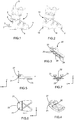
- FIGS 8 to 12 represent an alternative embodiment in which a metal reinforcement is added to the heel piece described above.
- this metal reinforcement is lightweight and small in size, for example in the form of a simple folded sheet of small thickness, is not comparable with the heavy and rigid structure of the Lowtech insert of the state of the art.
- the figure 9 describes more particularly a metal reinforcement 30 according to this embodiment variant.
- This reinforcement is a thin rounded blade, comprising a hook shape 32 at each of its two ends, and comprising an opening 31 at each of its two ends. These openings 31 are intended for positioning at the hollow fastening portions 21 of the heel.
- the rounded surface of the reinforcement has a shape corresponding to the rounded front wall of the heel, so that the reinforcement is positioned on this rounded front wall.
- the manufacturing method of this embodiment variant thus comprises a step of fixing the metal reinforcement 30.
- its two hooks 32 are inserted into slots formed by machining the heel and then the metal reinforcement is fixed by any means, in particular mechanical means such as screwing through at least one opening 31, 34 formed in the metal reinforcement 30.
- the manufacturing method of this embodiment variant comprises a preliminary step of positioning the metal reinforcement 30 in the injection mold before proceeding to the two overinjection stages, finally allowing to imprison the metal reinforcement 30 within the heel.
- the two hooks 32 of the ends of the reinforcement promote its grip in the surinjected plastic material.
- the metal reinforcement 30 is positioned so that the two openings 31 engage the reliefs intended to form the hollow fastening portions 21. This allows the precise positioning without difficulty of the metal reinforcement 30.
- another intermediate opening 34 which also facilitates the maintenance of the metal reinforcement 30 in the manufacturing mold.
- this metal reinforcement improves the rigidity and longevity of the heel, especially at the hollow fixing parts.
- the charged plastic material described above remains necessary and remains used in a zone similar to that described in the previous embodiment.
- the metal reinforcement performs a reinforcing function of the loaded plastic material, in particular at the friction surfaces of the hollow fixing parts.
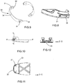
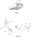
- FIGS. 13 and 14 represent a second embodiment of the heel 20, in which the reinforcement 30 is slightly modified at its two ends, which have openings 33 and no longer hook shapes. These openings 33 have the same function of ensuring the attachment of the reinforcements, either by screwing through these openings, or by the passage of the plastic material loaded through the openings 33 during overinjection, thus forming an anchoring means mechanical reinforcement 30.
- each annular reinforcement 30 is reduced and is in the simple form of two metal rings 35 disposed at the two hollow fastening portions 21 of the heel.
- each annular reinforcement comprises three arms 36 each having an opening 31, to form mechanical anchoring elements. Note, this form rings metal reinforcements allows them rotations when they are positioned in the mold without affecting the final result.
- FIGS 17 to 21 illustrate a rear heel 40 intended to be housed removably in a housing provided at the rear sole of the ski boot.
- This heel is also formed of a combination of a conventional plastic material with a loaded plastic material, manufactured by a double injection.
- the loaded plastic material performs the function of rigid reinforcement of the whole of the heel, and is in particular positioned in rigid areas 42 disposed at the vertical rear wall of the heel and at the level of the sole of the heel.
- Recesses are made in these rear rigid areas to form the elements of cooperation with a rear attachment device of a shoe on a ski touring. This rear heel is thus compliant with the Dynafit® standard.
- metal reinforcements 45 are inserted into these recesses, and fixed by screwing by screws 46. These reinforcements remain optional and alternatively could be removed.
- heelettes and removable relative to the rest of the shoe allows their replacement with other heelettes, either identical, in case of wear, or different, for example for another use of the same shoe. They may advantageously make it possible to form a shoe conforming to the ISO standard for ski touring boots, as previously illustrated.
- the Figures 22 to 25 illustrate for example a heel before practice of descent 50, which allows to form a ski boot format compatible with alpine ski boots as defined by the ISO 5355 standard.
- the front heel 50 is also formed by a double injection of which a plastic material loaded. The latter is at least used to form part of the front surface 54 of the heel which will form the sidewalk of the shoe on which the attachment jaws will engage, as well as to form a friction plate 55 under the lower surface, and more generally for an entire rigid zone 52.
- This heelette also comprises hollow fixing portions 51, compatible with the devices mount ski touring according to the Dynafit® standard, to also use such devices in the descent phase with a ski touring equipped with its traditional front fixing device.
- heelettes separate from the rest of the shoe are fixed to the shoe by any mechanical means, such as screws through through openings 26, 56 formed under the lower surface of the heel.
- the described heelettes use at least one filled plastic material.
- they may be formed integrally of the same charged plastic material in a single injection step.
- they can combine more than two materials.
- the loaded plastic material, and therefore the rigid zone can extend over the entire length of a heel, from its front end to its rear end.
- the invention also relates to a shoe equipped with several sets of removable heelettes of different geometries, but suitable for association with the incomplete sole of the rigid upper of the shoe.
- a ski boot formed by the use of a first set of removable sole can be transformed using a second set of removable sole so as to obtain a sole substantially compatible alternately with a use downhill and climbing, for the practice of ski touring, and / or to form an alpine ski boot.
- these heels will complete the rigid rod to form a shoe compatible with either the ISO standard of alpine skiing, or with the ISO standard of ski touring.
- a result obtained by this technical effect is to allow a compact footwear assembly whose use is provided for a transformation at each change up - down.
Landscapes
- Health & Medical Sciences (AREA)
- General Health & Medical Sciences (AREA)
- Physical Education & Sports Medicine (AREA)
- Footwear And Its Accessory, Manufacturing Method And Apparatuses (AREA)
Claims (14)
- Fersenstück eines Skischuhs, umfassend mindestens einen Zusammenwirkungsbereich, der zum Zusammenwirken mit einem Halteelement einer Vorrichtung zum Befestigen eines Schuhs auf einem Ski geeignet ist, dadurch gekennzeichnet, dass der Zusammenwirkungsbereich einen Bereich (22; 42; 52) aus kurzfaserverstärktem Kunststoff, der durch Einspritzen erhalten ist, aufweist und dass das Fersenstück eines Skischuhs mindestens einen Bereich aus nicht verstärktem Kunststoff aufweist, und dadurch gekennzeichnet, dass:- das Fersenstück eines Skischuhs ein abnehmbares vorderes Fersenstück ist, das zwei hohle Befestigungsteile (21) aufweist, die seitlich in der Nähe des vorderen Endes des Fersenstücks des Skischuhs angeordnet sind, die zum Zusammenwirken mit zwei seitlichen Klemmteilen einer Befestigungsvorrichtung eines Skischuhs auf einem Tourenski geeignet sind, wobei das Fersenstück eines Skischuhs mindestens einen Bereich (22) aus kurzfaserverstärktem Kunststoff an zwei hohlen Befestigungsteilen (21) aufweist, wobei diese Letzteren insbesondere in einem Bereich (22) aus verstärktem Kunststoff erstellt sind, oder- das Fersenstück eines Skischuhs ein abnehmbares hinteres Fersenstück ist, das einen kurzfaserverstärkten Kunststoff aufweist, der mindestens in starren Bereichen (42) angeordnet ist, an der hinteren vertikalen Wand und an der Sohle im hinteren Teil des Fersenstücks eines Schuhs angeordnet sind, und wobei Ausnehmungen in diesen starren Bereichen erstellt sind, um die Elemente zum Zusammenwirken mit einer hinteren Befestigungsvorrichtung eines Schuhs auf einem Tourenski zu bilden.
- Fersenstück eines Skischuhs nach dem vorhergehenden Anspruch, dadurch gekennzeichnet, dass es einen Bereich (22) aus verstärktem Kunststoff aufweist, der sich von einem hohlen Befestigungsteil (21) zum anderen in der Querrichtung des Fersenstücks eines Skischuhs erstreckt und/oder der sich bis zum vorderen Ende des Fersenstücks eines Skischuhs erstreckt.
- Fersenstück eines Skischuhs nach einem der vorhergehenden Ansprüche, dadurch gekennzeichnet, dass es einen starren Bereich aus verstärktem Kunststoff aufweist, der sich über seine ganze Länge erstreckt.
- Fersenstück eines Skischuhs nach einem der vorhergehenden Ansprüche, dadurch gekennzeichnet, dass es eine Metallverstärkung (30; 45) an einem Zusammenwirkungsbereichs, insbesondere von zwei hohlen Befestigungsteilen (21) aufweist.
- Fersenstück eines Skischuhs nach dem vorhergehenden Anspruch, dadurch gekennzeichnet, dass die Metallverstärkung (30) zwei Metallringe (35) aufweist und/oder dass es sich von einem hohlen Befestigungsteil (21) zum anderen kontinuierlich erstreckt, wobei es im Wesentlichen der Stirnfläche des Fersenstücks eines Skischuhs folgt, und/oder dass es die Form eines gebogenen Blechs aufweist.
- Fersenstück eines Skischuhs nach Anspruch 4 oder 5, dadurch gekennzeichnet, dass die Metallverstärkung (30) eine Öffnung (31) an zwei hohlen Befestigungsteilen (21) aufweist.
- Fersenstück eines Skischuhs nach einem der vorhergehenden Ansprüche, dadurch gekennzeichnet, dass der verstärkte Kunststoff eingespritzt ist und Fasern, wie Carbon- oder Glasfasern, aufweist.
- Skischuh, dadurch gekennzeichnet, dass er ein Fersenstück eines Skischuhs nach einem der vorhergehenden Ansprüche aufweist, das mindestens einen Teil seiner Sohle bildet.
- Skischuh nach dem vorhergehenden Anspruch, dadurch gekennzeichnet, dass das Fersenstück des Skischuhs vom Rest des Schuhs getrennt ist und abnehmbar am Rest des Schuhs befestigt ist.
- Skischuh nach dem vorhergehenden Anspruch, dadurch gekennzeichnet, dass das Fersenstück des Skischuhs ein vorderes Fersenstück (20), das zwei hohle Befestigungsteile (21) aufweist, und/oder ein hinteres Fersenstück (40) ist, das mindestens eine Ausnehmung aufweist, die ein Zusammenwirkungselement für das Zusammenwirken mit einem Halteelement einer Befestigungsvorrichtung des Schuhs auf einem Ski bildet.
- Schuhanordnung, umfassend einen steifen Schaft des Typs des Skischuhs, der mit einer unvollständigen Sohle versehen ist, und die mindestens ein Fersenstück eines Skischuhs nach einem der Ansprüche 1 bis 7 aufweist und die dadurch gekennzeichnet ist, dass sie aufweist:- mindestens ein erstes abnehmbares Fersenstück, umfassend eine Stirnfläche (54) und eine Auflageplatte (55), das geeignet ist, die unvollständige Sohle des Schaftes zu vervollständigen, um einen Schuh mit einer Sohle zu bilden, der für das Alpinskifahren geeignet ist,- mindestens ein zweites abnehmbares Fersenstück, das von dem ersten verschieden ist, das geeignet ist, die unvollständige Sohle des Schaftes zu vervollständigen, um einen Schuh zu bilden, der für das Tourenskifahren geeignet ist.
- Verfahren zur Herstellung eines Fersenstück eines Skischuhs nach einem der Ansprüche 1 bis 7, dadurch gekennzeichnet, dass es einen Schritt des Einspritzens eines verstärkten Kunststoffs in ein Formteil aufweist, um mindestens einen Zusammenwirkungsbereich des Fersenstücks des Skischuhs zu bilden, der zum Zusammenwirken mit einem Halteelement einer Vorrichtung zum Befestigen eines Schuhs auf einem Ski geeignet ist, insbesondere ein Formteil, das zwei Reliefs aufweist, die geeignet sind, um zwei hohle Befestigungsteile (21) des Fersenstücks des Skischuhs zu bilden.
- Verfahren zur Herstellung eines Fersenstück eines Skischuhs nach dem vorhergehenden Anspruch, dadurch gekennzeichnet, dass es einen Schritt des Positionierens von mindestens einer Metallverstärkung an zwei Reliefs des Formteils, wie einen Metallring, vor dem Einspritzen des verstärkten Kunststoffs aufweist.
- Verfahren zur Herstellung eines Fersenstück eines Skischuhs nach Anspruch 12 oder 13, dadurch gekennzeichnet, dass es einen weiteren Schritt des Einspritzen eines nicht verstärkten Kunststoffs aufweist.
Priority Applications (1)
| Application Number | Priority Date | Filing Date | Title |
|---|---|---|---|
| EP13425107.3A EP2829188B1 (de) | 2013-07-25 | 2013-07-25 | Skischuh |
Applications Claiming Priority (1)
| Application Number | Priority Date | Filing Date | Title |
|---|---|---|---|
| EP13425107.3A EP2829188B1 (de) | 2013-07-25 | 2013-07-25 | Skischuh |
Publications (2)
| Publication Number | Publication Date |
|---|---|
| EP2829188A1 EP2829188A1 (de) | 2015-01-28 |
| EP2829188B1 true EP2829188B1 (de) | 2018-05-09 |
Family
ID=49226107
Family Applications (1)
| Application Number | Title | Priority Date | Filing Date |
|---|---|---|---|
| EP13425107.3A Active EP2829188B1 (de) | 2013-07-25 | 2013-07-25 | Skischuh |
Country Status (1)
| Country | Link |
|---|---|
| EP (1) | EP2829188B1 (de) |
Cited By (1)
| Publication number | Priority date | Publication date | Assignee | Title |
|---|---|---|---|---|
| US20230069114A1 (en) * | 2021-08-30 | 2023-03-02 | DaleBoot Holdings LLC | Ski boot having cantable sole |
Families Citing this family (1)
| Publication number | Priority date | Publication date | Assignee | Title |
|---|---|---|---|---|
| SI3375312T1 (sl) | 2017-03-17 | 2021-01-29 | Marker Deutschland Gmbh | Otroški smučarski čevelj z izboljšano funkcijo hoje |
Family Cites Families (11)
| Publication number | Priority date | Publication date | Assignee | Title |
|---|---|---|---|---|
| AT381458B (de) | 1985-03-25 | 1986-10-27 | Barthel Fritz | Tourenskibindung |
| FR2766065A1 (fr) * | 1997-07-16 | 1999-01-22 | Salomon Sa | Chaussure bi-matiere pour patinage dit "agressive" et patin la comportant |
| CH695307A5 (fr) * | 2001-09-21 | 2006-03-31 | Lange Int Sa | Chaussure de ski alpin. |
| AT413316B (de) | 2004-01-28 | 2006-02-15 | Barthel Fritz | Lagerplatte und tourenskischuh für ein tourenskibindungssystem |
| DE602004003248T2 (de) * | 2004-09-29 | 2007-05-31 | Lange International S.A. | Sportschuh aus sehr hartem Material |
| ITVE20060010U1 (it) * | 2006-03-03 | 2007-09-04 | Ober Alp Spa | Calzatura perfezionata per sci alpinismo.- |
| ITVE20070024U1 (it) | 2007-07-05 | 2009-01-06 | Ober Alp Spa | Calzatura perfezionata per sci. |
| FR2928523B1 (fr) * | 2008-03-12 | 2015-03-06 | Eurl Gignoux | Chaussure de ski ou de montagne en materiaux composite |
| FR2945185B1 (fr) * | 2009-05-05 | 2011-10-07 | Gignoux Sarl | Dispositif de fixation de ski de randonnee |
| DE202010018184U1 (de) * | 2010-08-18 | 2014-07-23 | Salewa Sport Ag | Kopplungselement für einen Skischuh und Skischuh |
| FR2971675B1 (fr) * | 2011-02-21 | 2014-10-10 | Eurl Gignoux | Coque de chaussure flexible au niveau de l'articulation metatarso-phalangienne |
-
2013
- 2013-07-25 EP EP13425107.3A patent/EP2829188B1/de active Active
Non-Patent Citations (1)
| Title |
|---|
| None * |
Cited By (1)
| Publication number | Priority date | Publication date | Assignee | Title |
|---|---|---|---|---|
| US20230069114A1 (en) * | 2021-08-30 | 2023-03-02 | DaleBoot Holdings LLC | Ski boot having cantable sole |
Also Published As
| Publication number | Publication date |
|---|---|
| EP2829188A1 (de) | 2015-01-28 |
Similar Documents
| Publication | Publication Date | Title |
|---|---|---|
| EP1842442B1 (de) | Sohle von Langlaufskischuhen, die perfektionierte Mittel zur Verankerung eines Verbindungsmittels umfasst, und ein mit einer solchen Sohle ausgestatteter Schuh | |
| CA1136850A (fr) | Procede de fabrication d'une chaussure de sport et chaussure obtenue | |
| EP2762023B1 (de) | Schuhwerk, das ein erstes Schuhelement und ein zweites Schuhelement umfasst | |
| CH688254A5 (fr) | Chaussure de snowboard. | |
| FR3024822A1 (fr) | Chaussure de sport | |
| EP2572599B1 (de) | Schale für Skischuh mit Spoiler | |
| EP1935460B2 (de) | Artikel mit einer Verbindung zur Haltung oder zum Spannen von einem Fuß oder einem Schuh | |
| EP0895727B1 (de) | Sportschuh mit bestimmter Biegsamkeit | |
| EP3195748B1 (de) | Sohle eines langlauf-skischuhs | |
| EP2829188B1 (de) | Skischuh | |
| EP2829187B1 (de) | Skischuh | |
| EP1050325B1 (de) | Rückhaltevorrichtung für einen Snowboardschuh | |
| FR2866791A1 (fr) | Platine de liaison rapide d'une chaussure de cycliste sur une pedale automatique de cycle | |
| FR2958556A1 (fr) | Dispositif d'accueil d'un pied ou d'une chaussure sur un engin de glisse. | |
| EP3673761A1 (de) | Element eines langlauf-skischuhs, das durch koinjektion hergestellt wird | |
| FR2624355A1 (fr) | Piece monobloc destinee a la confection d'une chaussure | |
| EP3123884B1 (de) | Sohle eines gleitsportschuhs | |
| EP3415022B1 (de) | Skischuhelement | |
| EP0785002B1 (de) | Bindungssystem für Schuhe auf Skis | |
| FR2701361A1 (fr) | Dispositif de fermeture à levier-crémaillère pour chaussure de ski. | |
| EP0436444A1 (de) | Skischuh aus Kunststoff | |
| EP2078542B1 (de) | Vorrichtung zur Befestigung eines Schuhs auf einem Schneegleitbrett | |
| FR3136681A1 (fr) | Noyau pour ski et ski incluant un tel noyau | |
| FR3044525A1 (fr) | Languette pour chausson interieur de chaussure de sport | |
| EP1279420A1 (de) | Verfahren zur Herstellung eines Alpinskis sowie derso hergestellte Ski |
Legal Events
| Date | Code | Title | Description |
|---|---|---|---|
| 17P | Request for examination filed |
Effective date: 20130725 |
|
| AK | Designated contracting states |
Kind code of ref document: A1 Designated state(s): AL AT BE BG CH CY CZ DE DK EE ES FI FR GB GR HR HU IE IS IT LI LT LU LV MC MK MT NL NO PL PT RO RS SE SI SK SM TR |
|
| AX | Request for extension of the european patent |
Extension state: BA ME |
|
| PUAI | Public reference made under article 153(3) epc to a published international application that has entered the european phase |
Free format text: ORIGINAL CODE: 0009012 |
|
| R17P | Request for examination filed (corrected) |
Effective date: 20150728 |
|
| RBV | Designated contracting states (corrected) |
Designated state(s): AL AT BE BG CH CY CZ DE DK EE ES FI FR GB GR HR HU IE IS IT LI LT LU LV MC MK MT NL NO PL PT RO RS SE SI SK SM TR |
|
| 17Q | First examination report despatched |
Effective date: 20170317 |
|
| GRAP | Despatch of communication of intention to grant a patent |
Free format text: ORIGINAL CODE: EPIDOSNIGR1 |
|
| INTG | Intention to grant announced |
Effective date: 20171124 |
|
| RIN1 | Information on inventor provided before grant (corrected) |
Inventor name: FREGONI, ANDREA Inventor name: POSATO, TIZIANO Inventor name: PUGET, NICOLAS |
|
| GRAS | Grant fee paid |
Free format text: ORIGINAL CODE: EPIDOSNIGR3 |
|
| GRAA | (expected) grant |
Free format text: ORIGINAL CODE: 0009210 |
|
| AK | Designated contracting states |
Kind code of ref document: B1 Designated state(s): AL AT BE BG CH CY CZ DE DK EE ES FI FR GB GR HR HU IE IS IT LI LT LU LV MC MK MT NL NO PL PT RO RS SE SI SK SM TR |
|
| REG | Reference to a national code |
Ref country code: GB Ref legal event code: FG4D Free format text: NOT ENGLISH |
|
| REG | Reference to a national code |
Ref country code: CH Ref legal event code: EP Ref country code: AT Ref legal event code: REF Ref document number: 996703 Country of ref document: AT Kind code of ref document: T Effective date: 20180515 |
|
| REG | Reference to a national code |
Ref country code: DE Ref legal event code: R096 Ref document number: 602013037170 Country of ref document: DE Ref country code: IE Ref legal event code: FG4D Free format text: LANGUAGE OF EP DOCUMENT: FRENCH |
|
| REG | Reference to a national code |
Ref country code: DE Ref legal event code: R096 Ref document number: 602013037170 Country of ref document: DE |
|
| REG | Reference to a national code |
Ref country code: FR Ref legal event code: PLFP Year of fee payment: 6 |
|
| REG | Reference to a national code |
Ref country code: NL Ref legal event code: MP Effective date: 20180509 |
|
| REG | Reference to a national code |
Ref country code: LT Ref legal event code: MG4D |
|
| PG25 | Lapsed in a contracting state [announced via postgrant information from national office to epo] |
Ref country code: SE Free format text: LAPSE BECAUSE OF FAILURE TO SUBMIT A TRANSLATION OF THE DESCRIPTION OR TO PAY THE FEE WITHIN THE PRESCRIBED TIME-LIMIT Effective date: 20180509 Ref country code: LT Free format text: LAPSE BECAUSE OF FAILURE TO SUBMIT A TRANSLATION OF THE DESCRIPTION OR TO PAY THE FEE WITHIN THE PRESCRIBED TIME-LIMIT Effective date: 20180509 Ref country code: ES Free format text: LAPSE BECAUSE OF FAILURE TO SUBMIT A TRANSLATION OF THE DESCRIPTION OR TO PAY THE FEE WITHIN THE PRESCRIBED TIME-LIMIT Effective date: 20180509 Ref country code: BG Free format text: LAPSE BECAUSE OF FAILURE TO SUBMIT A TRANSLATION OF THE DESCRIPTION OR TO PAY THE FEE WITHIN THE PRESCRIBED TIME-LIMIT Effective date: 20180809 Ref country code: FI Free format text: LAPSE BECAUSE OF FAILURE TO SUBMIT A TRANSLATION OF THE DESCRIPTION OR TO PAY THE FEE WITHIN THE PRESCRIBED TIME-LIMIT Effective date: 20180509 Ref country code: NO Free format text: LAPSE BECAUSE OF FAILURE TO SUBMIT A TRANSLATION OF THE DESCRIPTION OR TO PAY THE FEE WITHIN THE PRESCRIBED TIME-LIMIT Effective date: 20180809 |
|
| PGFP | Annual fee paid to national office [announced via postgrant information from national office to epo] |
Ref country code: DE Payment date: 20180710 Year of fee payment: 6 |
|
| PG25 | Lapsed in a contracting state [announced via postgrant information from national office to epo] |
Ref country code: GR Free format text: LAPSE BECAUSE OF FAILURE TO SUBMIT A TRANSLATION OF THE DESCRIPTION OR TO PAY THE FEE WITHIN THE PRESCRIBED TIME-LIMIT Effective date: 20180810 Ref country code: NL Free format text: LAPSE BECAUSE OF FAILURE TO SUBMIT A TRANSLATION OF THE DESCRIPTION OR TO PAY THE FEE WITHIN THE PRESCRIBED TIME-LIMIT Effective date: 20180509 Ref country code: RS Free format text: LAPSE BECAUSE OF FAILURE TO SUBMIT A TRANSLATION OF THE DESCRIPTION OR TO PAY THE FEE WITHIN THE PRESCRIBED TIME-LIMIT Effective date: 20180509 Ref country code: LV Free format text: LAPSE BECAUSE OF FAILURE TO SUBMIT A TRANSLATION OF THE DESCRIPTION OR TO PAY THE FEE WITHIN THE PRESCRIBED TIME-LIMIT Effective date: 20180509 Ref country code: HR Free format text: LAPSE BECAUSE OF FAILURE TO SUBMIT A TRANSLATION OF THE DESCRIPTION OR TO PAY THE FEE WITHIN THE PRESCRIBED TIME-LIMIT Effective date: 20180509 |
|
| REG | Reference to a national code |
Ref country code: AT Ref legal event code: MK05 Ref document number: 996703 Country of ref document: AT Kind code of ref document: T Effective date: 20180509 |
|
| PG25 | Lapsed in a contracting state [announced via postgrant information from national office to epo] |
Ref country code: CZ Free format text: LAPSE BECAUSE OF FAILURE TO SUBMIT A TRANSLATION OF THE DESCRIPTION OR TO PAY THE FEE WITHIN THE PRESCRIBED TIME-LIMIT Effective date: 20180509 Ref country code: SK Free format text: LAPSE BECAUSE OF FAILURE TO SUBMIT A TRANSLATION OF THE DESCRIPTION OR TO PAY THE FEE WITHIN THE PRESCRIBED TIME-LIMIT Effective date: 20180509 Ref country code: PL Free format text: LAPSE BECAUSE OF FAILURE TO SUBMIT A TRANSLATION OF THE DESCRIPTION OR TO PAY THE FEE WITHIN THE PRESCRIBED TIME-LIMIT Effective date: 20180509 Ref country code: RO Free format text: LAPSE BECAUSE OF FAILURE TO SUBMIT A TRANSLATION OF THE DESCRIPTION OR TO PAY THE FEE WITHIN THE PRESCRIBED TIME-LIMIT Effective date: 20180509 Ref country code: DK Free format text: LAPSE BECAUSE OF FAILURE TO SUBMIT A TRANSLATION OF THE DESCRIPTION OR TO PAY THE FEE WITHIN THE PRESCRIBED TIME-LIMIT Effective date: 20180509 Ref country code: EE Free format text: LAPSE BECAUSE OF FAILURE TO SUBMIT A TRANSLATION OF THE DESCRIPTION OR TO PAY THE FEE WITHIN THE PRESCRIBED TIME-LIMIT Effective date: 20180509 Ref country code: AT Free format text: LAPSE BECAUSE OF FAILURE TO SUBMIT A TRANSLATION OF THE DESCRIPTION OR TO PAY THE FEE WITHIN THE PRESCRIBED TIME-LIMIT Effective date: 20180509 |
|
| REG | Reference to a national code |
Ref country code: DE Ref legal event code: R097 Ref document number: 602013037170 Country of ref document: DE |
|
| PG25 | Lapsed in a contracting state [announced via postgrant information from national office to epo] |
Ref country code: SM Free format text: LAPSE BECAUSE OF FAILURE TO SUBMIT A TRANSLATION OF THE DESCRIPTION OR TO PAY THE FEE WITHIN THE PRESCRIBED TIME-LIMIT Effective date: 20180509 |
|
| REG | Reference to a national code |
Ref country code: CH Ref legal event code: PL |
|
| PLBE | No opposition filed within time limit |
Free format text: ORIGINAL CODE: 0009261 |
|
| STAA | Information on the status of an ep patent application or granted ep patent |
Free format text: STATUS: NO OPPOSITION FILED WITHIN TIME LIMIT |
|
| PG25 | Lapsed in a contracting state [announced via postgrant information from national office to epo] |
Ref country code: LU Free format text: LAPSE BECAUSE OF NON-PAYMENT OF DUE FEES Effective date: 20180725 Ref country code: MC Free format text: LAPSE BECAUSE OF FAILURE TO SUBMIT A TRANSLATION OF THE DESCRIPTION OR TO PAY THE FEE WITHIN THE PRESCRIBED TIME-LIMIT Effective date: 20180509 |
|
| REG | Reference to a national code |
Ref country code: BE Ref legal event code: MM Effective date: 20180731 |
|
| 26N | No opposition filed |
Effective date: 20190212 |
|
| REG | Reference to a national code |
Ref country code: IE Ref legal event code: MM4A |
|
| GBPC | Gb: european patent ceased through non-payment of renewal fee |
Effective date: 20180809 |
|
| PG25 | Lapsed in a contracting state [announced via postgrant information from national office to epo] |
Ref country code: IE Free format text: LAPSE BECAUSE OF NON-PAYMENT OF DUE FEES Effective date: 20180725 Ref country code: LI Free format text: LAPSE BECAUSE OF NON-PAYMENT OF DUE FEES Effective date: 20180731 Ref country code: CH Free format text: LAPSE BECAUSE OF NON-PAYMENT OF DUE FEES Effective date: 20180731 |
|
| PG25 | Lapsed in a contracting state [announced via postgrant information from national office to epo] |
Ref country code: SI Free format text: LAPSE BECAUSE OF FAILURE TO SUBMIT A TRANSLATION OF THE DESCRIPTION OR TO PAY THE FEE WITHIN THE PRESCRIBED TIME-LIMIT Effective date: 20180509 Ref country code: BE Free format text: LAPSE BECAUSE OF NON-PAYMENT OF DUE FEES Effective date: 20180731 |
|
| PG25 | Lapsed in a contracting state [announced via postgrant information from national office to epo] |
Ref country code: GB Free format text: LAPSE BECAUSE OF NON-PAYMENT OF DUE FEES Effective date: 20180809 |
|
| PG25 | Lapsed in a contracting state [announced via postgrant information from national office to epo] |
Ref country code: AL Free format text: LAPSE BECAUSE OF FAILURE TO SUBMIT A TRANSLATION OF THE DESCRIPTION OR TO PAY THE FEE WITHIN THE PRESCRIBED TIME-LIMIT Effective date: 20180509 |
|
| PG25 | Lapsed in a contracting state [announced via postgrant information from national office to epo] |
Ref country code: MT Free format text: LAPSE BECAUSE OF FAILURE TO SUBMIT A TRANSLATION OF THE DESCRIPTION OR TO PAY THE FEE WITHIN THE PRESCRIBED TIME-LIMIT Effective date: 20180509 |
|
| REG | Reference to a national code |
Ref country code: DE Ref legal event code: R119 Ref document number: 602013037170 Country of ref document: DE |
|
| PG25 | Lapsed in a contracting state [announced via postgrant information from national office to epo] |
Ref country code: TR Free format text: LAPSE BECAUSE OF FAILURE TO SUBMIT A TRANSLATION OF THE DESCRIPTION OR TO PAY THE FEE WITHIN THE PRESCRIBED TIME-LIMIT Effective date: 20180509 |
|
| PG25 | Lapsed in a contracting state [announced via postgrant information from national office to epo] |
Ref country code: DE Free format text: LAPSE BECAUSE OF NON-PAYMENT OF DUE FEES Effective date: 20200201 |
|
| PG25 | Lapsed in a contracting state [announced via postgrant information from national office to epo] |
Ref country code: PT Free format text: LAPSE BECAUSE OF FAILURE TO SUBMIT A TRANSLATION OF THE DESCRIPTION OR TO PAY THE FEE WITHIN THE PRESCRIBED TIME-LIMIT Effective date: 20180509 Ref country code: HU Free format text: LAPSE BECAUSE OF FAILURE TO SUBMIT A TRANSLATION OF THE DESCRIPTION OR TO PAY THE FEE WITHIN THE PRESCRIBED TIME-LIMIT; INVALID AB INITIO Effective date: 20130725 |
|
| PG25 | Lapsed in a contracting state [announced via postgrant information from national office to epo] |
Ref country code: CY Free format text: LAPSE BECAUSE OF FAILURE TO SUBMIT A TRANSLATION OF THE DESCRIPTION OR TO PAY THE FEE WITHIN THE PRESCRIBED TIME-LIMIT Effective date: 20180509 Ref country code: MK Free format text: LAPSE BECAUSE OF NON-PAYMENT OF DUE FEES Effective date: 20180509 |
|
| PG25 | Lapsed in a contracting state [announced via postgrant information from national office to epo] |
Ref country code: IS Free format text: LAPSE BECAUSE OF FAILURE TO SUBMIT A TRANSLATION OF THE DESCRIPTION OR TO PAY THE FEE WITHIN THE PRESCRIBED TIME-LIMIT Effective date: 20180909 |
|
| PGFP | Annual fee paid to national office [announced via postgrant information from national office to epo] |
Ref country code: IT Payment date: 20210713 Year of fee payment: 9 |
|
| P01 | Opt-out of the competence of the unified patent court (upc) registered |
Effective date: 20230530 |
|
| PG25 | Lapsed in a contracting state [announced via postgrant information from national office to epo] |
Ref country code: IT Free format text: LAPSE BECAUSE OF NON-PAYMENT OF DUE FEES Effective date: 20220725 |
|
| PGFP | Annual fee paid to national office [announced via postgrant information from national office to epo] |
Ref country code: FR Payment date: 20250730 Year of fee payment: 13 |