EP3702005A1 - Heelholder - Google Patents
Heelholder Download PDFInfo
- Publication number
- EP3702005A1 EP3702005A1 EP20156651.0A EP20156651A EP3702005A1 EP 3702005 A1 EP3702005 A1 EP 3702005A1 EP 20156651 A EP20156651 A EP 20156651A EP 3702005 A1 EP3702005 A1 EP 3702005A1
- Authority
- EP
- European Patent Office
- Prior art keywords
- holding
- heel
- ski
- unit
- automatic
- Prior art date
- Legal status (The legal status is an assumption and is not a legal conclusion. Google has not performed a legal analysis and makes no representation as to the accuracy of the status listed.)
- Pending
Links
- 230000027455 binding Effects 0.000 claims abstract description 76
- 238000009739 binding Methods 0.000 claims abstract description 76
- 230000005540 biological transmission Effects 0.000 claims abstract description 26
- 230000008901 benefit Effects 0.000 description 37
- 230000007246 mechanism Effects 0.000 description 27
- 230000009194 climbing Effects 0.000 description 8
- 230000036316 preload Effects 0.000 description 6
- 230000009467 reduction Effects 0.000 description 6
- 230000001419 dependent effect Effects 0.000 description 4
- 238000010276 construction Methods 0.000 description 3
- 230000003993 interaction Effects 0.000 description 3
- 230000000694 effects Effects 0.000 description 2
- 238000009472 formulation Methods 0.000 description 2
- 239000000203 mixture Substances 0.000 description 2
- 230000008859 change Effects 0.000 description 1
- 239000007788 liquid Substances 0.000 description 1
- 238000000034 method Methods 0.000 description 1
- 230000035939 shock Effects 0.000 description 1
- 230000009466 transformation Effects 0.000 description 1
- XLYOFNOQVPJJNP-UHFFFAOYSA-N water Substances O XLYOFNOQVPJJNP-UHFFFAOYSA-N 0.000 description 1
Images


Classifications
-
- A—HUMAN NECESSITIES
- A63—SPORTS; GAMES; AMUSEMENTS
- A63C—SKATES; SKIS; ROLLER SKATES; DESIGN OR LAYOUT OF COURTS, RINKS OR THE LIKE
- A63C9/00—Ski bindings
- A63C9/006—Ski bindings with a climbing wedge
-
- A—HUMAN NECESSITIES
- A63—SPORTS; GAMES; AMUSEMENTS
- A63C—SKATES; SKIS; ROLLER SKATES; DESIGN OR LAYOUT OF COURTS, RINKS OR THE LIKE
- A63C9/00—Ski bindings
- A63C9/08—Ski bindings yieldable or self-releasing in the event of an accident, i.e. safety bindings
- A63C9/0807—Ski bindings yieldable or self-releasing in the event of an accident, i.e. safety bindings for both towing and downhill skiing
-
- A—HUMAN NECESSITIES
- A63—SPORTS; GAMES; AMUSEMENTS
- A63C—SKATES; SKIS; ROLLER SKATES; DESIGN OR LAYOUT OF COURTS, RINKS OR THE LIKE
- A63C9/00—Ski bindings
- A63C9/08—Ski bindings yieldable or self-releasing in the event of an accident, i.e. safety bindings
- A63C9/084—Ski bindings yieldable or self-releasing in the event of an accident, i.e. safety bindings with heel hold-downs, e.g. swingable
- A63C9/0843—Ski bindings yieldable or self-releasing in the event of an accident, i.e. safety bindings with heel hold-downs, e.g. swingable with a plurality of mobile jaws
-
- A—HUMAN NECESSITIES
- A63—SPORTS; GAMES; AMUSEMENTS
- A63C—SKATES; SKIS; ROLLER SKATES; DESIGN OR LAYOUT OF COURTS, RINKS OR THE LIKE
- A63C9/00—Ski bindings
- A63C9/08—Ski bindings yieldable or self-releasing in the event of an accident, i.e. safety bindings
- A63C9/084—Ski bindings yieldable or self-releasing in the event of an accident, i.e. safety bindings with heel hold-downs, e.g. swingable
- A63C9/0845—Ski bindings yieldable or self-releasing in the event of an accident, i.e. safety bindings with heel hold-downs, e.g. swingable the body or base or a jaw pivoting about a vertical axis, i.e. side release
-
- A—HUMAN NECESSITIES
- A63—SPORTS; GAMES; AMUSEMENTS
- A63C—SKATES; SKIS; ROLLER SKATES; DESIGN OR LAYOUT OF COURTS, RINKS OR THE LIKE
- A63C9/00—Ski bindings
- A63C9/08—Ski bindings yieldable or self-releasing in the event of an accident, i.e. safety bindings
- A63C9/084—Ski bindings yieldable or self-releasing in the event of an accident, i.e. safety bindings with heel hold-downs, e.g. swingable
- A63C9/0846—Details of the release or step-in mechanism
-
- A—HUMAN NECESSITIES
- A63—SPORTS; GAMES; AMUSEMENTS
- A63C—SKATES; SKIS; ROLLER SKATES; DESIGN OR LAYOUT OF COURTS, RINKS OR THE LIKE
- A63C9/00—Ski bindings
- A63C9/08—Ski bindings yieldable or self-releasing in the event of an accident, i.e. safety bindings
- A63C9/086—Ski bindings yieldable or self-releasing in the event of an accident, i.e. safety bindings using parts which are fixed on the shoe of the user and are releasable from the ski binding
-
- A—HUMAN NECESSITIES
- A63—SPORTS; GAMES; AMUSEMENTS
- A63C—SKATES; SKIS; ROLLER SKATES; DESIGN OR LAYOUT OF COURTS, RINKS OR THE LIKE
- A63C9/00—Ski bindings
- A63C2009/008—Ski bindings with a binding element sliding along a rail during use or setting
Definitions
- the invention relates to an automatic heel unit for a ski binding, in particular a touring ski binding.
- This automatic heel unit comprises a base unit for fastening on the surface of a ski and a heel holder with at least one holding means for holding a ski boot in a heel area of the ski boot, the automatic heel unit having a descent configuration in which the heel holder is in a holding position and the at least one holding means can interact with the heel area of the ski boot held in the ski binding in such a way that the heel area of the ski boot is held down in a lowered position.
- the automatic heel unit comprises a radial bearing, by means of which the heel holder is mounted on the base unit so as to be pivotable about a substantially vertically aligned, geometric pivot axis relative to the base unit and can thus be pivoted away from its holding position starting from its holding position along an adjustment path around the pivot axis
- Radial bearing has a pin which is formed on a first of the two units of base unit and heel holder, and the radial bearing has a receptacle which is formed on a second of the two units of base unit and heel holder, wherein the pin is rotatably inserted into the receptacle, whereby the heel holder is pivotably mounted on the base unit about the pivot axis relative to the base unit.
- the automatic heel unit comprises a pretensioning device, by means of which the heel holder can be pretensioned towards its holding position in a first area of the adjustment path, the pretensioning device comprising a first pushing element with a first positioning structure and an elastic element, the first pushing element being generated by the elastic element and along an alignment axis of the elastic element in a first direction aligned first force with the first positioning structure can be pressed against a first counter structure when the heel holder is located in the first region of the adjustment path to preload the heel holder in the first region of the adjustment path towards its holding position.
- the pretensioning device comprising a first pushing element with a first positioning structure and an elastic element, the first pushing element being generated by the elastic element and along an alignment axis of the elastic element in a first direction aligned first force with the first positioning structure can be pressed against a first counter structure when the heel holder is located in the first region of the adjustment path to preload the heel holder in the first region of the adjustment path towards its holding position.
- Automatic heel units in the technical field mentioned above are known. Their task is to ensure that the heel area of the ski boot is reliably fixed on the ski in a downhill configuration.
- some such automatic heel machines also enable a safety release based on the descent configuration, in which the heel area of the ski boot is released. This can be, for example, a safety release in the forward direction or a lateral safety release.
- the term “safety release” means that the automatic heel unit releases the heel area of the ski boot if the energy of an impact on the ski boot, ski binding or ski exceeds a predetermined value. It is irrelevant whether the automatic heel is in the downhill configuration or in another configuration after the ski boot has been released. In the event of impacts whose energy does not exceed this value, the automatic heel unit remains in the downhill configuration and keeps the heel area of the ski boot locked in a position lowered towards the ski.
- an automatic heel device generally depends on which function the ski binding to which the automatic heel device belongs is to fulfill.
- Downhill ski bindings for example, are only used for downhill skiing and skiing on ski lifts.
- touring ski bindings are also used for walking on skis, in particular for climbing with the help of climbing skins attached to the skis.
- Cross-country bindings on the other hand, are used for cross-country skiing and telemark bindings for skiing with the telemark technique.
- downhill ski bindings only have to ensure a reliable fixation of the ski boot on the ski in a so-called holding position.
- Some automatic heel machines also have a so-called entry configuration or release configuration, in which they enable entry into the ski binding.
- touring ski bindings have a walking position in which the ski boot, like cross-country and telemark bindings, can be pivoted about an axis oriented horizontally in the transverse direction of the ski and can be lifted off the ski in the heel area, which enables a joint movement between the ski boot and the ski for walking.
- the automatic heel can be in the walking position of a touring ski binding in different configurations depending on the construction and type of touring ski binding. For example, he can be in his departure configuration, in an entry configuration, in a release configuration or in a walking configuration.
- a heel machine is also required for such a cross-country or telemark binding, by means of which the ski boot can be locked in its heel area towards the ski, and which the heel area of the ski boot can be used for walking in the walking position of the cross-country or telemark binding.
- Touring ski bindings can basically be divided into two types.
- One type comprises a ski boot carrier which can be pivoted relative to the ski and on which the ski boot is held by binding jaws.
- a representative member of this type of touring ski bindings is in the EP 0 754 079 B1 (Fritschi AG).
- the second type relies on ski boots with stiff soles.
- the ski boot is pivotably mounted in its toe area in a ski-mounted front machine.
- the automatic heel unit is also firmly attached to the ski at a distance from the automatic front unit adapted to the length of the ski boot sole and holds the ski boot down in the heel area in the downhill position of the binding.
- ski boots suitable for this type of binding typically have two lateral recesses in the toe area for the pivotable mounting in the front automat. Furthermore, in the heel area they have recesses which are open to the rear and into which the holding means of the automatic heel unit can engage.
- a (fictitious) ski is often used as a reference system to describe such binding systems, it being assumed that the binding is mounted on this ski. This habit is taken over in the present text.
- the term "longitudinal direction of the ski” means along the alignment of the longitudinal axis of the ski.
- "parallel to the ski” means oriented along the longitudinal axis of the ski for an elongate object. For a flat object, however, the term “parallel to the ski” means aligned parallel to the sliding surface of the ski.
- transverse direction of the ski means a direction transverse to the longitudinal direction of the ski, which, however, does not have to be oriented precisely at right angles to the longitudinal axis of the ski.
- ski center in turn means a center of the ski, seen in the transverse direction of the ski, while the term “ski fixed” means not movable with respect to the ski. It should also be noted that terms that do not contain the word “ski” also refer to the reference system of the (fictitious) ski.
- front”, “rear”, “top”, “bottom” and “side” refer to “front”, “back”, “top”, “bottom” and “side” of the ski.
- terms such as “horizontal” and “vertical” also relate to the ski, where “horizontal” means lying in a plane parallel to the ski and “vertical” means oriented perpendicular to this plane.
- a touring ski binding of the second type introduced above is in the EP 0 199 098 A2 (Barthel) and is sold under the name Dynafit.
- a front machine of this system has two clamping parts, each with a pin aligned in the transverse direction of the ski, which engage in recesses in the toe area of the ski boot from the sides when entering the touring ski binding.
- the pins form a pivot bearing of the ski boot, on which the ski boot can be pivoted relative to the ski about an axis oriented horizontally in the transverse direction of the ski.
- a heel machine of this system which is separate from the front machine, has a base element for attachment to a ski and a heel holder for holding the ski boot in the heel area of the ski boot.
- the heel holder is mounted on a vertically oriented pin arranged on the base element and is thereby mounted on the base element so as to be pivotable about a vertically oriented, geometric pivot axis relative to the base element.
- the heel holder In the downhill configuration of the automatic heel unit, the heel holder is in a holding position. In this holding position, two pins arranged on the heel holder are oriented towards the front automaton, whereby they can engage in recesses in the heel of the ski boot and thereby lock the ski boot in a position lowered towards the ski.
- the ski boot When getting into touring ski bindings, the ski boot is first stored in the front machine. Then the heel of the ski boot is lowered onto the pins of the heel holder from above. Since the recesses in the heel of the ski boot are largely open at the bottom, the recesses are thereby guided over the pins, whereupon the pins snap into locking recesses in the recesses.
- both pins can be pressed apart against a spring force, whereby they slide out of the locking depressions and the recesses and can release the heel of the ski boot upwards.
- both pins are each arranged on a lever, the levers each being mounted on the heel holder so that they can pivot in a horizontal plane. Both levers are preloaded with a spring force, so that the two pins are pressed towards each other. By adjusting the spring force, the force can be specified which is required to enable forward tripping. This enables a safety release in the forward direction.
- the automatic heel unit also enables a lateral safety release.
- the heel holder can be pivoted around a vertically aligned, geometric pivot axis against a spring force on both sides until the two pins are pivoted to the side and the heel area of the ski boot is released on the corresponding side.
- the pin of the base element has a flat surface on its rear side, which is aligned horizontally to the rear with its normal vector. A piston mounted in the heel holder and pretensioned forwards by a spring is pressed against this surface of the pin in the holding position.
- the piston When the heel holder is pivoted away from its holding position about the pivot axis on one of the two sides, the piston is pivoted with it and tilted relative to the surface of the pin. This moves the piston backwards against the spring force. The heel holder is thus biased towards its holding position due to the spring force.
- the preload of the spring By setting the preload of the spring, the value can be specified which must be exceeded by the energy of an impact on the ski, ski binding or ski so that a lateral safety release occurs.
- a heel machine according to EP 0 199 098 A2 can also be brought into an ascent position by turning the heel holder around the pivot axis by the skier, as with a lateral safety release, until the two pins have pivoted to the side out of the path of the heel of the ski boot.
- the heel holder has several rotational positions in which the pins are pivoted out of the movement path of the heel. These individual rotational positions are each predetermined by a spring catch for locking the heel holder. When the heel holder is in one of these rotational positions, the movement path of the heel of the ski boot is free and the ski boot can be lowered down to the ski.
- a support arranged on the heel holder is in each case pivoted a certain distance from the ski in the path of movement of the heel of the ski boot.
- Each such support prevents the ski boot from lowering towards the ski at a different distance from the ski.
- different climbing aids can be set by positioning the heel holder in the various rotational positions.
- the automatic heel unit according to EP 0 199 098 A2 (Barthel) is constructed very compactly. However, it has the disadvantage that the mounting of the heel holder on the base element is not particularly stable.
- the object of the invention is to create an automatic heel unit belonging to the technical field mentioned at the beginning, which is of compact construction and at the same time enables the heel holder to be stably supported on the base element.
- the elastic element is arranged in the pin, the orientation axis of the elastic element being oriented perpendicular to the pivot axis, and the first counter-structure being assigned to the second of the two units comprising the base unit and heel holder.
- the base unit can thus be designed in one piece or in several pieces.
- the base unit can EP 0 199 098 A2 (Barthel) be designed in one piece as a base element. If the base unit is constructed in several pieces, it can, for example, as in the case of WO 2012/024809 A1 (Fritschi AG - Swiss Bindings) described automatic heel a base plate for attachment to the surface of a ski and a slide which is mounted on the base plate in the longitudinal direction of the ski and on which the heel holder is mounted pivotably about the pivot axis.
- the position of the slide in the longitudinal direction of the ski relative to the base plate can be adjusted by means of a screw in order to be able to adjust the position of the heel holder in the longitudinal direction of the ski relative to the front automatic device of the ski binding, so that the ski binding is adapted to different sized ski boots can be.
- the slide can be pretensioned with a spring to a front position relative to the base plate, the heel holder together with the slide can be pushed backwards against the pretension of the spring in order to avoid changes in distance between the automatic front end and the heel holder, which occur when the ski is bent can compensate.
- the heel holder forms a unit and can be designed in one piece or in several pieces.
- the heel holder can also, for example, as in the EP 3 167 943 A1 (Fritschi AG) described by a heel hold-down device as well as a forwardly protruding heel support structure with two forwardly protruding, elongated projections seen in the vertical direction.
- the heel holder can also be used, for example, as in the EP 0 199 098 A2 (Barthel) described to be designed as a unit with two forward pointing pins.
- the heel holder can also be designed differently.
- the pin is formed on a first of the two units comprising the base unit and heel holder, while the receptacle is formed on a second of the two units comprising the base unit and heel holder.
- the pin can be formed on the base unit, while the receptacle is formed on the heel holder.
- the pin can also be formed on the heel holder, while the receptacle can be formed on the base unit.
- the radial bearing is designed, as long as the radial bearing has a pin and a receptacle, the pin being inserted rotatably into the receptacle, whereby the heel holder can pivot about a substantially vertically oriented, geometric pivot axis relative to the base unit the base unit is stored.
- the radial bearing preferably prevents a translational movement of the heel holder relative to the base unit in a direction perpendicular to the pivot axis.
- the base unit can also have two elements have which are movable relative to one another perpendicular to the pivot axis, wherein the radial bearing is arranged on one of these two elements.
- the other of the two elements of the base unit can perform a translational movement relative to the heel holder perpendicular to the pivot axis.
- a movement of the element of the base unit on which the radial bearing is arranged relative to the heel holder perpendicular to the pivot axis of the radial bearing is still prevented.
- the formulation continues to apply that the radial bearing prevents a translational movement of the heel holder relative to the base unit perpendicular to the pivot axis.
- the base unit has two elements which can be moved relative to one another perpendicular to the pivot axis, the radial bearing being arranged on one of these two elements, there is the possibility that the pivot axis is displaced relative to the base unit when the heel holder moves along the adjustment path or that the pivot axis remains in an unchanged position relative to the base unit or relative to the element of the base unit on which the radial bearing is arranged.
- the elastic element of the prestressing device can thus be designed in one piece or in several pieces.
- the elastic element can be a spring, in particular a spiral spring.
- the elastic element can also comprise, for example, two or more spiral springs arranged one inside the other.
- the elastic element is arranged in the pin.
- This preferably means that preferably 70% or more of a volume of the elastic element, particularly preferably 90% or more of the volume of the elastic element, very particularly preferably the entire volume of the elastic element is located within an inner volume of the pin.
- the inner volume of the pin is preferably limited in the radial direction by a jacket surface of the pin and in the axial direction by a distal end of the pin and a proximal end of the pin. It is irrelevant whether the pin has a continuous circumferential surface has or whether there are gaps in the lateral surface of the pin. If there are one or more gaps in the lateral surface of the pin, the internal volume of the pin in the area of the respective gap is preferably limited by a (fictitious) continuously differentiable continuation of the lateral surface adjoining the gap.
- the pivot axis about which the heel holder is pivotably mounted on the base unit by the radial bearing relative to the base unit is oriented essentially vertically. This preferably means that an angle between an exactly vertical line and the pivot axis is less than 45 degrees.
- the pivot axis about which the heel holder is pivotably mounted on the base unit relative to the base unit by the radial bearing is particularly preferably oriented vertically.
- the alignment axis of the elastic element is aligned perpendicular to the pivot axis.
- the alignment axis of the elastic element is preferably aligned essentially horizontally, particularly preferably horizontally.
- the alignment axis of the elastic element is preferably determined by the first force aligned in the first direction or by the first direction.
- the alignment axis of the elastic element can also coincide with a longitudinal axis of the elastic element. This is the case, for example, with a spiral spring as an elastic element, which is compressed or pulled apart along its longitudinal axis and is thus pretensioned in order to generate the first force along its longitudinal axis.
- the first counter structure is assigned to the second of the two units comprising the base unit and heel holder.
- the first counter-structure is preferably held in a rotationally fixed manner on the second of the two units comprising the base unit and heel holder, particularly preferably in a rotationally fixed manner on the receptacle.
- the first counter-structure rotates together with the second of the two units comprising the base unit and heel holder relative to the pin when the heel holder is rotated about the pivot axis relative to the base unit.
- the first counter-structure is in the axial direction relative to the second of the two Units made up of the base unit and heel holder are movably mounted on the second of the two units made up of the base unit and heel holder or in the axial direction relative to the second of the two units made up of the base unit and heel holder on the receptacle.
- This has the advantage that the heel holder can be pretensioned very well towards its holding position in the first area of the adjustment path, but the first counter-structure can also be moved along the pivot axis.
- a further functionality of the automatic heel unit such as, for example, a safety release in the forward direction can also be enabled or even controlled by the first counter structure.
- the first counter-structure is fixedly arranged on the second of the two units comprising the base unit and heel holder, particularly preferably fixedly on the receptacle. This has the advantage that the heel holder can be optimally pretensioned towards its holding position in the first area of the adjustment path.
- the solution according to the invention has the advantage that, in an automatic heel unit with a predetermined size, the pin can be designed with a comparatively large diameter, since the elastic element is arranged in the pin and not outside the pin. As a result, the pin has a comparatively great stability, so that the heel holder can be mounted comparatively stable on the base element.
- the solution according to the invention enables a compactly constructed automatic heel unit, which at the same time enables the heel holder to be stably supported on the base element.
- the first impact element can be pressed with the first positioning structure against a first counter-structure due to a first force generated by the elastic element and oriented along an alignment axis of the elastic element in a first direction.
- the first impact element with the first positioning structure can be pressed against the first counter structure with a first impact element force due to the first force.
- the first impact element force with which the first impact element with the first positioning structure can be pressed against the first counter-structure is the same as the first force which is generated by the elastic element and along the Alignment axis of the elastic element is aligned in the first direction.
- the elastic element preferably acts directly with the first force on the first impact element in order to press the first impact element with the first positioning structure against the first counter-structure.
- the first impact element force differs from the first force.
- the reason for this can be, for example, a deflection mechanism or a lever mechanism of the automatic heel which causes a deflection and / or an increase or reduction of the first force into the first impact element force. Therefore, in this second preferred variant, an absolute amount of the first impact element force differs from an absolute amount of the first force and / or an alignment of the first impact element force differs from an alignment of the first force.
- the automatic heel unit preferably comprises a deflection mechanism or a lever mechanism which causes a deflection and / or an increase or reduction of the first force into the first impact element force.
- the first pusher element is advantageously mounted in the pin so as to be movable radially to the pivot axis, particularly preferably mounted in the pin such that it can be moved radially to the pivot axis.
- This has the advantage that the automatic heel unit can be constructed compactly.
- the first pusher element is particularly preferably movably or displaceably mounted directly on the pin.
- the automatic heel unit can be constructed in a particularly simple manner, since no additional elements are required for mounting the first pushing element in the pin.
- the first pusher element can be moved or displaced radially to the pivot axis on an element other than the pin in the pin.
- the first pusher element is not mounted so as to be radially movable in the pin.
- the pretensioning device comprises a second pushing element with a second positioning structure, the second pushing element with the second positioning structure against one of the second due to a second force generated by the elastic element and aligned along the orientation axis of the elastic element in a second direction opposite to the first direction the two units of the base unit and heel holder associated second counter structure can be pressed when the heel holder is in the first area of the adjustment path in order to bias the heel holder in the first area of the adjustment path towards its holding position.
- This has the advantage that a better power transmission to the second of the two units comprising the base unit and heel holder can be achieved due to the first push element and the second push element in order to preload the heel holder in the first area of the adjustment path towards its holding position.
- the second counter-structure is preferably held in a rotationally fixed manner on the second of the two units comprising the base unit and heel holder, particularly preferably in a rotationally fixed manner on the receptacle.
- the second counter structure rotates together with the second of the two units made up of the base unit and heel holder relative to the pin when the heel holder is rotated about the pivot axis relative to the base unit.
- the second counter-structure is movable in the axial direction relative to the second of the two units comprising the base unit and heel holder on the second of the two units comprising the base unit and heel holder or in the axial direction relative to the second of the two units comprising the base unit and heel holder stored at the intake.
- the heel holder can be pretensioned very well towards its holding position in the first area of the adjustment path, but the second counter-structure can also be moved along the pivot axis.
- a further functionality of the automatic heel unit such as a safety release in the forward direction, can also be enabled or even controlled by the second counter structure.
- the second counter-structure is fixedly arranged on the second of the two units comprising the base unit and heel holder, particularly preferably fixedly on the receptacle. This has the advantage that the heel holder can be optimally pretensioned towards its holding position in the first area of the adjustment path.
- the second push element is preferably with the second positioning structure with a second push element force due to the second force against the second Pressable counter structure.
- the second impact element force with which the second impact element with the second positioning structure can be pressed against the second counter structure is the same as the second force generated by the elastic element and along the alignment axis of the elastic element in the first direction opposite, second direction is aligned.
- the elastic element preferably acts directly with the second force on the second impact element in order to press the second impact element with the second positioning structure against the second counter-structure.
- the second impact element force differs from the second force.
- the reason for this can be, for example, a deflection mechanism or a lever mechanism of the automatic heel which causes a deflection and / or an increase or reduction of the second force into the second impact element force. Therefore, in this second preferred variant, an absolute amount of the second impact element force differs from an absolute amount of the second force and / or an alignment of the first impact element force differs from an alignment of the second force.
- the automatic heel unit preferably comprises a deflection mechanism or a lever mechanism which causes a deflection and / or an increase or reduction of the second force into the second impact element force.
- the pretensioning device does not include such a second push element.
- the pretensioning device comprises a second pushing element with a second positioning structure, the second pushing element having the second positioning structure against one of the second, due to a second force generated by the elastic element and aligned along the orientation axis of the elastic element in a second direction opposite to the first direction
- the second counter-structure assigned to both units comprising the base unit and heel holder can be pressed when the heel holder is in the first area of the adjustment path in order to preload the heel holder in the first area of the adjustment path towards its holding position, an absolute amount of the first force is preferably the same as a Absolute amount of the second force.
- the second pusher element is preferably mounted in the pin so as to be movable radially to the pivot axis, particularly preferably mounted in the pin so as to be movable radially to the pivot axis.
- This has the advantage that the automatic heel unit can be constructed compactly.
- the second pusher element is particularly preferably movably or displaceably mounted directly on the pin.
- This has the advantage that the automatic heel unit can be constructed in a particularly simple manner, since no additional elements are required for mounting the second pusher element in the pin.
- the second pusher element is mounted on an element other than the pin in the pin so that it can be moved or displaced radially to the pivot axis.
- the second pusher element is not mounted so that it can move radially in the pin.
- both the first pusher element and the second pusher element are mounted in the pin so as to be movable radially to the pivot axis, very particularly preferably mounted so as to be displaceable, the first pusher element and the second pusher element preferably being mounted movably or displaceably directly on the pin.
- the first pushing element is preferably mounted movably or displaceably along a straight line
- the second pushing element preferably being mounted movably or displaceably along a straight continuation of the straight line.
- first pusher element or only the second pusher element is mounted in the pin so as to be movable or displaceable radially to the pivot axis, or that neither the first pusher element nor the second pusher element is mounted to move radially to the pivot axis in the pin.
- the pretensioning device comprises a second pushing element with a second positioning structure, the second pushing element having the second positioning structure against one of the second, due to a second force generated by the elastic element and aligned along the orientation axis of the elastic element in a second direction opposite to the first direction
- the second counter-structure assigned to both units comprising the base unit and heel holder can be pressed when the heel holder is in the first area of the adjustment path in order to pretension the heel holder in the first area of the adjustment path towards its holding position
- the first pushing element is preferably on a first side of the elastic element arranged and the second impact element is arranged on a second side of the elastic element opposite the first side of the elastic element.
- the elastic element is preferably clamped between the first pushing element and the second pushing element.
- the first pusher element and the second pusher element are each movably or slidably mounted in the pin radially to the pivot axis, the elastic element being clamped between the first pusher element and the second pusher element and only via the first pusher element and the second pusher element is held in the pin.
- first pusher element and the second pusher element are each movably or slidably mounted in the pin radially to the pivot axis, the elastic element being fastened to the pin in its central area and clamped between the first pusher element and the second pusher element.
- both the first pusher element and the second pusher element are particularly preferably mounted so that they can be moved or displaced directly on the pin.
- other arrangements are also possible in which the elastic element is clamped between the first pushing element and the second pushing element.
- the first striker force and the second striker force are opposite, i.e. aligned in opposite directions, an absolute amount of the first impact element force preferably being essentially the same, particularly preferably the same as an absolute amount of the second impact element force.
- This has the advantage that the two pushing elements are pressed symmetrically away from the pivot axis or symmetrically towards the pivot axis against the respective counter structure, whereby a force acting in the radial direction on the radial bearing is minimized due to the pretension of the elastic element.
- the load on the radial bearing can accordingly be reduced and the service life of the automatic heel can be increased.
- first impact element force is preferably the same as the first force and the second impact element force is the same as the second force.
- first impact element force and the second impact element force are the same, i.e. are aligned in the same direction, or that the first impact element force and the second impact element force are aligned at an angle between 0 ° and 180 °, particularly preferably at an angle between 10 ° and 170 ° to one another.
- the pretensioning device comprises a second pushing element with a second positioning structure, the second pushing element having the second positioning structure against one of the second, due to a second force generated by the elastic element and aligned along the orientation axis of the elastic element in a second direction opposite to the first direction
- the second counter-structure associated with both units comprising the base unit and heel holder can be pressed when the heel holder is in the first area of the adjustment path, in order to bias the heel holder in the first area of the adjustment path towards its holding position, and if the first push element is arranged on a first side of the elastic element and the second impact element is arranged on a second side of the elastic element opposite the first side of the elastic element, the first counter-structure is preferably oriented from the pivot axis viewed in a first radial direction, and the second counter structure, viewed from the pivot axis, is arranged in a second radial direction opposite to the first radial direction.
- first counter-structure is arranged in a first radial direction, seen from the pivot axis, while the second counter-structure is not arranged in a second radial direction, seen from the pivot axis, which is opposite to the first radial direction.
- a pretensioning of the elastic element is preferably adjustable in order to adjust the first force generated by the elastic element and, if necessary, the second force generated by the elastic element. This has the advantage that the pretension with which the heel holder is pretensioned towards its holding position in the first area of the adjustment path can be adjusted.
- the pretension of the elastic element cannot be adjusted.
- Such an alternative has the advantage that the automatic heel unit can be constructed more simply.
- the automatic heel can be constructed in such a way that it has less weight.
- the first of the two units composed of the base unit and heel holder is the base unit and the second of the two units composed of the base unit and Heel holder the heel holder.
- This has the advantage that the pin is arranged on the base unit and that the receptacle is arranged on the heel holder.
- the heel holder with the receptacle is slipped over the pin from above.
- any liquid that has accumulated between the pin and radial bearing, such as water can flow out of the receptacle. Accordingly, icing up of the automatic heel is prevented in a simple manner.
- the first of the two units comprising the base unit and heel holder is the heel holder and the second of the two units comprising the base unit and heel holder is the base unit.
- This has the advantage that the pin is arranged on the heel holder and that the elastic element and the pushing element are thus pivoted with the heel holder relative to the base unit when the heel holder is pivoted about the pivot axis relative to the base unit. Since the elastic element can thus be kept in the same position relative to the heel holder, apart from a change in the pretensioning of the elastic element caused by the interaction of the first and possibly present second positioning structure with the second or possibly present second counter structure, the elastic element can thereby can also be used for a further functionality of the heel holder. If, for example, the automatic heel enables a safety release in the forward direction and the mechanism which controls this safety release in the forward direction is arranged in the heel holder, the elastic element can also be used for the mechanism which controls the safety release in the forward direction, for example.
- the radial bearing advantageously forms an axial bearing at the same time.
- This has the advantage that the axial bearing supports the heel holder against movement along the pivot axis relative to the base unit on the base unit. It is irrelevant here whether the axial bearing acts only in one direction or in both directions along the pivot axis or whether the heel holder through the axial bearing prevents movement in one of the two Is supported on the base unit in directions or in both directions along the pivot axis relative to the base unit.
- the automatic heel unit can have, for example, an axial bearing formed separately from the radial bearing.
- the heel holder is advantageously located in its holding position in the first area of the adjustment path. This has the advantage that the heel holder can be optimally pretensioned towards its holding position in the first area of the adjustment path.
- a first distance between the first positioning structure and the pivot axis is dependent on the position of the heel holder on the adjustment path, with the The first distance is smaller, the further the heel holder is on the adjustment path from its holding position.
- the pretensioning device also comprises a second pushing element with a second positioning structure, the second pushing element with the second positioning structure against one of the second due to a second force generated by the elastic element and aligned along the orientation axis of the elastic element in a second direction opposite to the first direction
- the second counter structure associated with the two units of the base unit and heel holder can be pressed when the heel holder is in the first area of the adjustment path, in order to pretension the heel holder in the first area of the adjustment path towards its holding position, then when the heel holder is in the first area of the adjustment path is located, preferably a second distance between the second positioning structure and the pivot axis depending on the position of the heel holder on the adjustment path, wherein the second distance is smaller, the further the heel holder is on the adjustment path he Holding position is removed.
- This also has the advantage that the heel holder can be optimally pretensioned towards its holding position in the first area of the adjustment path.
- This advantage is particularly great if both the first distance between the first positioning structure and the pivot axis and the second distance between the second positioning structure and the pivot axis are dependent on the position of the heel holder on the adjustment path when the heel holder is in the first area of the adjustment path is located, wherein the first distance and the second distance are smaller, the further the heel holder is on the adjustment path from its holding position.
- the heel holder can preferably be pivoted away from its holding position in both directions about the pivot axis along the adjustment path. This has the advantage that the automatic heel unit is easier to handle. In addition, a lateral safety release can thereby be made possible on both sides, whereby the safety for the skier is increased.
- the heel holder starting from its holding position, can only be pivoted away from its holding position in one direction about the pivot axis along the adjustment path.
- the automatic heel device preferably has a walking configuration in which the heel holder is in a walking position and the heel area of the ski boot held in the ski binding is released from the heel holder and can be lowered towards the ski until the heel area of the ski boot touches the automatic heel device or the ski, and can be lifted off the ski again without being locked in the lowered position by the heel holder.
- This has the advantage that the Heel machine is particularly suitable for touring ski bindings, telemark ski bindings or cross-country ski bindings.
- the heel holder is preferably adjustable along the adjustment path from its holding position to its walking position and back. This has the advantage that the operation of the automatic heel unit is simplified. As a variant, there is also the possibility that the heel holder cannot be adjusted along the adjustment path from its holding position to its walking position and back.
- the automatic heel unit does not have a walking configuration in which the heel holder is in a walking position.
- the automatic heel unit advantageously enables a safety release. This has the advantage that it increases safety for the skier.
- the automatic heel unit enables lateral safety release.
- the automatic heel unit enables a safety release in the forward direction. In a further preferred variant of this, the automatic heel unit enables both a safety release in the forward direction and a lateral safety release.
- the lateral safety release is preferably made possible by moving the heel holder along the adjustment path away from its holding position. This has the advantage that the automatic heel unit can be constructed in such a way that it is lightweight.
- the at least one holding means for holding a ski boot in a heel region of the ski boot is preferably two holding means, each with a holding element for holding the ski boot in the heel region of the ski boot.
- the two holding elements are each formed by a pin, which points with its free end forward in order to engage in a recess in the heel area of the ski boot to hold the ski boot in the heel area of the ski boot.
- the two holding elements can also be designed differently. Regardless of the shape of the holding elements, the two holding means are preferably movable relative to one another, whereby a distance between the two holding elements can be changed.
- the two holding elements are preferably located in a holding position at a holding distance from one another. In this case, the two holding elements can preferably be prestressed to their holding spacing by a prestressable elastic prestressing element, the prestressing of which in the prestressed state can generate a holding force.
- the at least one holding means for holding a ski boot in a heel area of the ski boot is a heel jaw.
- the at least one holding means for holding a ski boot is designed differently in a heel area of the ski boot.
- the heel holder preferably has two holding means for holding the ski boot in the heel area of the ski boot.
- the automatic heel unit preferably has a pretensionable elastic pretensioning element for generating a pretensioning force and a transmission element for transmitting the pretensioning force.
- the two holding means preferably each have an arm with a holding end and a holding element arranged at the holding end of the respective arm for holding the ski boot in the heel area of the ski boot, the two holding means being movable relative to one another, whereby a distance between the two holding elements can be changed, wherein the two holding elements can be prestressed with a holding force to a holding distance from one another in order to interact in the holding configuration of the automatic heel with the heel area of the ski boot held in the ski binding and to hold down the heel area of the ski boot in the lowered position.
- each holding means preferably has a sleeve that can be displaced along the arm of the respective holding means, the transmission element being able to be pressed against the sleeves of the two holding means due to the biasing force generated by the elastic biasing element bias the two holding elements with the holding force to their holding distance.
- a second invention relates to an automatic heel for a ski binding, in particular a touring ski binding, the automatic heel comprising a heel holder with two holding means for holding a ski boot in a heel area of the ski boot, a pretensionable elastic pretensioning element for generating a pretensioning force and a transmission element for transmitting the pretensioning force.
- the automatic heel unit according to this second invention has a descent configuration in which the heel holder is in a holding position and the two holding means can interact with the heel region of the ski boot held in the ski binding in such a way that the heel region of the ski boot is held down in a lowered position.
- the two holding means each have an arm with a holding end and a holding element arranged at the holding end of the respective arm for holding the ski boot in the heel area of the ski boot, the two holding means being movable relative to one another, whereby a distance between the two holding elements can be changed, with the two holding elements can be pretensioned with a holding force to a holding distance from one another in order to interact in the holding configuration of the automatic heel with the heel area of the ski boot held in the ski binding and to hold down the heel area of the ski boot in the lowered position.
- Each holding means has a sleeve displaceable along the arm of the respective holding means, the transmission element being able to be pressed against the sleeves of the two holding means due to the pretensioning force generated by the elastic pretensioning element in order to pretension the two holding elements with the holding force to their holding distance.
- Both an automatic heel according to the first invention and an automatic heel according to the second invention can have one or more of the features described below as preferred.
- the two holding elements are preferably each formed by a pin which points forward with its free end in order to engage in a recess in the heel area of the ski boot to hold the ski boot in the heel area of the ski boot.
- the two holding elements are each formed by a pin with its free end pointing forward or not, the two holding elements are preferably movable apart from their holding distance and thus away from their holding distance against the holding force. This has the advantage that the automatic heel can easily enable a safety release in a forward direction.
- the holding means are preferably each pivotably mounted in an area of an end of the respective arm opposite the holding end of the respective arm, in particular pivotably on the remainder of the heel holder.
- the holding means are pivotably mounted in another area of the respective arm, in particular pivotably on the rest of the heel holder, or that the holding means are not pivoted but rather slidably, in particular slidably mounted on the rest of the heel holder.
- the holding means are preferably mounted so as to be movable relative to one another in a horizontal plane.
- the arms of the holding means are preferably mounted pivotably or displaceably in the horizontal plane.
- the holding means are mounted so as to be movable relative to one another in a different manner.
- the holding means are each rotatably mounted about a longitudinal axis of the respective arm, in particular rotatably on the rest of the heel holder.
- This has the advantage that it is easier to get into the automatic heel because the holding means around the Can rotate the longitudinal axis of the respective arm when a ski boot is guided from top to bottom over the holding means.
- the arms of the holding means are also pivotable or displaceable relative to one another, or at most in the horizontal plane, pivotable or displaceable relative to one another.
- the holding means are not each mounted so as to be rotatable about the longitudinal axis of the respective arm.
- the sleeves preferably each have a first control structure, which each interact with a first control counter structure of the heel holder, the sleeves with their first control structures being pressed by the transmission element against the first control counter structures due to the prestressing force generated by the elastic prestressing element in order to hold the two holding elements with the Bias the holding force to their holding distance.
- the prestressing element can be aligned in a space-saving manner along the arms of the holding means and, on the other hand, when the two holding means are moved relative to one another, the sleeves can be displaced along the respective arm to position the sleeves optimally relative to the transmission element, so that the two holding elements can be optimally pretensioned with the holding force to their holding distance. Accordingly, this provides a space-saving mechanism for enabling a safety release in the forward direction.
- the first counter-control structures are particularly preferably arranged on a housing of the heel holder. As an alternative to this, there is also the possibility that the first counter-control structures are arranged on another element of the heel holder.
- the sleeves preferably each have a second control structure, each of which interacts with a second counter-control structure of the transmission element, the transmission element with its second counter-control structures against the second due to the prestressing force generated by the elastic prestressing element Control structures of the sleeves is pressed in order to bias the two holding elements with the holding force to their holding distance.
- the sleeves each have only the first control structure described above, only the second control structure described above or both the first control structure described above and the second control structure described above.
- the sleeves particularly preferably each have both the previously described first control structure and the previously described second control structure. This achieves the advantage that the two holding elements can be particularly effectively pretensioned with the holding force to their holding distance, in that the pretensioning force generated by the elastic pretensioning element is particularly effectively deflected and / or reduced or increased in the holding force.
- the prestressing force generated by the elastic prestressing element is preferably aligned along the arms of the holding means. Accordingly, the elastic pretensioning element is also preferably aligned along the arms of the holding means. As an alternative to this, however, there is also the possibility that the prestressing force generated by the elastic prestressing element is oriented differently. For example, the prestressing force generated by the elastic prestressing element can also be oriented vertically and thus perpendicular to the horizontal plane in which the arms of the two holding means are possibly pivotably or movably mounted.
- the pre-tensioning of the elastic pre-tensioning element is preferably adjustable, with which the pre-tensioning force generated by the elastic pre-tensioning element can be adjusted. This has the advantage that the holding force with which the two holding elements are pretensioned to their holding distance can be adjusted, whereby a release value of the safety release made possible by the automatic heel can be adjusted in the forward direction.
- a ski binding preferably comprises an automatic heel unit according to the invention.
- it is a touring ski binding.
- it can also be a different type of ski binding.
- a ski advantageously comprises a ski binding with an automatic heel device according to the invention.
- the Figures 1a, 1b and 1c each show an oblique view of an automatic heel unit 1 according to the invention for a ski binding.
- the automatic heel unit 1 is shown aligned in such a way that the front heel unit 1 is at the top left in the figures, while the rear automatic heel unit 1 is at the bottom right in the figures. Furthermore, the top and bottom of the automatic heel unit 1 are also located above and below in the figures.
- the automatic heel unit 1 comprises a base unit 2 for fastening the automatic heel unit 1 on a surface of a ski (not shown here).
- the automatic heel unit 1 further comprises a heel holder 3 with two holding means 4.1, 4.2 for holding a ski boot, not shown here, in a heel area of the ski boot.
- This heel holder 3 is mounted on the base unit 2 so as to be pivotable relative to the base unit 2 about a vertically oriented, geometrical pivot axis by means of a radial bearing and is thus adjustable along an adjustment path.
- the automatic heel unit 1 comprises a ski brake 5 and a climbing aid 6.
- the automatic heel unit 1 is shown in a downhill configuration.
- the heel holder 3 is in a holding position.
- the heel holder 3 is oriented in such a way that the two holding means 4.1, 4.2 can interact with the heel area of a ski boot held in the ski binding in such a way that the heel area of the ski boot is held down in a lowered position.
- the two holding means 4.1, 4.2 are formed by horizontally aligned pins, which point with their free ends to the front in order to fit into corresponding recesses in the heel area of the Engage ski boots to hold down the heel area of the ski boot in the lowered position.
- the holding means 4.1, 4.2 thus correspond to those in EP 0 199 098 A2 (Barthel) described holding means.
- the two holding means 4.1, 4.2 are as in the EP 0 199 098 A2 (Barthel) are biased towards each other.
- the mechanism by which this pretension is brought about and by which the automatic heel 1 enables a safety release in the forward direction differs in the present automatic heel 1 from the automatic heel according to FIG EP 0 199 098 A2 (Barthel).
- the mechanism of the present automatic heel unit 1 is described in more detail below.
- the heel unit can also the in EP 0 199 098 A2 (Barthel) described mechanism with which the two holding means are biased towards each other.
- the mechanism can also be designed differently.
- the heel holder can also comprise only one holding means or more than two holding means.
- the heel holder with the holding means like that in FIG EP 0 754 079 B1 can be designed in the form of a cheek piece, which can reach around the sole of the ski boot from behind, both laterally and at the top, reaching slightly forward, or the heel holder can, as in FIG EP 3 167 943 A1 (Fritschi AG) described by a heel hold-down device as well as a forwardly protruding heel support structure with two forwardly protruding, elongated projections seen in the vertical direction.
- the automatic heel unit 1 is shown in a first walking configuration.
- the heel holder 3 is pivoted in this first walking configuration relative to the base unit 2 about the vertical pivot axis by 180 °, so that the two holding means 4.1, 4.2 point backwards with their free ends.
- the heel holder 3 is in a walking position and the heel area of the ski boot held in the ski binding is away from the heel holder 3 released and can be lowered towards the ski until the heel area of the ski boot reaches a bearing plate of the ski brake 5, which is located in front of the heel holder 3, and is supported on this bearing plate.
- the heel area of the ski boot is not locked in the lowered position by the heel holder 3, but can be lifted off the ski away from the bearing plate.
- the automatic heel unit 1 thus enables a walking function of the ski binding and is accordingly suitable for a touring ski binding, a cross-country ski binding or a telemark binding.
- the automatic heel unit 1 is shown in the first walking configuration.
- the climbing aid 6 is in a deactivated position.
- the climbing aid 6 can be pivoted forward about a horizontal axis from its deactivated position into an activated position, so that it is in the pivoting path of the heel area of the ski boot held in the automatic ski binding and supports the heel area of the ski boot in a position above the bearing plate .
- the automatic heel unit 1 is, as in FIG Figure 1c shown in a second walking configuration.
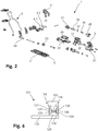
- the Figure 2 shows an exploded view of the automatic heel unit 1 in the downhill configuration in an oblique view.
- the automatic heel unit 1 is shown aligned so that the automatic heel unit 1 in the front Figure 2 is at the top left, while the automatic heel unit 1 is at the back in the Figure 2 bottom right is.
- Next are above and below the automatic heel unit 1 in the Figure 2 above and below.
- the base unit 2 comprises several elements.
- the base unit 2 thus comprises a base plate 21 which can be fastened to the ski.
- the base unit 2 further comprises a slide 22 which is mounted on the base plate 21 so as to be displaceable in the longitudinal direction of the ski.
- a longitudinal positioning arrangement is also located between the carriage 22 and the base plate 21.
- the longitudinal positioning arrangement includes, inter alia, a screw 23 which engages a half-thread on an upper side of the base plate 21, as well as a longitudinal compensation spring 24.
- the carriage 22 is also biased forward in a known manner together with the heel holder 3 by the longitudinal compensating spring 24 and can be pushed backwards against this bias in order to avoid changes in distance between the front-end automaton and the heel holder 3, which should occur when the Skis can arise to compensate.
- a vertically aligned pin 25 which is aligned concentrically with the pivot axis and which is formed from one piece together with the slide 22.
- This pin 25 is hollow on the inside and has two first recesses facing forwards and a second recess facing backwards in its lateral surface.
- a first pusher element 27 in the pin 25 is mounted on the peg 25 so as to be displaceable in the longitudinal direction of the ski
- a second pusher element 28 in the peg 25 is mounted on the peg 25 in the second recess so as to be displaceable in the longitudinal direction of the ski.
- An elastic element 26 is clamped between the first impact element 27 and the second impact element 28.
- the entire volume of the elastic element 26 is located in an inner volume of the pin 25. In other embodiments, however, there is also the possibility that, for example, only 70% or only 90% of the volume of the elastic element 26 is located in the inner volume of the pin 25.
- the elastic element 26 is a spiral spring which is aligned in the longitudinal direction of the ski. Since the elastic element 26 is clamped between the first pushing element 27 and the second pushing element 28, the elastic element 26 generates a forwardly directed first force due to which the first pushing element 27 is pushed forward. An alignment axis of the elastic element 26 aligned along the direction of the first force is thus aligned in the longitudinal direction of the ski and thus perpendicular to the pivot axis. At the same time, the elastic element 26 generates a rearwardly directed second force, as a result of which the second pushing element 28 is pressed backward. The bias of the elastic element 26 and thus a strength of the first force and a strength of the second force can be adjusted by means of an adjusting screw 35.
- the heel holder 3 is mounted on the pin 25 so as to be pivotable about the pin 25 and thus about the pivot axis.
- the heel holder 3 comprises a housing 31 which comprises two parts. These two parts of the housing 31 are screwed together in the assembled state of the automatic heel unit 1 and form a downwardly directed receptacle 32 into which the pin 25 is rotatably inserted.
- the pin 25 and the receptacle 32 thus form the radial bearing, by means of which the heel holder 3 is mounted on the base unit 2 such that it can pivot about the pivot axis relative to the base unit 2.
- the pivot axis runs concentrically through the pin 25 and through the receptacle 32.
- FIGs 3a and 3b each show a plan view of a horizontally oriented cross section through the automatic heel 1 at the level of the elastic element 26, the first pushing element 27 and the second pushing element 28.
- the automatic heel 1 is shown in FIG Figure 3a shown in the downhill configuration, where the heel holder 3 is in its holding position.
- the heel holder 3 is pivoted somewhat laterally to the left, starting from its holding position, so that the holding means 4.1, 4.2, which are not visible here, point to the front left.
- the first push element 27 comprises a first positioning structure 29 on its side facing away from the elastic element 26 and thus facing forward.
- the second impact element 28 comprises a second positioning structure 30 on its side facing away from the elastic element 26 and thus facing backwards.
- a first counter-structure 33 and a second counter-structure 34 are located opposite one another on the inside of the receptacle 32. The first counter-structure 33 is thus arranged in a first radial direction from the pivot axis, while the second counter-structure 34 is arranged in a second radial direction from the pivot axis that is opposite to the first radial direction.
- the first counter-structure 33 is located at the front on the inside of the receptacle 32, while the second counter-structure 34 is located at the rear on the inside of the receptacle 32.
- the elastic element 26 is clamped between the first pushing element 27 and the second pushing element 28. As a result, the elastic element 26 generates a forwardly directed first force due to which the first pushing element 27 is pushed forward, and a rearwardly directed second force due to which the second pushing element 28 is pushed backward.
- the first pushing element 27 with the first positioning structure 29 is thus pressed against the first counter-structure 33, while the second pushing element 28 with the second positioning structure 30 is pressed against the second counter-structure 34. Since the elastic element 26 acts directly on the first pushing element 27 with the first force, the first pushing element 27 is pressed with a first pushing element force, which is the same as the first force, with the first positioning structure 29 against the first counter-structure 33.
- the automatic heel unit comprises a first deflection mechanism or a first lever mechanism which effects a deflection and / or an increase or reduction of the first force into the first impact element force.
- the automatic heel unit comprises a second deflection mechanism or a second lever mechanism which effects a deflection and / or an increase or reduction of the second force into the second impact element force.
- the first deflecting mechanism or first lever mechanism that may be present and the second deflecting mechanism or second lever mechanism that may be present can also be a combined mechanism.
- the heel holder 3 can be pivoted on both sides about the pivot axis. As already mentioned, the heel holder 3 can thus be adjusted along the adjustment path.
- the heel holder 3 is in its holding position and if the heel holder 3 is pivoted somewhat about the pivot axis starting from its holding position on one of the two possible sides, the heel holder 3 is in a first area of the adjustment path. With such a pivoting movement of the heel holder 3 within the first range of the adjustment path, the first counter structure 33 is tilted relative to the first positioning structure 29, while at the same time the second counter structure 34 is tilted relative to the second positioning structure 30.
- the heel holder 3 is moved away from its holding position, the more the first pushing element 27 is moved towards the pivot axis against the bias of the elastic element 26 due to the shape of the first positioning structure 29 and the first counter-structure 33.
- the second pushing element 28 is moved further towards the pivot axis due to the shape of the second positioning structure 30 and the second counter-structure 34 against the bias of the elastic element 26.
- the heel holder 3 is therefore pretensioned towards its holding position within the first range of the adjustment path.
- the heel holder 3 can be pivoted away on both sides against this bias.
- the heel holder 3 can be pivoted away from its holding position against the bias in the event of lateral impacts on the ski, ski binding or ski boot. If the energy of a shock exceeds a limit value, the heel holder 3 can be pivoted sufficiently far about the pivot axis so that the ski boot is released on the corresponding side by the automatic heel unit 1.
- the automatic heel unit 1 thus enables a lateral safety release.
- the heel holder 3 If the heel holder 3 is pivoted laterally away from its holding position beyond the first range of the adjustment path, then the first pushing element 27 and the second pushing element 28 are no longer moved against the bias of the elastic element 26 towards the pivot axis. Only when the heel holder 3 is pivoted further does the heel holder 3 reach a second area of the adjustment path, where the first counter structure 33 has reached the second positioning structure 30 of the second push element 28 and the second counter structure 34 has reached the first positioning structure 29 of the first push element 27 has reached.
- the first pushing element 27 and the second pushing element 28 can be moved further apart again by the pretensioned elastic element 26 with increasing pivoting movement of the heel holder 3 until the heel holder 3 has reached its walking position, where it is compared to its holding position is pivoted relative to the base unit 2 by 180 ° about the pivot axis.
- the heel holder 3 is thus biased towards its walking position within the second region of the adjustment path.
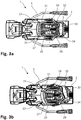
- FIGS 4a and 4b each show a view of a vertically oriented cross section running in the longitudinal direction of the ski through the automatic heel unit 1.
- the automatic heel unit 1 is shown in FIG Figure 4a shown in the departure configuration while in Figure 4b shown in the second walking configuration.
- the adjusting screw 35 can be rotated, whereby the nut 36 is moved along the adjusting screw 35 and the pretensioning of the elastic element 26 is adjusted. In this way, the energy that the automatic heel unit 1 can absorb until a lateral safety release occurs can be set.
- the pin 25 is hollow on the inside and has two first recesses oriented toward the front and a second recess oriented toward the rear in its outer surface.
- the first pusher element 27 and the second pusher element 28 extend out of the pin 25 through these recesses and can interact with their first positioning structure 29 and second positioning structure 30, as described above, with the first counter-structure 33 or with the second counter-structure 34.
- the pin 25 at its proximal end and at its distal end each have a rim that extends away from the pivot axis and overlaps the lateral surface.
- the housing 31 of the heel holder 3 engages around the upper rim and in the area of the lateral surface of the pin 25 extends somewhat towards the pivot axis to the lateral surface.
- the heel holder 3 is held on the pin 25 in the axial direction.
- the radial bearing formed from the journal 25 and the recess 32 also forms an axial bearing at the same time.
- the automatic heel unit has an axial bearing separated from the radial bearing.
- the axial bearing can be arranged in the radial direction outside or inside the radial bearing, for example, as seen from the pivot axis.
- the two holding means 4.1, 4.2 are formed by horizontally aligned pins, which point with their free ends forwards in order to engage in corresponding recesses in the heel area of the ski boot in order to lower the heel area of the ski boot Hold down position.
- the two holding means 4.1, 4.2 are pretensioned towards one another and can be pressed apart against this pretensioning, whereby the automatic heel unit 1 enables a safety release in the forward direction.
- the mechanism by which this pretension is generated is arranged in the heel holder 3 above the pin 25.
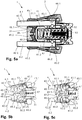
- FIGs 5a, 5b and 5c each show a bottom view of a horizontally aligned cross-section through the heel holder 3 of the automatic heel unit 1 at the level of the mechanism by which the prestress is generated with which the two holding means 4.1, 4.2 are prestressed towards one another.
- the two holding means 4.1, 4.2 are each shown with their free ends pointing to the left in the figures. If the automatic heel 1 is thus in the downhill configuration and the heel holder 3 is in its holding position and the free ends of the two holding means 4.1, 4.2 thus point forward, then the automatic heel 1 is at the front left in the illustration, while the automatic heel 1 at the back of the illustration on the right.
- the cross section shown runs through the two holding means 4.1, 4.2.
- the cross-section runs at a height slightly below the two holding means 4.1, 4.2 through the heel holder 3.
- the two holding elements 42.1, 42.2 are shown at a holding distance from one another, while the two holding elements 42.1, 42.2 in the Figure 5c are shown moved away from each other by their holding distance.
- the two holding means 4.1, 4.2 are formed by horizontally aligned pins which, in the holding position of the heel holder 3, point with their free ends forward in order to engage in corresponding recesses in the heel area of the ski boot.
- the two holding means 4.1, 4.2 or the two pins can each be divided into an arm 41.1, 41.2 and a holding element 42.1, 42.2 for holding the ski boot in the heel area of the ski boot, the respective holding element 42.1, 42.2 at a holding end of the respective Arms 41.1, 41.2 is arranged.
- the formulation also applies, according to which the two holding elements 42.1, 42.2 are each formed by a pin with its free end pointing forwards in order to engage in a recess in the heel area of the ski boot to hold the ski boot in the heel area of the ski boot.
- the two holding means 4.1, 4.2 are each pivotably mounted on the remainder of the heel holder 3 in an area of an end of the respective arm 41.1, 41.2 opposite the holding end of the respective arm 41.1, 41.2.
- the pins are each held in the area of the end of the respective arm 41.1, 41.2 opposite the holding end of the respective arm 41.1, 41.2 in the housing 31 of the heel holder 3 in the directions perpendicular to the longitudinal axis of the respective arm 41.1, 41.2.
- the pins each have a circumferential groove 44.1, 44.2 in the area of the end of the respective arm 41.1, 41.2 opposite the holding end of the respective arm 41.1, 41.2, with a vertical bolt 43.1 for each holding means 4.1, 4.2 when the automatic heel unit 1 is assembled , 43.2 is inserted in the housing 31 of the heel holder 3, which runs through the groove 44.1, 44.2 in the respective arm 41.1, 41.2 and thereby the respective holding means 4.1, 4.2 on a movement of the respective holding means 4.1, 4.2 in the longitudinal direction of the arm 41.1, 41.2 of the respective holding means 4.1, 4.2 prevents.
- the two holding means 4.1, 4.2 each in a region of the end of the respective arm 42.1, 42.2 opposite the holding end of the respective arm 41.1, 41.2 mounted pivotably relative to one another on the remaining heel holder 3, whereby a distance between the two holding elements 42.1, 42.2 can be changed.
- the two holding means 4.1, 4.2 are each mounted on the remaining heel holder 3 so that they can rotate about the longitudinal axis of the respective arm 41.1, 41.2.
- the automatic heel unit 1 further comprises a transmission element 46 arranged in the housing 31 of the heel holder 3 and an elastic pretensioning element 47 also arranged in the housing 31 of the heel holder 3
- Holding means 4.1, 4.2 each have a sleeve 45.1, 45.2.
- the elastic preloading element 47 is designed in the form of a spiral spring and is supported at a first end against a nut 52. This nut 52 is screwed onto a screw 53, which in turn is supported on an inner side of the housing 31 of the heel holder 3. A position of the first end of the elastic prestressing element 47 within the housing 31 of the heel holder 3 can thus be adjusted by turning the screw 53. This enables a pre-tensioning of the elastic pre-tensioning element 47 to be adjusted because the elastic pre-tensioning element 47 is also supported at a second end against the transmission element 46.
- the elastic prestressing element 47 therefore presses against the transmission element 46 with a prestressing force dependent on the prestressing of the elastic prestressing element 47. Due to this prestressing force, the transmission element 46 acts with the prestressing force on the two sleeves 45.1, 45.2.
- the two sleeves 45.1, 45.2 are each mounted on the arm 41.1, 41.2 of the respective holding means 4.1, 4.2 in a region of the holding end of the respective arm 41.1, 41.2 in the longitudinal direction of the respective arm 41.1, 41.2.
- the two sleeves 45.1, 45.2 are mounted horizontally in the transverse direction of the ski in the housing 31 of the heel holder 3. Because of this mounting of the sleeves 45.1, 45.2 and because of the pivoting mounting of the arms 41.1, 41.2, the two holding means 4.1, 4.2 are mounted so as to be movable relative to one another in a horizontal plane.
- both sleeves 45.1, 45.2 each have a first control structure 48.1, 48.2 facing the holding element 42.1, 42.2 of the respective holding means 4.1, 4.2.
- These first control structures 48.1, 48.2 are inclined with respect to the longitudinal directions of the arms 41.1, 41.2 and run towards the center of the ski in the direction of the holding elements 42.1, 42.2.
- first control structures 48.1, 48.2 face first counter-control structures 49.1, 49.2, which are arranged on an inside of a wall of the housing 31 of the heel holder 3 facing the holding elements 42.1, 42.2 and which are also inclined to the longitudinal directions of the arms 41.1, 41.2 and to the center of the ski extend towards the retaining elements 42.1, 42.2. Since the elastic prestressing element 47 is aligned parallel to the arms 41.1, 41.2, the elastic prestressing element 47 presses the transmission element 46 with the prestressing force against the two sleeves 45.1, 45.2, whereby the sleeves 45.1, 45.2 with their first control structures 48.1, 48.2 against the first Control counter structures 49.1, 49.2 on the housing 31 of the heel holder 3 are pressed.
- the two sleeves 45.1, 45.2 are pretensioned towards one another.
- the two holding ends of the arms 41.1, 41.2 are biased towards each other with the sleeves 45.1, 45.2, whereby the two holding elements 42.1, 42.2 are biased towards each other with the holding force to their holding distance so that the two holding means 4.1, 4.2 in the holding configuration of Automatic heel units 1 interact with the heel area of the ski boot held in the ski binding and can hold down the heel area of the ski boot in the lowered position and thus the automatic heel unit 1 enables a safety release in the forward direction.
- the two sleeves 45.1, 45.2 each have a second control structure 50.1, 50.2 facing away from the holding element 42.1, 42.2 of the respective holding means 4.1, 4.2.
- These second control structures 50.1, 50.2 are inclined with respect to the longitudinal directions of the arms 41.1, 41.2 and run away from the holding elements 42.1, 42.2 towards the center of the ski.
- These second control structures 50.1, 50.2 face second counterpart control structures 51.1, 51.2, which are arranged on the transmission element 47 and also opposite one another are inclined in the longitudinal directions of the arms 41.1, 41.2 and run away from the holding elements 42.1, 42.2 towards the center of the ski.
- the two sleeves 45.1, 45.2 are thus not only through an interaction of the first control structures 48.1, 48.2 with the first counter control structures 49.1, 49.2, but also through an interaction of the second control structures 50.1, 50.2 with the second counter control structures 51.1, 51.2 biased towards one another.
- the holding ends of the arms 41.1, 41.2 are thus pretensioned towards one another, whereby the two holding elements 42.1, 42.2 are pretensioned towards one another with the holding force to their holding distance.
- the two holding elements 42.1, 42.2 are accordingly located as in FIG Figures 5a and 5b shown in their holding distance from one another when the two holding elements 42.1, 42.2 are not pressed apart by an external force.
- the two holding elements 42.1, 42.2 are not only pretensioned with the holding force to their holding distance, but are also as in FIG Figure 5c shown against the holding force of their holding distance apart and thus movable away from their holding distance.
- the two holding elements 42.1, 42.2 for entry into the automatic heel unit 1 can be moved apart from their holding distance when a ski boot for entry into the automatic heel unit 1 is guided from top to bottom over the holding means 4.1, 4.2.
- the two holding elements 42.1, 42.2 can also be moved apart from their holding distance against the holding force, if an upward force on the ski boot or a downward force on the automatic heel unit 1 or the ski is sufficiently great to move the ski boot to be released from the automatic heel 1 for a safety release in the forward direction.
- a release value of this safety release can be set in the forward direction because the pretensioning force and thus also the holding force can be adjusted by adjusting the screw 53.
- Both entry into the automatic heel unit 1 and a safety release in the forward direction are also optimally controlled because the arms 41.1, 41.2 of the two holding means 4.1, 4.2 are each rotatable about the longitudinal axis of the respective arm 41.1, 41.2 remaining heel holder 3 and rotatably mounted in the respective sleeve 45.1, 45.2, whereby frictional resistance of the ski boot on the holding means 4.1, 4.2 are minimized.
- FIG. 6 shows a simplified schematic side view of a further automatic heel 101 according to the invention.
- This automatic heel 101 is essentially the same as that in FIG Figures 1a to 5
- the automatic heel unit 1 shown is constructed and comprises a base unit 102 for attachment to the surface of a ski, a heel holder 103 with at least one holding means 104 and a radial bearing through which the heel holder 103 can be pivoted about a vertically oriented, geometric pivot axis relative to the base unit 102 on the base unit 102 is stored.
- the automatic heel unit 101 also comprises an elastic element 126 arranged in the pin 125, the alignment axis of which is aligned perpendicular to the pivot axis.
- a first pusher element 127 and a second pusher element 128 are again mounted displaceably in the pin 125, the elastic element 126 being clamped between the first pusher element 127 and the second pusher element 128.
- the pin 125 is arranged on the heel holder 103, while the receptacle 132 is arranged on the base unit 102.
- the first counter structure 133 and the second counter structure 134 are assigned to the heel holder 103, while the first positioning structure 129 is still arranged on the first push element 127 and the second positioning structure 130 is still arranged on the second push element 128.
- the base unit can be designed differently, for example in one piece.
- the heel holder can also be designed differently.
- a jaw can also be used as the holding means.
- the radial bearing also forms an axial bearing.
- the automatic heel unit can also comprise an axial bearing that is embodied separately from the radial bearing.
- an automatic heel unit which has a compact design and at the same time enables the heel holder to be stably supported on the base element.
Abstract
Die Erfindung betrifft einen Fersenautomaten (1) für eine Skibindung, insbesondere eine Tourenskibindung, umfassend einen Fersenhalter (3) mit zwei Haltemitteln (4.1, 4.2) zum Halten eines Skischuhs in einem Fersenbereich des Skischuhs, ein vorspannbares elastisches Vorspannelement (47) zum Erzeugen einer Vorspannkraft und ein Übertragungselement (46) zum Übertragen der Vorspannkraft, wobei der Fersenautomat (1) eine Abfahrtskonfiguration aufweist, in welcher sich der Fersenhalter (3) in einer Haltestellung befindet und die beiden Haltemittel (4.1, 4.2) mit dem Fersenbereich des in der Skibindung gehaltenen Skischuhs derart zusammenwirken können, dass der Fersenbereich des Skischuhs in einer abgesenkten Position niedergehalten ist. Dabei weisen die zwei Haltemittel (4.1, 4.2) je einen Arm (41.1, 41.2) mit einem Halteende sowie ein am Halteende des jeweiligen Arms (41.1, 41.2) angeordnetes Halteelement (42.1, 42.2) zum Halten des Skischuhs im Fersenbereich des Skischuhs auf. Die beiden Haltemittel (4.1, 4.2, 104) sind relativ zueinander bewegbar, wodurch ein Abstand zwischen den beiden Halteelementen (42.1, 42.2) veränderbar ist, wobei die beiden Halteelemente (42.1, 42.2) mit einer Haltekraft zu einem Halteabstand zueinander vorspannbar sind, um in der Haltekonfiguration des Fersenautomaten (1) mit dem Fersenbereich des in der Skibindung gehaltenen Skischuhs zusammenzuwirken und den Fersenbereich des Skischuhs in der abgesenkten Position niederzuhalten. Dabei weist jedes Haltemittel (4.1, 4.2) eine entlang des Arms des jeweiligen Haltemittels (4.1, 4.2) verschiebbare Hülse (45.1, 45.2) auf, wobei das Übertragungselement (46) aufgrund der vom elastischen Vorspannelement (47) erzeugten Vorspannkraft gegen die Hülsen (45.1, 45.2) der beiden Haltemittel (4.1, 4.2) drückbar ist, um die beiden Halteelemente (42.1, 42.2) mit der Haltekraft zu ihrem Halteabstand vorzuspannen, wobei die Hülsen (45.1, 45.2) je eine erste Steuerstruktur (48.1, 48.2) aufweisen, welche je mit einer ersten Steuergegenstruktur (49.1, 49.2) des Fersenhalters (3) zusammenwirken, wobei die Hülsen (45.1, 45.2) mit ihren ersten Steuerstrukturen (48.1, 48.2) durch das Übertragungselement (46) aufgrund der vom elastischen Vorspannelement (47) erzeugten Vorspannkraft gegen die ersten Steuergegenstrukturen (49.1, 49.2) gedrückt werden, um die beiden Halteelemente (42.1, 42.2) mit der Haltekraft zu ihrem Halteabstand vorzuspannen.The invention relates to an automatic heel unit (1) for a ski binding, in particular a touring ski binding, comprising a heel holder (3) with two holding means (4.1, 4.2) for holding a ski boot in a heel area of the ski boot, a pretensionable elastic pretensioning element (47) for producing a Pre-tensioning force and a transmission element (46) for transmitting the pre-tensioning force, the automatic heel unit (1) having a descent configuration in which the heel holder (3) is in a holding position and the two holding means (4.1, 4.2) with the heel area of the ski binding held ski boot can interact in such a way that the heel area of the ski boot is held down in a lowered position. The two holding means (4.1, 4.2) each have an arm (41.1, 41.2) with a holding end and a holding element (42.1, 42.2) arranged at the holding end of the respective arm (41.1, 41.2) for holding the ski boot in the heel area of the ski boot. The two holding means (4.1, 4.2, 104) can be moved relative to one another, whereby a distance between the two holding elements (42.1, 42.2) can be changed, the two holding elements (42.1, 42.2) being pretensioned with a holding force to a holding distance from one another in order to in the holding configuration of the automatic heel unit (1) to interact with the heel area of the ski boot held in the ski binding and to hold down the heel area of the ski boot in the lowered position. Each holding means (4.1, 4.2) has a sleeve (45.1, 45.2) which can be displaced along the arm of the respective holding means (4.1, 4.2), the transmission element (46) against the sleeves (46) due to the prestressing force generated by the elastic prestressing element (47). 45.1, 45.2) of the two holding means (4.1, 4.2) can be pressed in order to pretension the two holding elements (42.1, 42.2) with the holding force to their holding distance, the sleeves (45.1, 45.2) each having a first control structure (48.1, 48.2) which each cooperate with a first control counter structure (49.1, 49.2) of the heel holder (3), the sleeves (45.1, 45.2) with their first control structures (48.1, 48.2) being carried by the transmission element (46) due to the elastic biasing element (47) generated biasing force are pressed against the first control counter structures (49.1, 49.2) in order to bias the two holding elements (42.1, 42.2) with the holding force to their holding distance.
Description
Die Erfindung betrifft einen Fersenautomaten für eine Skibindung, insbesondere eine Tourenskibindung. Dieser Fersenautomat umfasst eine Basiseinheit zur Befestigung auf der Oberfläche eines Skis und einen Fersenhalter mit wenigstens einem Haltemittel zum Halten eines Skischuhs in einem Fersenbereich des Skischuhs, wobei der Fersenautomat eine Abfahrtskonfiguration aufweist, in welcher sich der Fersenhalter in einer Haltestellung befindet und das wenigstens eine Haltemittel mit dem Fersenbereich des in der Skibindung gehaltenen Skischuhs derart zusammenwirken kann, dass der Fersenbereich des Skischuhs in einer abgesenkten Position niedergehalten ist. Weiter umfasst der Fersenautomat ein Radiallager, durch welches der Fersenhalter um eine im Wesentlichen vertikal ausgerichtete, geometrische Schwenkachse relativ zur Basiseinheit schwenkbar an der Basiseinheit gelagert ist und damit ausgehend von seiner Haltestellung entlang eines Verstellwegs um die Schwenkachse von seiner Haltestellung weg schwenkbar ist, wobei das Radiallager einen Zapfen aufweist, welcher an einer ersten der beiden Einheiten aus Basiseinheit und Fersenhalter ausgebildet ist, und das Radiallager eine Aufnahme aufweist, welche an einer zweiten der beiden Einheiten aus Basiseinheit und Fersenhalter ausgebildet ist, wobei der Zapfen drehbar in die Aufnahme eingesetzt ist, wodurch der Fersenhalter um die Schwenkachse relativ zur Basiseinheit schwenkbar an der Basiseinheit gelagert ist. Ausserdem umfasst der Fersenautomat eine Vorspanneinrichtung, durch welche der Fersenhalter in einem ersten Bereich des Verstellwegs zu seiner Haltestellung hin vorspannbar ist, wobei die Vorspanneinrichtung ein erstes Stosselement mit einer ersten Positionierstruktur und ein elastisches Element umfasst, wobei das erste Stosselement aufgrund einer vom elastischen Element erzeugten und entlang einer Ausrichtungsachse des elastischen Elements in eine erste Richtung ausgerichteten ersten Kraft mit der ersten Positionierstruktur gegen eine erste Gegenstruktur drückbar ist, wenn sich der Fersenhalter im ersten Bereich des Verstellwegs befindet, um den Fersenhalter im ersten Bereich des Verstellwegs zu seiner Haltestellung hin vorzuspannen.The invention relates to an automatic heel unit for a ski binding, in particular a touring ski binding. This automatic heel unit comprises a base unit for fastening on the surface of a ski and a heel holder with at least one holding means for holding a ski boot in a heel area of the ski boot, the automatic heel unit having a descent configuration in which the heel holder is in a holding position and the at least one holding means can interact with the heel area of the ski boot held in the ski binding in such a way that the heel area of the ski boot is held down in a lowered position. Furthermore, the automatic heel unit comprises a radial bearing, by means of which the heel holder is mounted on the base unit so as to be pivotable about a substantially vertically aligned, geometric pivot axis relative to the base unit and can thus be pivoted away from its holding position starting from its holding position along an adjustment path around the pivot axis Radial bearing has a pin which is formed on a first of the two units of base unit and heel holder, and the radial bearing has a receptacle which is formed on a second of the two units of base unit and heel holder, wherein the pin is rotatably inserted into the receptacle, whereby the heel holder is pivotably mounted on the base unit about the pivot axis relative to the base unit. In addition, the automatic heel unit comprises a pretensioning device, by means of which the heel holder can be pretensioned towards its holding position in a first area of the adjustment path, the pretensioning device comprising a first pushing element with a first positioning structure and an elastic element, the first pushing element being generated by the elastic element and along an alignment axis of the elastic element in a first direction aligned first force with the first positioning structure can be pressed against a first counter structure when the heel holder is located in the first region of the adjustment path to preload the heel holder in the first region of the adjustment path towards its holding position.
Fersenautomaten des eingangs genannten technischen Gebiets sind bekannt. Sie haben die Aufgabe, in einer Abfahrtskonfiguration eine zuverlässige Fixierung des Fersenbereichs des Skischuhs auf dem Ski zu gewährleisten. Um die Sicherheit des Skifahrers zu erhöhen, ermöglichen einige solche Fersenautomaten zudem ausgehend aus der Abfahrtskonfiguration eine Sicherheitsauslösung, bei welcher der Fersenbereich des Skischuhs freigegeben wird. Dabei kann es sich beispielsweise um eine Sicherheitsauslösung in Vorwärtsrichtung oder um eine seitliche Sicherheitsauslösung handeln. In beiden Fällen bedeutet der Begriff "Sicherheitsauslösung", dass der Fersenautomat den Fersenbereich des Skischuhs freigibt, falls die Energie eines Stosses auf den Skischuh, die Skibindung oder den Ski einen vorbestimmten Wert überschreitet. Dabei ist unerheblich, ob sich der Fersenautomat nach der Freigabe des Skischuhs in der Abfahrtskonfiguration oder in einer anderen Konfiguration befindet. Bei Stössen, deren Energie diesen Wert nicht überschreiten, verbleibt der Fersenautomat in der Abfahrtskonfiguration und behält den Fersenbereich des Skischuhs weiterhin in einer zum Ski hin abgesenkten Position arretiert.Automatic heel units in the technical field mentioned above are known. Their task is to ensure that the heel area of the ski boot is reliably fixed on the ski in a downhill configuration. In order to increase the safety of the skier, some such automatic heel machines also enable a safety release based on the descent configuration, in which the heel area of the ski boot is released. This can be, for example, a safety release in the forward direction or a lateral safety release. In both cases, the term “safety release” means that the automatic heel unit releases the heel area of the ski boot if the energy of an impact on the ski boot, ski binding or ski exceeds a predetermined value. It is irrelevant whether the automatic heel is in the downhill configuration or in another configuration after the ski boot has been released. In the event of impacts whose energy does not exceed this value, the automatic heel unit remains in the downhill configuration and keeps the heel area of the ski boot locked in a position lowered towards the ski.
Weiter hängt die Art der von einem Fersenautomaten zu übernehmenden Aufgaben in der Regel davon ab, welche Funktion die Skibindung, zu welcher der Fersenautomat gehört, erfüllen soll. Abfahrtsskibindungen beispielsweise werden nur zum Abfahren und Skifahren an Skiliften verwendet. Dagegen werden Tourenskibindungen zusätzlich auch zum Gehen auf Skiern, insbesondere zum Aufsteigen mit Hilfe von an den Skiern befestigten Steigfellen, verwendet. Langlaufbindungen hingegen werden zum Langlaufen und Telemarkbindungen zum Skifahren mit der Telemark-Technik verwendet. Von diesen Skibindungen haben Abfahrtsskibindungen bloss eine zuverlässige Fixierung des Skischuhs auf dem Ski in einer sogenannten Halteposition zu gewährleisten. Einige Fersenautomaten weisen zudem eine sogenannte Einstiegskonfiguration oder Auslösekonfiguration auf, in welcher sie einen Einstieg in die Skibindung ermöglichen. Diese Funktion kann aber auch von einem Frontautomaten übernommen werden. Demgegenüber haben Langlauf- sowie Telemarkbindungen in der Regel den Skischuh bloss um eine in Skiquerrichtung ausgerichtete Achse schwenkbar zu halten sowie den Einstieg in die Skibindung zu ermöglichen. Dahingegen müssen Tourenskibindungen wie Abfahrtsskibindungen eine zuverlässige Fixierung des Skischuhs auf dem Ski in der Halteposition gewährleisten sowie einen Einstieg in die Skibindung ermöglichen. Zusätzlich müssen sie aber zum Gehen auf Skiern beziehungsweise für den Aufstieg den Skischuh um eine horizontal in Skiquerrichtung ausgerichtete Achse schwenkbar halten können. Hierzu weisen Tourenskibindungen eine Gehposition auf, in welcher der Skischuh wie bei Langlauf- und Telemarkbindungen um eine horizontal in Skiquerrichtung ausgerichtete Achse verschwenkbar und im Fersenbereich vom Ski abhebbar ist, wodurch zum Gehen eine Gelenkbewegung zwischen dem Skischuh und dem Ski ermöglicht wird. Da es verschiedene Konstruktionsweisen und Typen von Tourenskibindungen gibt, kann sich der Fersenautomat in der Gehposition einer Tourenskibindung je nach Konstruktion und Typ der Tourenskibindung in unterschiedlichen Konfigurationen befinden. So kann er sich beispielsweise in seiner Abfahrtskonfiguration, in einer Einstiegskonfiguration, in einer Auslösekonfiguration oder in einer Gehkonfiguration befinden.Furthermore, the type of tasks to be performed by an automatic heel device generally depends on which function the ski binding to which the automatic heel device belongs is to fulfill. Downhill ski bindings, for example, are only used for downhill skiing and skiing on ski lifts. On the other hand, touring ski bindings are also used for walking on skis, in particular for climbing with the help of climbing skins attached to the skis. Cross-country bindings, on the other hand, are used for cross-country skiing and telemark bindings for skiing with the telemark technique. Of these ski bindings, downhill ski bindings only have to ensure a reliable fixation of the ski boot on the ski in a so-called holding position. Some automatic heel machines also have a so-called entry configuration or release configuration, in which they enable entry into the ski binding. However, this function can also be taken over by a front machine. In contrast, cross-country and telemark bindings generally only have to keep the ski boot pivotable about an axis oriented in the transverse direction of the ski and to allow entry into the ski binding enable. On the other hand, touring ski bindings such as downhill ski bindings must ensure reliable fixation of the ski boot on the ski in the holding position and enable entry into the ski binding. In addition, however, they must be able to hold the ski boot pivotably about an axis aligned horizontally in the transverse direction of the ski for walking on skis or for climbing. For this purpose, touring ski bindings have a walking position in which the ski boot, like cross-country and telemark bindings, can be pivoted about an axis oriented horizontally in the transverse direction of the ski and can be lifted off the ski in the heel area, which enables a joint movement between the ski boot and the ski for walking. Since there are different construction methods and types of touring ski bindings, the automatic heel can be in the walking position of a touring ski binding in different configurations depending on the construction and type of touring ski binding. For example, he can be in his departure configuration, in an entry configuration, in a release configuration or in a walking configuration.
Falls bei einer Langlauf- und Telemarkbindung zusätzlich eine Halteposition gewünscht ist, so ist bei einer solchen Langlauf- beziehungsweise Telemarkbindung zusätzlich ein Fersenautomat erforderlich, mittels welchem der Skischuh in seinem Fersenbereich zum Ski hin abgesenkt arretiert werden kann, und welcher den Fersenbereich des Skischuhs zum Gehen in der Gehposition der Langlauf- beziehungsweise Telemarkbindung freigeben kann.If a holding position is also required for cross-country and telemark bindings, a heel machine is also required for such a cross-country or telemark binding, by means of which the ski boot can be locked in its heel area towards the ski, and which the heel area of the ski boot can be used for walking in the walking position of the cross-country or telemark binding.
Tourenskibindungen sind grundsätzlich in zwei Typen unterteilbar. Der eine Typ umfasst einen gegenüber dem Ski verschwenkbaren Skischuhträger, an welchem der Skischuh durch Bindungsbacken gehalten ist. Ein repräsentatives Mitglied dieses Typs von Tourenskibindungen ist beispielsweise in der
Es versteht sich, dass bei diesem zweiten Typ von Tourenskibindungen der Abstand, in welchem der Fersenautomat vom Frontautomaten am Ski montiert werden muss, durch die Länge der Sohle des zu haltenden Skischuhs diktiert ist.It goes without saying that in this second type of touring ski bindings, the distance at which the automatic heel device must be mounted on the ski by the automatic front device is dictated by the length of the sole of the ski boot to be held.
Für die Beschreibung von derartigen Bindungssystemen wird als Referenzsystem oft ein (fiktiver) Ski verwendet, wobei angenommen wird, dass die Bindung auf diesem Ski montiert sei. Diese Gewohnheit wird im vorliegenden Text übernommen. So bedeutet der Begriff "Skilängsrichtung" entlang der Ausrichtung der Längsachse des Skis. Ähnlich bedeutet "skiparallel" für ein längliches Objekt entlang der Längsachse des Skis ausgerichtet. Für ein flächiges Objekt hingegen bedeutet der Begriff "skiparallel" parallel zur Gleitfläche des Skis ausgerichtet. Weiter ist mit dem Begriff "Skiquerrichtung" eine Richtung quer zur Skilängsrichtung gemeint, welche aber nicht genau rechtwinklig zur Längsachse des Skis orientiert sein muss. Ihre Ausrichtung kann auch etwas von einem rechten Winkel abweichen. Der Begriff "Skimitte" wiederum bedeutet in Skiquerrichtung gesehen eine Mitte des Skis, während der Begriff "skifest" nicht beweglich gegenüber dem Ski bedeutet. Zudem ist zu beachten, dass auch Begriffe, welche das Wort "Ski" nicht enthalten, auf das Referenzsystem des (fiktiven) Skis Bezug nehmen. So beziehen sich die Begriffe "vorne", "hinten", "oben", "unten" sowie "seitlich" auf "vorne", "hinten", "oben", "unten" sowie "seitlich" des Skis. Genauso beziehen sich auch Begriffe wie "horizontal" und "vertikal" auf den Ski, wobei "horizontal" in einer skiparallelen Ebene liegend und "vertikal" senkrecht zu dieser Ebene ausgerichtet bedeutet.A (fictitious) ski is often used as a reference system to describe such binding systems, it being assumed that the binding is mounted on this ski. This habit is taken over in the present text. The term "longitudinal direction of the ski" means along the alignment of the longitudinal axis of the ski. Similarly, "parallel to the ski" means oriented along the longitudinal axis of the ski for an elongate object. For a flat object, however, the term "parallel to the ski" means aligned parallel to the sliding surface of the ski. Furthermore, the term "transverse direction of the ski" means a direction transverse to the longitudinal direction of the ski, which, however, does not have to be oriented precisely at right angles to the longitudinal axis of the ski. Their orientation can also deviate slightly from a right angle. The term “ski center” in turn means a center of the ski, seen in the transverse direction of the ski, while the term “ski fixed” means not movable with respect to the ski. It should also be noted that terms that do not contain the word "ski" also refer to the reference system of the (fictitious) ski. The terms “front”, “rear”, “top”, “bottom” and “side” refer to “front”, “back”, “top”, “bottom” and “side” of the ski. In the same way, terms such as “horizontal” and “vertical” also relate to the ski, where “horizontal” means lying in a plane parallel to the ski and “vertical” means oriented perpendicular to this plane.
Eine Tourenskibindung des oben eingeführten, zweiten Typs ist in der
Ein vom Frontautomaten separater Fersenautomat dieses Systems weist ein Basiselement zur Befestigung auf einem Ski sowie einen Fersenhalter zum Halten des Skischuhs im Fersenbereich des Skischuhs auf. Der Fersenhalter ist auf einem am Basiselement angeordneten, vertikal ausgerichteten Zapfen gelagert und dadurch um eine vertikal ausgerichtete, geometrische Schwenkachse relativ zum Basiselement schwenkbar am Basiselement gelagert. In der Abfahrtskonfiguration des Fersenautomaten befindet sich der Fersenhalter in einer Haltestellung. In dieser Haltestellung sind zwei am Fersenhalter angeordnete Stifte nach vorne zum Frontautomaten hin ausgerichtet, wodurch sie in Ausnehmungen in der Ferse des Skischuhs eingreifen und dadurch den Skischuh in einer zum Ski hin abgesenkten Position arretieren können. Beim Einstieg in die Tourenskibindung wird der Skischuh zuerst im Frontautomaten gelagert. Danach wird die Ferse des Skischuhs von oben her auf die Stifte des Fersenhalters abgesenkt. Da die Ausnehmungen in der Ferse des Skischuhs nach unten weitgehend offen sind, werden dadurch die Ausnehmungen über die Stifte geführt, worauf die Stifte zur Verriegelung in Rastmulden in den Ausnehmungen einrasten.A heel machine of this system, which is separate from the front machine, has a base element for attachment to a ski and a heel holder for holding the ski boot in the heel area of the ski boot. The heel holder is mounted on a vertically oriented pin arranged on the base element and is thereby mounted on the base element so as to be pivotable about a vertically oriented, geometric pivot axis relative to the base element. In the downhill configuration of the automatic heel unit, the heel holder is in a holding position. In this holding position, two pins arranged on the heel holder are oriented towards the front automaton, whereby they can engage in recesses in the heel of the ski boot and thereby lock the ski boot in a position lowered towards the ski. When getting into touring ski bindings, the ski boot is first stored in the front machine. Then the heel of the ski boot is lowered onto the pins of the heel holder from above. Since the recesses in the heel of the ski boot are largely open at the bottom, the recesses are thereby guided over the pins, whereupon the pins snap into locking recesses in the recesses.
Um eine Sicherheitsauslösung in Vorwärtsrichtung zu gewährleisten, können die beiden Stifte gegen eine Federkraft auseinandergedrückt werden, wodurch sie aus den Rastmulden und den Ausnehmungen gleiten und die Ferse des Skischuhs nach oben freigeben können. Dazu sind beide Stifte je an einem Hebel angeordnet, wobei die Hebel je in einer horizontalen Ebene schwenkbar am Fersenhalter gelagert sind. Beide Hebel sind mit einer Federkraft vorgespannt, so dass die beiden Stifte zueinander hin gedrückt werden. Durch Verstellen der Federkraft kann die Kraft vorgegeben werden, welche benötigt wird, um eine Auslösung in Vorwärtsrichtung zu ermöglichen. Dadurch wird eine Sicherheitsauslösung in Vorwärtsrichtung ermöglicht.In order to ensure a safety release in the forward direction, the two pins can be pressed apart against a spring force, whereby they slide out of the locking depressions and the recesses and can release the heel of the ski boot upwards. For this purpose, both pins are each arranged on a lever, the levers each being mounted on the heel holder so that they can pivot in a horizontal plane. Both levers are preloaded with a spring force, so that the two pins are pressed towards each other. By adjusting the spring force, the force can be specified which is required to enable forward tripping. This enables a safety release in the forward direction.
Nebst der Sicherheitsauslösung in Vorwärtsrichtung ermöglicht der Fersenautomat auch eine seitliche Sicherheitsauslösung. Hierzu kann der Fersenhalter um eine vertikal ausgerichtete, geometrische Schwenkachse gegen eine Federkraft auf beide Seiten geschwenkt werden, bis die beiden Stifte zur Seite weggeschwenkt sind und der Fersenbereich des Skischuhs zur entsprechenden Seite freigegeben ist. Um eine solche seitliche Sicherheitsauslösung zu ermöglichen, weist der Zapfen des Basiselements auf seiner hinteren Seite eine ebene Fläche auf, welche mit ihrem Normalenvektor horizontal nach hinten ausgerichtet ist. Ein im Fersenhalter gelagerter und mit einer Feder nach vorne vorgespannter Kolben wird in der Haltestellung gegen diese Fläche des Zapfens gedrückt. Wenn der Fersenhalter ausgehend von seiner Haltestellung um die Schwenkachse auf eine der beiden Seiten weggeschwenkt wird, so wird der Kolben mitgeschwenkt und gegenüber der Fläche des Zapfens verkippt. Dadurch wird der Kolben nach hinten gegen die Federkraft bewegt. Somit ist der Fersenhalter aufgrund der Federkraft zu seiner Haltestellung hin vorgespannt. Dabei kann durch Einstellung der Vorspannung der Feder der Wert vorgegeben werden, welcher von der Energie eines Stosses auf den Ski, die Skibindung oder den Ski überschritten werden muss, damit es zu einer seitlichen Sicherheitsauslösung kommt.In addition to the safety release in the forward direction, the automatic heel unit also enables a lateral safety release. For this purpose, the heel holder can be pivoted around a vertically aligned, geometric pivot axis against a spring force on both sides until the two pins are pivoted to the side and the heel area of the ski boot is released on the corresponding side. In order to enable such a lateral safety release, the pin of the base element has a flat surface on its rear side, which is aligned horizontally to the rear with its normal vector. A piston mounted in the heel holder and pretensioned forwards by a spring is pressed against this surface of the pin in the holding position. When the heel holder is pivoted away from its holding position about the pivot axis on one of the two sides, the piston is pivoted with it and tilted relative to the surface of the pin. This moves the piston backwards against the spring force. The heel holder is thus biased towards its holding position due to the spring force. By setting the preload of the spring, the value can be specified which must be exceeded by the energy of an impact on the ski, ski binding or ski so that a lateral safety release occurs.
Ein Fersenautomat gemäss der
Der Fersenautomat gemäss der
Aufgabe der Erfindung ist es, ein dem eingangs genannten technischen Gebiet zugehörender Fersenautomat zu schaffen, welcher kompakt konstruiert ist und zugleich eine stabile Lagerung des Fersenhalters auf dem Basiselement ermöglicht.The object of the invention is to create an automatic heel unit belonging to the technical field mentioned at the beginning, which is of compact construction and at the same time enables the heel holder to be stably supported on the base element.
Die Lösung der Aufgabe ist durch die Merkmale des Anspruchs 1 definiert. Gemäss der Erfindung ist das elastische Element im Zapfen angeordnet, wobei die Ausrichtungsachse des elastischen Elements senkrecht zur Schwenkachse ausgerichtet ist, und wobei die erste Gegenstruktur der zweiten der beiden Einheiten aus Basiseinheit und Fersenhalter zugeordnet ist.The solution to the problem is defined by the features of
Für die erfindungsgemässe Lösung ist unerheblich, wie die Basiseinheit genau ausgebildet ist. So kann die Basiseinheit einstückig oder mehrstückig ausgebildet sein. Beispielsweise kann die Basiseinheit wie beim Fersenautomaten der
Für die erfindungsgemässe Lösung ist unerheblich, wie der Fersenhalter genau ausgebildet ist. Der Fersenhalter bildet eine Einheit und kann einstückig oder mehrstückig ausgebildet sein. Beispielsweise kann er wie der in
Gemäss der erfindungsgemässen Lösung ist der Zapfen an einer ersten der beiden Einheiten aus Basiseinheit und Fersenhalter ausgebildet, während die Aufnahme an einer zweiten der beiden Einheiten aus Basiseinheit und Fersenhalter ausgebildet ist. Somit kann der Zapfen an der Basiseinheit ausgebildet sein, während die Aufnahme am Fersenhalter ausgebildet ist. Genauso kann der Zapfen aber auch am Fersenhalter ausgebildet sein, während die Aufnahme an der Basiseinheit ausgebildet sein kann.According to the solution according to the invention, the pin is formed on a first of the two units comprising the base unit and heel holder, while the receptacle is formed on a second of the two units comprising the base unit and heel holder. Thus, the pin can be formed on the base unit, while the receptacle is formed on the heel holder. In the same way, however, the pin can also be formed on the heel holder, while the receptacle can be formed on the base unit.
Für die erfindungsgemässe Lösung ist unerheblich, wie das Radiallager ausgebildet ist, solange das Radiallager einen Zapfen und eine Aufnahme aufweist, wobei der Zapfen drehbar in die Aufnahme eingesetzt ist, wodurch der Fersenhalter um eine im Wesentlichen vertikal ausgerichtete, geometrische Schwenkachse relativ zur Basiseinheit schwenkbar an der Basiseinheit gelagert ist. Vorzugsweise unterbindet das Radiallager dabei eine Translationsbewegung des Fersenhalters relativ zur Basiseinheit in eine Richtung senkrecht zur Schwenkachse. Dabei kann die Basiseinheit auch zwei Elemente aufweisen, welche relativ zueinander senkrecht zur Schwenkachse bewegbar sind, wobei das Radiallager an einem dieser zwei Elemente angeordnet ist. In diesem Fall kann das andere der zwei Elemente der Basiseinheit zwar eine Translationsbewegung relativ zum Fersenhalter senkrecht zur Schwenkachse ausführen. Dabei ist aber immer noch eine Bewegung des Elements der Basiseinheit, an welchem das Radiallager angeordnet ist, relativ zum Fersenhalter senkrecht zur Schwenkachse vom Radiallager unterbunden. In diesem Fall trifft die Formulierung weiterhin zu, dass das Radiallager eine Translationsbewegung des Fersenhalters relativ zur Basiseinheit senkrecht zur Schwenkachse unterbindet.For the solution according to the invention it is irrelevant how the radial bearing is designed, as long as the radial bearing has a pin and a receptacle, the pin being inserted rotatably into the receptacle, whereby the heel holder can pivot about a substantially vertically oriented, geometric pivot axis relative to the base unit the base unit is stored. The radial bearing preferably prevents a translational movement of the heel holder relative to the base unit in a direction perpendicular to the pivot axis. The base unit can also have two elements have which are movable relative to one another perpendicular to the pivot axis, wherein the radial bearing is arranged on one of these two elements. In this case, the other of the two elements of the base unit can perform a translational movement relative to the heel holder perpendicular to the pivot axis. However, a movement of the element of the base unit on which the radial bearing is arranged relative to the heel holder perpendicular to the pivot axis of the radial bearing is still prevented. In this case, the formulation continues to apply that the radial bearing prevents a translational movement of the heel holder relative to the base unit perpendicular to the pivot axis.
Unabhängig davon, ob die Basiseinheit zwei Elemente aufweist, welche relativ zueinander senkrecht zur Schwenkachse bewegbar sind, wobei das Radiallager an einem dieser zwei Elemente angeordnet ist, besteht die Möglichkeit, dass bei einer Bewegung des Fersenhalters entlang des Verstellwegs die Schwenkachse relativ zur Basiseinheit verschoben wird oder dass die Schwenkachse relativ zur Basiseinheit bzw. relativ zum Element der Basiseinheit, an welcher das Radiallager angeordnet ist, in einer unveränderten Position verbleibt.Regardless of whether the base unit has two elements which can be moved relative to one another perpendicular to the pivot axis, the radial bearing being arranged on one of these two elements, there is the possibility that the pivot axis is displaced relative to the base unit when the heel holder moves along the adjustment path or that the pivot axis remains in an unchanged position relative to the base unit or relative to the element of the base unit on which the radial bearing is arranged.
Für die erfindungsgemässe Lösung ist unerheblich, wie das elastische Element der Vorspanneinrichtung ausgebildet ist. So kann das elastische Element einstückig oder mehrstückig ausgebildet sein. Beispielsweise kann es sich beim elastischen Element um eine Feder, insbesondere um eine Spiralfeder handeln. Auch kann das elastische Element beispielsweise zwei oder mehr ineinander angeordnete Spiralfedern umfassen.For the solution according to the invention, it is irrelevant how the elastic element of the prestressing device is designed. The elastic element can thus be designed in one piece or in several pieces. For example, the elastic element can be a spring, in particular a spiral spring. The elastic element can also comprise, for example, two or more spiral springs arranged one inside the other.
Unabhängig von der konkreten Ausbildung des elastischen Elements ist gemäss der erfindungsgemässen Lösung das elastische Element im Zapfen angeordnet. Das bedeutet vorzugsweise, dass sich bevorzugt 70% oder mehr eines Volumens des elastischen Elements, besonders bevorzugt 90% oder mehr des Volumens des elastischen Elements, ganz besonders bevorzugt das gesamte Volumen des elastischen Elements innerhalb eines Innenvolumens des Zapfens befindet. Dabei ist das Innenvolumen des Zapfens vorzugsweise in radialer Richtung durch eine Mantelfläche des Zapfens sowie in axialer Richtung durch ein distales Ende des Zapfens und ein proximales Ende des Zapfens begrenzt. Dabei ist unerheblich, ob der Zapfen eine durchgehend umlaufende Mantelfläche aufweist oder ob sich in der Mantelfläche des Zapfens Lücken befinden. Falls sich in der Mantelfläche des Zapfens eine oder mehrere Lücken befinden, so ist das Innenvolumen des Zapfens im Bereich der jeweiligen Lücke bevorzugt durch eine (fiktive) stetig differenzierbare Weiterführung der an die Lücke angrenzenden Mantelfläche begrenzt.Regardless of the specific design of the elastic element, according to the solution according to the invention, the elastic element is arranged in the pin. This preferably means that preferably 70% or more of a volume of the elastic element, particularly preferably 90% or more of the volume of the elastic element, very particularly preferably the entire volume of the elastic element is located within an inner volume of the pin. The inner volume of the pin is preferably limited in the radial direction by a jacket surface of the pin and in the axial direction by a distal end of the pin and a proximal end of the pin. It is irrelevant whether the pin has a continuous circumferential surface has or whether there are gaps in the lateral surface of the pin. If there are one or more gaps in the lateral surface of the pin, the internal volume of the pin in the area of the respective gap is preferably limited by a (fictitious) continuously differentiable continuation of the lateral surface adjoining the gap.
Wie bereits erwähnt, ist die Schwenkachse, um welche der Fersenhalter durch das Radiallager relativ zur Basiseinheit schwenkbar an der Basiseinheit gelagert ist, im Wesentlichen vertikal ausgerichtet. Das bedeutet bevorzugt, dass ein Winkel zwischen einer exakt vertikalen Linie und der Schwenkachse geringer als 45° Grad ist. Besonders bevorzugt ist jedoch die Schwenkachse, um welche der Fersenhalter durch das Radiallager relativ zur Basiseinheit schwenkbar an der Basiseinheit gelagert ist, vertikal ausgerichtet.As already mentioned, the pivot axis about which the heel holder is pivotably mounted on the base unit by the radial bearing relative to the base unit is oriented essentially vertically. This preferably means that an angle between an exactly vertical line and the pivot axis is less than 45 degrees. However, the pivot axis about which the heel holder is pivotably mounted on the base unit relative to the base unit by the radial bearing is particularly preferably oriented vertically.
Gemäss der erfindungsgemässen Lösung ist die Ausrichtungsachse des elastischen Elements senkrecht zur Schwenkachse ausgerichtet. Somit ist die Ausrichtungsachse des elastischen Elements vorzugsweise im Wesentlichen horizontal, besonders bevorzugt horizontal ausgerichtet. Dabei ist die Ausrichtungsachse des elastischen Elements bevorzugt durch die in die erste Richtung ausgerichtete erste Kraft beziehungsweise durch die erste Richtung bestimmt.According to the solution according to the invention, the alignment axis of the elastic element is aligned perpendicular to the pivot axis. Thus, the alignment axis of the elastic element is preferably aligned essentially horizontally, particularly preferably horizontally. In this case, the alignment axis of the elastic element is preferably determined by the first force aligned in the first direction or by the first direction.
Je nach Art des elastischen Elements kann die Ausrichtungsachse des elastischen Elements auch mit einer Längsachse des elastischen Elements übereinstimmen. Dies ist beispielsweise bei einer Spiralfeder als elastisches Element der Fall, welche entlang ihrer Längsachse komprimiert oder auseinandergezogen und damit vorgespannt ist, um die erste Kraft entlang ihrer Längsachse zu erzeugen.Depending on the type of elastic element, the alignment axis of the elastic element can also coincide with a longitudinal axis of the elastic element. This is the case, for example, with a spiral spring as an elastic element, which is compressed or pulled apart along its longitudinal axis and is thus pretensioned in order to generate the first force along its longitudinal axis.
Gemäss der erfindungsgemässen Lösung ist die erste Gegenstruktur der zweiten der beiden Einheiten aus Basiseinheit und Fersenhalter zugeordnet. Bevorzugt ist dabei die erste Gegenstruktur drehfest an der zweiten der beiden Einheiten aus Basiseinheit und Fersenhalter, besonders bevorzugt drehfest an der Aufnahme gehalten. Entsprechend dreht die erste Gegenstruktur zusammen mit der zweiten der beiden Einheiten aus Basiseinheit und Fersenhalter relativ zum Zapfen, wenn der Fersenhalter um die Schwenkachse relativ zur Basiseinheit gedreht wird. In einer ersten bevorzugten Variante davon ist die erste Gegenstruktur in axialer Richtung relativ zur zweiten der beiden Einheiten aus Basiseinheit und Fersenhalter bewegbar an der zweiten der beiden Einheiten aus Basiseinheit und Fersenhalter bzw. in axialer Richtung relativ zur zweiten der beiden Einheiten aus Basiseinheit und Fersenhalter bewegbar an der Aufnahme gelagert. Dies hat den Vorteil, dass der Fersenhalter im ersten Bereich des Verstellwegs sehr gut zu seiner Haltestellung hin vorgespannt werden kann, wobei aber zudem die erste Gegenstruktur entlang der Schwenkachse bewegt werden kann. Entsprechend kann durch die erste Gegenstruktur zusätzlich auch eine weitere Funktionalität des Fersenautomaten wie beispielsweise eine Sicherheitsauslösung in Vorwärtsrichtung ermöglicht oder sogar gesteuert werden. In einer zweiten bevorzugten Variante hingegen ist die erste Gegenstruktur fest an der zweiten der beiden Einheiten aus Basiseinheit und Fersenhalter, besonders bevorzugt fest an der Aufnahme angeordnet. Dies hat den Vorteil, dass der Fersenhalter im ersten Bereich des Verstellwegs optimal zu seiner Haltestellung hin vorgespannt werden kann.According to the solution according to the invention, the first counter structure is assigned to the second of the two units comprising the base unit and heel holder. The first counter-structure is preferably held in a rotationally fixed manner on the second of the two units comprising the base unit and heel holder, particularly preferably in a rotationally fixed manner on the receptacle. Correspondingly, the first counter-structure rotates together with the second of the two units comprising the base unit and heel holder relative to the pin when the heel holder is rotated about the pivot axis relative to the base unit. In a first preferred variant thereof, the first counter-structure is in the axial direction relative to the second of the two Units made up of the base unit and heel holder are movably mounted on the second of the two units made up of the base unit and heel holder or in the axial direction relative to the second of the two units made up of the base unit and heel holder on the receptacle. This has the advantage that the heel holder can be pretensioned very well towards its holding position in the first area of the adjustment path, but the first counter-structure can also be moved along the pivot axis. Correspondingly, a further functionality of the automatic heel unit such as, for example, a safety release in the forward direction can also be enabled or even controlled by the first counter structure. In a second preferred variant, however, the first counter-structure is fixedly arranged on the second of the two units comprising the base unit and heel holder, particularly preferably fixedly on the receptacle. This has the advantage that the heel holder can be optimally pretensioned towards its holding position in the first area of the adjustment path.
Die erfindungsgemässe Lösung hat den Vorteil, dass bei einem Fersenautomaten mit einer vorgegebenen Grösse der Zapfen mit einem vergleichsweise grossen Durchmesser ausgebildet werden kann, da das elastische Element im Zapfen und nicht ausserhalb des Zapfens angeordnet ist. Dadurch weist der Zapfen eine vergleichsweise grosse Stabilität auf, womit der Fersenhalter vergleichsweise stabil auf dem Basiselement gelagert werden kann. Entsprechend wird mit der erfindungsgemässen Lösung ein kompakt konstruierter Fersenautomat ermöglicht, welcher zugleich eine stabile Lagerung des Fersenhalters auf dem Basiselement ermöglicht.The solution according to the invention has the advantage that, in an automatic heel unit with a predetermined size, the pin can be designed with a comparatively large diameter, since the elastic element is arranged in the pin and not outside the pin. As a result, the pin has a comparatively great stability, so that the heel holder can be mounted comparatively stable on the base element. Correspondingly, the solution according to the invention enables a compactly constructed automatic heel unit, which at the same time enables the heel holder to be stably supported on the base element.
Gemäss der erfindungsgemässen Lösung ist das erste Stosselement aufgrund einer vom elastischen Element erzeugten und entlang einer Ausrichtungsachse des elastischen Elements in eine erste Richtung ausgerichteten ersten Kraft mit der ersten Positionierstruktur gegen eine erste Gegenstruktur drückbar. Bevorzugt ist dabei das erste Stosselement mit der ersten Positionierstruktur mit einer ersten Stosselementkraft aufgrund der ersten Kraft gegen die erste Gegenstruktur drückbar. In einer ersten bevorzugten Variante davon ist die erste Stosselementkraft, mit welcher das erste Stosselement mit der ersten Positionierstruktur gegen die erste Gegenstruktur drückbar ist, gleich wie die erste Kraft, welche vom elastischen Element erzeugt und entlang der Ausrichtungsachse des elastischen Elements in die erste Richtung ausgerichtet ist. In dieser ersten bevorzugten Variante wirkt das elastische Element bevorzugt direkt mit der ersten Kraft auf das erste Stosselement, um das erste Stosselement mit der ersten Positionierstruktur gegen die erste Gegenstruktur zu drücken. In einer zweiten bevorzugten Variante unterscheidet sich die erste Stosselementkraft von der ersten Kraft. Der Grund dafür kann beispielsweise ein Umlenkmechanismus oder ein Hebelmechanismus des Fersenautomaten sein, welcher eine Umlenkung und/oder eine Über- oder Untersetzung der ersten Kraft in die erste Stosselementkraft bewirkt. Daher unterscheiden sich in dieser zweiten bevorzugten Variante ein Absolutbetrag der ersten Stosselementkraft von einem Absolutbetrag der ersten Kraft und/oder eine Ausrichtung der ersten Stosselementkraft von einer Ausrichtung der ersten Kraft. Entsprechend umfasst der Fersenautomat in der zweiten bevorzugten Variante bevorzugt einen Umlenkmechanismus oder einen Hebelmechanismus, welcher eine Umlenkung und/oder eine Über- oder Untersetzung der ersten Kraft in die erste Stosselementkraft bewirkt.According to the solution according to the invention, the first impact element can be pressed with the first positioning structure against a first counter-structure due to a first force generated by the elastic element and oriented along an alignment axis of the elastic element in a first direction. Preferably, the first impact element with the first positioning structure can be pressed against the first counter structure with a first impact element force due to the first force. In a first preferred variant thereof, the first impact element force with which the first impact element with the first positioning structure can be pressed against the first counter-structure is the same as the first force which is generated by the elastic element and along the Alignment axis of the elastic element is aligned in the first direction. In this first preferred variant, the elastic element preferably acts directly with the first force on the first impact element in order to press the first impact element with the first positioning structure against the first counter-structure. In a second preferred variant, the first impact element force differs from the first force. The reason for this can be, for example, a deflection mechanism or a lever mechanism of the automatic heel which causes a deflection and / or an increase or reduction of the first force into the first impact element force. Therefore, in this second preferred variant, an absolute amount of the first impact element force differs from an absolute amount of the first force and / or an alignment of the first impact element force differs from an alignment of the first force. Correspondingly, in the second preferred variant, the automatic heel unit preferably comprises a deflection mechanism or a lever mechanism which causes a deflection and / or an increase or reduction of the first force into the first impact element force.
Vorteilhafterweise ist das erste Stosselement im Zapfen radial zur Schwenkachse bewegbar gelagert, besonders bevorzugt im Zapfen radial zur Schwenkachse verschiebbar gelagert. Dies hat den Vorteil, dass der Fersenautomat kompakt konstruiert werden kann. Besonders bevorzugt ist das erste Stosselement hierzu direkt am Zapfen bewegbar bzw. verschiebbar gelagert. Dies hat den Vorteil, dass der Fersenautomat besonders einfach konstruiert werden kann, da für die Lagerung des ersten Stosselements im Zapfen keine zusätzlichen Elemente benötigt werden. Als Variante dazu besteht aber auch die Möglichkeit, dass das erste Stosselement an einem anderen Element als am Zapfen im Zapfen radial zur Schwenkachse bewegbar bzw. verschiebbar gelagert ist.The first pusher element is advantageously mounted in the pin so as to be movable radially to the pivot axis, particularly preferably mounted in the pin such that it can be moved radially to the pivot axis. This has the advantage that the automatic heel unit can be constructed compactly. For this purpose, the first pusher element is particularly preferably movably or displaceably mounted directly on the pin. This has the advantage that the automatic heel unit can be constructed in a particularly simple manner, since no additional elements are required for mounting the first pushing element in the pin. As a variant of this, however, there is also the possibility that the first pusher element can be moved or displaced radially to the pivot axis on an element other than the pin in the pin.
Alternativ zu diesen Varianten besteht auch die Möglichkeit, dass das erste Stosselement nicht im Zapfen radial bewegbar gelagert ist.As an alternative to these variants, there is also the possibility that the first pusher element is not mounted so as to be radially movable in the pin.
Vorteilhafterweise umfasst die Vorspanneinrichtung ein zweites Stosselement mit einer zweiten Positionierstruktur, wobei das zweite Stosselement aufgrund einer vom elastischen Element erzeugten und entlang der Ausrichtungsachse des elastischen Elements in einer der ersten Richtung entgegengesetzten, zweiten Richtung ausgerichteten zweiten Kraft mit der zweiten Positionierstruktur gegen eine der zweiten der beiden Einheiten aus Basiseinheit und Fersenhalter zugeordnete zweite Gegenstruktur drückbar ist, wenn sich der Fersenhalter im ersten Bereich des Verstellwegs befindet, um den Fersenhalter im ersten Bereich des Verstellwegs zu seiner Haltestellung hin vorzuspannen. Dies hat den Vorteil, dass aufgrund des ersten Stosselements und aufgrund des zweiten Stosselements eine bessere Kraftübertragung auf die zweite der beiden Einheiten aus Basiseinheit und Fersenhalter erreicht werden kann, um den Fersenhalter im ersten Bereich des Verstellwegs zu seiner Haltestellung hin vorzuspannen.Advantageously, the pretensioning device comprises a second pushing element with a second positioning structure, the second pushing element with the second positioning structure against one of the second due to a second force generated by the elastic element and aligned along the orientation axis of the elastic element in a second direction opposite to the first direction the two units of the base unit and heel holder associated second counter structure can be pressed when the heel holder is in the first area of the adjustment path in order to bias the heel holder in the first area of the adjustment path towards its holding position. This has the advantage that a better power transmission to the second of the two units comprising the base unit and heel holder can be achieved due to the first push element and the second push element in order to preload the heel holder in the first area of the adjustment path towards its holding position.
Bevorzugt ist dabei die zweite Gegenstruktur drehfest an der zweiten der beiden Einheiten aus Basiseinheit und Fersenhalter, besonders bevorzugt drehfest an der Aufnahme gehalten. Entsprechend dreht die zweite Gegenstruktur zusammen mit der zweiten der beiden Einheiten aus Basiseinheit und Fersenhalter relativ zum Zapfen, wenn der Fersenhalter um die Schwenkachse relativ zur Basiseinheit gedreht wird. In einer ersten bevorzugten Variante davon ist die zweite Gegenstruktur in axialer Richtung relativ zur zweiten der beiden Einheiten aus Basiseinheit und Fersenhalter bewegbar an der zweiten der beiden Einheiten aus Basiseinheit und Fersenhalter bzw. in axialer Richtung relativ zur zweiten der beiden Einheiten aus Basiseinheit und Fersenhalter bewegbar an der Aufnahme gelagert. Dies hat den Vorteil, dass der Fersenhalter im ersten Bereich des Verstellwegs sehr gut zu seiner Haltestellung hin vorgespannt werden kann, wobei aber zudem die zweite Gegenstruktur entlang der Schwenkachse bewegt werden kann. Entsprechend kann durch die zweite Gegenstruktur zusätzlich auch eine weitere Funktionalität des Fersenautomaten wie beispielsweise eine Sicherheitsauslösung in Vorwärtsrichtung ermöglicht oder sogar gesteuert werden. In einer zweiten bevorzugten Variante hingegen ist die zweite Gegenstruktur fest an der zweiten der beiden Einheiten aus Basiseinheit und Fersenhalter, besonders bevorzugt fest an der Aufnahme angeordnet. Dies hat den Vorteil, dass der Fersenhalter im ersten Bereich des Verstellwegs optimal zu seiner Haltestellung hin vorgespannt werden kann.The second counter-structure is preferably held in a rotationally fixed manner on the second of the two units comprising the base unit and heel holder, particularly preferably in a rotationally fixed manner on the receptacle. Correspondingly, the second counter structure rotates together with the second of the two units made up of the base unit and heel holder relative to the pin when the heel holder is rotated about the pivot axis relative to the base unit. In a first preferred variant of this, the second counter-structure is movable in the axial direction relative to the second of the two units comprising the base unit and heel holder on the second of the two units comprising the base unit and heel holder or in the axial direction relative to the second of the two units comprising the base unit and heel holder stored at the intake. This has the advantage that the heel holder can be pretensioned very well towards its holding position in the first area of the adjustment path, but the second counter-structure can also be moved along the pivot axis. Correspondingly, a further functionality of the automatic heel unit, such as a safety release in the forward direction, can also be enabled or even controlled by the second counter structure. In a second preferred variant, however, the second counter-structure is fixedly arranged on the second of the two units comprising the base unit and heel holder, particularly preferably fixedly on the receptacle. This has the advantage that the heel holder can be optimally pretensioned towards its holding position in the first area of the adjustment path.
Unabhängig davon, ob die zweite Gegenstruktur drehfest oder fest an der zweiten der beiden Einheiten aus Basiseinheit und Fersenhalter bzw. an der Aufnahme gehalten bzw. angeordnet ist, ist das zweite Stosselement bevorzugt mit der zweiten Positionierstruktur mit einer zweiten Stosselementkraft aufgrund der zweiten Kraft gegen die zweite Gegenstruktur drückbar. In einer ersten bevorzugten Variante davon ist die zweite Stosselementkraft, mit welcher das zweite Stosselement mit der zweiten Positionierstruktur gegen die zweite Gegenstruktur drückbar ist, gleich wie die zweite Kraft, welche vom elastischen Element erzeugt und entlang der Ausrichtungsachse des elastischen Elements in die der ersten Richtung entgegengesetzte, zweite Richtung ausgerichtet ist. In dieser ersten bevorzugten Variante wirkt das elastische Element bevorzugt direkt mit der zweiten Kraft auf das zweite Stosselement, um das zweite Stosselement mit der zweiten Positionierstruktur gegen die zweite Gegenstruktur zu drücken. In einer zweiten bevorzugten Variante unterscheidet sich die zweite Stosselementkraft von der zweiten Kraft. Der Grund dafür kann beispielsweise ein Umlenkmechanismus oder ein Hebelmechanismus des Fersenautomaten sein, welcher eine Umlenkung und/oder eine Über- oder Untersetzung der zweiten Kraft in die zweite Stosselementkraft bewirkt. Daher unterscheiden sich in dieser zweiten bevorzugten Variante ein Absolutbetrag der zweiten Stosselementkraft von einem Absolutbetrag der zweiten Kraft und/oder eine Ausrichtung der ersten Stosselementkraft von einer Ausrichtung der zweiten Kraft. Entsprechend umfasst der Fersenautomat in der zweiten bevorzugten Variante bevorzugt einen Umlenkmechanismus oder einen Hebelmechanismus, welcher eine Umlenkung und/oder eine Über- oder Untersetzung der zweiten Kraft in die zweite Stosselementkraft bewirkt.Regardless of whether the second counter structure is held or arranged non-rotatably or fixedly on the second of the two units comprising the base unit and heel holder or on the receptacle, the second push element is preferably with the second positioning structure with a second push element force due to the second force against the second Pressable counter structure. In a first preferred variant thereof, the second impact element force with which the second impact element with the second positioning structure can be pressed against the second counter structure is the same as the second force generated by the elastic element and along the alignment axis of the elastic element in the first direction opposite, second direction is aligned. In this first preferred variant, the elastic element preferably acts directly with the second force on the second impact element in order to press the second impact element with the second positioning structure against the second counter-structure. In a second preferred variant, the second impact element force differs from the second force. The reason for this can be, for example, a deflection mechanism or a lever mechanism of the automatic heel which causes a deflection and / or an increase or reduction of the second force into the second impact element force. Therefore, in this second preferred variant, an absolute amount of the second impact element force differs from an absolute amount of the second force and / or an alignment of the first impact element force differs from an alignment of the second force. Correspondingly, in the second preferred variant, the automatic heel unit preferably comprises a deflection mechanism or a lever mechanism which causes a deflection and / or an increase or reduction of the second force into the second impact element force.
Alternativ dazu besteht aber auch die Möglichkeit, dass die Vorspanneinrichtung kein derartiges zweites Stosselement umfasst.As an alternative to this, there is also the possibility that the pretensioning device does not include such a second push element.
Falls die Vorspanneinrichtung ein zweites Stosselement mit einer zweiten Positionierstruktur umfasst, wobei das zweite Stosselement aufgrund einer vom elastischen Element erzeugten und entlang der Ausrichtungsachse des elastischen Elements in einer der ersten Richtung entgegengesetzten, zweiten Richtung ausgerichteten zweiten Kraft mit der zweiten Positionierstruktur gegen eine der zweiten der beiden Einheiten aus Basiseinheit und Fersenhalter zugeordnete zweite Gegenstruktur drückbar ist, wenn sich der Fersenhalter im ersten Bereich des Verstellwegs befindet, um den Fersenhalter im ersten Bereich des Verstellwegs zu seiner Haltestellung hin vorzuspannen, so ist vorzugsweise ein Absolutbetrag der ersten Kraft gleich gross wie ein Absolutbetrag der zweiten Kraft. Dies hat den Vorteil, dass auf einfache Art und Weise eine symmetrische Kraftübertragung vom elastischen Element auf das erste Stosselement und auf das zweite Stosselement erreicht werden kann.If the pretensioning device comprises a second pushing element with a second positioning structure, the second pushing element having the second positioning structure against one of the second, due to a second force generated by the elastic element and aligned along the orientation axis of the elastic element in a second direction opposite to the first direction The second counter-structure assigned to both units comprising the base unit and heel holder can be pressed when the heel holder is in the first area of the adjustment path in order to preload the heel holder in the first area of the adjustment path towards its holding position, an absolute amount of the first force is preferably the same as a Absolute amount of the second force. This has the advantage that a symmetrical transmission of force from the elastic element to the first impact element and to the second impact element can be achieved in a simple manner.
Alternativ dazu besteht aber auch die Möglichkeit, dass sich der Absolutbetrag der ersten Kraft vom Absolutbetrag der zweiten Kraft unterscheidet.Alternatively, there is also the possibility that the absolute amount of the first force differs from the absolute amount of the second force.
Bevorzugt ist das zweite Stosselement im Zapfen radial zur Schwenkachse bewegbar gelagert, besonders bevorzugt im Zapfen radial zur Schwenkachse verschiebbar gelagert. Dies hat den Vorteil, dass der Fersenautomat kompakt konstruiert werden kann. Besonders bevorzugt ist das zweite Stosselement hierzu direkt am Zapfen bewegbar bzw. verschiebbar gelagert. Dies hat den Vorteil, dass der Fersenautomat besonders einfach konstruiert werden kann, da für die Lagerung des zweiten Stosselements im Zapfen keine zusätzlichen Elemente benötigt werden. Als Variante dazu besteht aber auch die Möglichkeit, dass das zweite Stosselement an einem anderen Element als am Zapfen im Zapfen radial zur Schwenkachse bewegbar bzw. verschiebbar gelagert ist.The second pusher element is preferably mounted in the pin so as to be movable radially to the pivot axis, particularly preferably mounted in the pin so as to be movable radially to the pivot axis. This has the advantage that the automatic heel unit can be constructed compactly. For this purpose, the second pusher element is particularly preferably movably or displaceably mounted directly on the pin. This has the advantage that the automatic heel unit can be constructed in a particularly simple manner, since no additional elements are required for mounting the second pusher element in the pin. As a variant of this, however, there is also the possibility that the second pusher element is mounted on an element other than the pin in the pin so that it can be moved or displaced radially to the pivot axis.
Alternativ zu diesen Varianten besteht auch die Möglichkeit, dass das zweite Stosselement nicht im Zapfen radial bewegbar gelagert ist.As an alternative to these variants, there is also the possibility that the second pusher element is not mounted so that it can move radially in the pin.
Besonders bevorzugt sind sowohl das erste Stosselement als auch das zweite Stosselement im Zapfen radial zur Schwenkachse bewegbar gelagert, ganz besonders bevorzugt verschiebbar gelagert, wobei das erste Stosselement und das zweite Stosselement bevorzugt direkt am Zapfen bewegbar bzw. verschiebbar gelagert sind. Vorzugsweise ist dabei das erste Stosselement entlang einer geraden Linie bewegbar bzw. verschiebbar gelagert, wobei das zweite Stosselement bevorzugt entlang einer geradlinigen Fortsetzung der geraden Linie bewegbar bzw. verschiebbar gelagert ist.Particularly preferably, both the first pusher element and the second pusher element are mounted in the pin so as to be movable radially to the pivot axis, very particularly preferably mounted so as to be displaceable, the first pusher element and the second pusher element preferably being mounted movably or displaceably directly on the pin. The first pushing element is preferably mounted movably or displaceably along a straight line, the second pushing element preferably being mounted movably or displaceably along a straight continuation of the straight line.
Alternativ dazu besteht aber auch die Möglichkeit, dass nur das erste Stosselement oder nur das zweite Stosselement im Zapfen radial zur Schwenkachse bewegbar bzw. verschiebbar gelagert ist, oder dass weder das erste Stosselement noch das zweite Stosselement im Zapfen radial zur Schwenkachse bewegbar gelagert ist.Alternatively, there is also the possibility that only the first pusher element or only the second pusher element is mounted in the pin so as to be movable or displaceable radially to the pivot axis, or that neither the first pusher element nor the second pusher element is mounted to move radially to the pivot axis in the pin.
Falls die Vorspanneinrichtung ein zweites Stosselement mit einer zweiten Positionierstruktur umfasst, wobei das zweite Stosselement aufgrund einer vom elastischen Element erzeugten und entlang der Ausrichtungsachse des elastischen Elements in einer der ersten Richtung entgegengesetzten, zweiten Richtung ausgerichteten zweiten Kraft mit der zweiten Positionierstruktur gegen eine der zweiten der beiden Einheiten aus Basiseinheit und Fersenhalter zugeordnete zweite Gegenstruktur drückbar ist, wenn sich der Fersenhalter im ersten Bereich des Verstellwegs befindet, um den Fersenhalter im ersten Bereich des Verstellwegs zu seiner Haltestellung hin vorzuspannen, so ist bevorzugt das erste Stosselement auf einer ersten Seite des elastischen Elements angeordnet und das zweite Stosselement auf einer der ersten Seite des elastischen Elements gegenüberliegenden, zweiten Seite des elastischen Elements angeordnet. Dies hat den Vorteil, dass das erste Stosselement und das zweite Stosselement auf einfache Art und Weise über das elastische Element miteinander gekoppelt werden können, sodass die beiden Stosselemente mit einer im Wesentlichen gleichen Kraftstärke gegen die zweite Einheit aus Basiseinheit und Fersenhalter gedrückt werden können. Hierzu ist das elastische Element bevorzugt zwischen dem ersten Stosselement und dem zweiten Stosselement eingespannt. In einer ersten bevorzugten Variante davon sind das erste Stosselement und das zweite Stosselement je im Zapfen radial zur Schwenkachse bewegbar bzw. verschiebbar gelagert, wobei das elastische Element zwischen dem ersten Stosselement und dem zweiten Stosselement eingespannt ist und nur via das erste Stosselement und das zweite Stosselement im Zapfen gehalten ist. In einer zweiten bevorzugten Variante davon sind das erste Stosselement und das zweite Stosselement je im Zapfen radial zur Schwenkachse bewegbar bzw. verschiebbar gelagert, wobei das elastische Element in seinem mittleren Bereich am Zapfen befestigt und zwischen dem ersten Stosselement und dem zweiten Stosselement eingespannt ist. In beiden bevorzugten Varianten sind besonders bevorzugt sowohl das erste Stosselement als auch das zweite Stosselement direkt am Zapfen bewegbar bzw. verschiebbar gelagert. Alternativ zu diesen beiden bevorzugten Varianten sind aber auch andere Anordnungen möglich, bei welchen das elastische Element zwischen dem ersten Stosselement und dem zweiten Stosselement eingespannt ist.If the pretensioning device comprises a second pushing element with a second positioning structure, the second pushing element having the second positioning structure against one of the second, due to a second force generated by the elastic element and aligned along the orientation axis of the elastic element in a second direction opposite to the first direction The second counter-structure assigned to both units comprising the base unit and heel holder can be pressed when the heel holder is in the first area of the adjustment path in order to pretension the heel holder in the first area of the adjustment path towards its holding position, the first pushing element is preferably on a first side of the elastic element arranged and the second impact element is arranged on a second side of the elastic element opposite the first side of the elastic element. This has the advantage that the first impact element and the second impact element can be coupled to one another in a simple manner via the elastic element, so that the two impact elements can be pressed against the second unit of base unit and heel holder with essentially the same force. For this purpose, the elastic element is preferably clamped between the first pushing element and the second pushing element. In a first preferred variant of this, the first pusher element and the second pusher element are each movably or slidably mounted in the pin radially to the pivot axis, the elastic element being clamped between the first pusher element and the second pusher element and only via the first pusher element and the second pusher element is held in the pin. In a second preferred variant of this, the first pusher element and the second pusher element are each movably or slidably mounted in the pin radially to the pivot axis, the elastic element being fastened to the pin in its central area and clamped between the first pusher element and the second pusher element. In both preferred variants, both the first pusher element and the second pusher element are particularly preferably mounted so that they can be moved or displaced directly on the pin. As an alternative to these two preferred variants, however, other arrangements are also possible in which the elastic element is clamped between the first pushing element and the second pushing element.
Bevorzugt sind die erste Stosselementkraft und die zweite Stosselementkraft entgegengesetzt, d.h. in entgegengesetzte Richtungen, ausgerichtet, wobei ein Absolutbetrag der ersten Stosselementkraft bevorzugt im Wesentlichen gleich gross, besonders bevorzugt gleich gross wie ein Absolutbetrag der zweiten Stosselementkraft ist. Dies hat den Vorteil, dass die beiden Stosselemente symmetrisch von der Schwenkachse weg oder symmetrisch zur Schwenkachse hin gegen die jeweilige Gegenstruktur gedrückt werden, wodurch eine in radiale Richtung auf das Radiallager wirkende Krafteinwirkung aufgrund der Vorspannung des elastischen Elements minimiert wird. Entsprechend kann dadurch eine Belastung des Radiallagers reduziert und somit eine Lebensdauer des Fersenautomaten erhöht werden.Preferably, the first striker force and the second striker force are opposite, i.e. aligned in opposite directions, an absolute amount of the first impact element force preferably being essentially the same, particularly preferably the same as an absolute amount of the second impact element force. This has the advantage that the two pushing elements are pressed symmetrically away from the pivot axis or symmetrically towards the pivot axis against the respective counter structure, whereby a force acting in the radial direction on the radial bearing is minimized due to the pretension of the elastic element. The load on the radial bearing can accordingly be reduced and the service life of the automatic heel can be increased.
Bevorzugt sind zudem die erste Stosselementkraft gleich wie die erste Kraft und die zweite Stosselementkraft gleich wie die zweite Kraft. Dies hat den Vorteil, dass der Fersenautomat besonders einfach konstruiert werden kann.In addition, the first impact element force is preferably the same as the first force and the second impact element force is the same as the second force. This has the advantage that the automatic heel unit can be constructed in a particularly simple manner.
Alternativ zu diesen Varianten besteht aber auch die Möglichkeit, dass die erste Stosselementkraft und die zweite Stosselementkraft gleich, d.h. in eine gleiche Richtung ausgerichtet sind, oder dass die erste Stosselementkraft und die zweite Stosselementkraft in einem Winkel zwischen 0° und 180°, besonders bevorzugt in einem Winkel zwischen 10° und 170° zueinander ausgerichtet sind.As an alternative to these variants, there is also the possibility that the first impact element force and the second impact element force are the same, i.e. are aligned in the same direction, or that the first impact element force and the second impact element force are aligned at an angle between 0 ° and 180 °, particularly preferably at an angle between 10 ° and 170 ° to one another.
Falls die Vorspanneinrichtung ein zweites Stosselement mit einer zweiten Positionierstruktur umfasst, wobei das zweite Stosselement aufgrund einer vom elastischen Element erzeugten und entlang der Ausrichtungsachse des elastischen Elements in einer der ersten Richtung entgegengesetzten, zweiten Richtung ausgerichteten zweiten Kraft mit der zweiten Positionierstruktur gegen eine der zweiten der beiden Einheiten aus Basiseinheit und Fersenhalter zugeordnete zweite Gegenstruktur drückbar ist, wenn sich der Fersenhalter im ersten Bereich des Verstellwegs befindet, um den Fersenhalter im ersten Bereich des Verstellwegs zu seiner Haltestellung hin vorzuspannen, und falls das erste Stosselement auf einer ersten Seite des elastischen Elements angeordnet und das zweite Stosselement auf einer der ersten Seite des elastischen Elements gegenüberliegenden, zweiten Seite des elastischen Elements angeordnet ist, so ist bevorzugt die erste Gegenstruktur von der Schwenkachse aus gesehen in einer ersten radialen Richtung angeordnet und die zweite Gegenstruktur von der Schwenkachse aus gesehen in einer der ersten radialen Richtung entgegengesetzten, zweiten radialen Richtung angeordnet. Dies hat den Vorteil, dass die beiden Stosselemente symmetrisch von der Schwenkachse weg mit ihren Positionierstrukturen gegen die jeweilige Gegenstruktur oder symmetrisch zur Schwenkachse hin mit ihren Positionierstrukturen gegen die jeweilige Gegenstruktur gedrückt werden können, wodurch eine in radiale Richtung auf das Radiallager wirkende Krafteinwirkung aufgrund der Vorspannung des elastischen Elements minimiert wird, während zugleich aufgrund der Anordnung der Gegenstrukturen symmetrisch ein entlang der Schwenkachse ausgerichtetes Drehmoment auf den Zapfen bewirkt werden kann, um den Fersenhalter im ersten Bereich des Verstellwegs optimal zu seiner Haltestellung hin vorzuspannen, wodurch ebenfalls eine äussere Krafteinwirkung auf das Radiallager reduziert wird. Entsprechend kann dadurch eine Belastung des Radiallagers zusätzlich reduziert und somit eine Lebensdauer des Fersenautomaten zusätzlich erhöht werden.If the pretensioning device comprises a second pushing element with a second positioning structure, the second pushing element having the second positioning structure against one of the second, due to a second force generated by the elastic element and aligned along the orientation axis of the elastic element in a second direction opposite to the first direction The second counter-structure associated with both units comprising the base unit and heel holder can be pressed when the heel holder is in the first area of the adjustment path, in order to bias the heel holder in the first area of the adjustment path towards its holding position, and if the first push element is arranged on a first side of the elastic element and the second impact element is arranged on a second side of the elastic element opposite the first side of the elastic element, the first counter-structure is preferably oriented from the pivot axis viewed in a first radial direction, and the second counter structure, viewed from the pivot axis, is arranged in a second radial direction opposite to the first radial direction. This has the advantage that the two pushing elements can be pressed symmetrically away from the pivot axis with their positioning structures against the respective counter structure or symmetrically towards the pivot axis with their positioning structures against the respective counter structure, whereby a force acting in the radial direction on the radial bearing due to the preload of the elastic element is minimized, while at the same time, due to the arrangement of the counter-structures, a symmetrical torque aligned along the pivot axis can be brought about on the pin in order to optimally preload the heel holder towards its holding position in the first area of the adjustment path, which also causes an external force to act on the radial bearing is reduced. Accordingly, the load on the radial bearing can be additionally reduced and the service life of the automatic heel can be increased.
Alternativ dazu besteht auch die Möglichkeit, dass die erste Gegenstruktur von der Schwenkachse aus gesehen in einer ersten radialen Richtung angeordnet ist, während die zweite Gegenstruktur nicht von der Schwenkachse aus gesehen in einer der ersten radialen Richtung entgegengesetzten, zweiten radialen Richtung angeordnet ist.As an alternative to this, there is also the possibility that the first counter-structure is arranged in a first radial direction, seen from the pivot axis, while the second counter-structure is not arranged in a second radial direction, seen from the pivot axis, which is opposite to the first radial direction.
Vorzugsweise ist eine Vorspannung des elastischen Elements einstellbar, um die vom elastischen Element erzeugte erste Kraft und gegebenenfalls die vom elastischen Element erzeugte zweite Kraft einzustellen. Dies hat den Vorteil, dass die Vorspannung, mit welcher der Fersenhalter im ersten Bereich des Verstellwegs zu seiner Haltestellung hin vorgespannt ist, einstellbar ist.A pretensioning of the elastic element is preferably adjustable in order to adjust the first force generated by the elastic element and, if necessary, the second force generated by the elastic element. This has the advantage that the pretension with which the heel holder is pretensioned towards its holding position in the first area of the adjustment path can be adjusted.
Alternativ dazu besteht aber auch die Möglichkeit, dass die Vorspannung des elastischen Elements nicht einstellbar ist. Eine solche Alternative hat den Vorteil, dass der Fersenautomat einfacher konstruiert werden kann. Zudem kann dadurch der Fersenautomat derart konstruiert werden, dass er weniger Gewicht aufweist.Alternatively, there is also the possibility that the pretension of the elastic element cannot be adjusted. Such an alternative has the advantage that the automatic heel unit can be constructed more simply. In addition, the automatic heel can be constructed in such a way that it has less weight.
In einer ersten bevorzugten Variante ist die erste der beiden Einheiten aus Basiseinheit und Fersenhalter die Basiseinheit und die zweite der beiden Einheiten aus Basiseinheit und Fersenhalter der Fersenhalter. Dies hat den Vorteil, dass der Zapfen an der Basiseinheit angeordnet ist und dass die Aufnahme am Fersenhalter angeordnet ist. Somit ist im zusammengebauten Zustand des Fersenautomaten der Fersenhalter mit der Aufnahme von oben über den Zapfen gestülpt. Entsprechend kann während der gewöhnlichen Benutzung des Fersenautomaten, bei welcher die Gleitfläche des Skis, auf welchem der Fersenautomat befestigt ist, nach unten zum Schnee hin zeigt, sich allfällig zwischen Zapfen und Radiallager angesammelte Flüssigkeit, wie zum Beispiel Wasser, aus der Aufnahme abfliessen. Entsprechend wird dadurch eine Vereisung des Fersenautomaten auf einfache Art und Weise verhindert.In a first preferred variant, the first of the two units composed of the base unit and heel holder is the base unit and the second of the two units composed of the base unit and Heel holder the heel holder. This has the advantage that the pin is arranged on the base unit and that the receptacle is arranged on the heel holder. Thus, in the assembled state of the automatic heel unit, the heel holder with the receptacle is slipped over the pin from above. Correspondingly, during normal use of the automatic heel unit, in which the sliding surface of the ski on which the automatic heel unit is attached, points downwards towards the snow, any liquid that has accumulated between the pin and radial bearing, such as water, can flow out of the receptacle. Accordingly, icing up of the automatic heel is prevented in a simple manner.
In einer zweiten bevorzugten Variante ist die erste der beiden Einheiten aus Basiseinheit und Fersenhalter der Fersenhalter und die zweite der beiden Einheiten aus Basiseinheit und Fersenhalter die Basiseinheit. Dies hat den Vorteil, dass der Zapfen am Fersenhalter angeordnet ist und dass damit das elastische Element und das Stosselement bei einem Schwenken des Fersenhalters um die Schwenkachse relativ zur Basiseinheit mit dem Fersenhalter relativ zur Basiseinheit mitgeschwenkt werden. Da somit das elastische Element abgesehen von einer durch das Zusammenwirken der ersten und allenfalls vorhandenen zweiten Positionierstruktur mit der zweiten bzw. allenfalls vorhandenen zweiten Gegenstruktur bewirkten Änderung der Vorspannung des elastischen Elements in einer gleichen Position relativ zum Fersenhalter gehalten werden kann, kann dadurch das elastische Element auch für eine weitere Funktionalität des Fersenhalters benutzt werden. Falls der Fersenautomat beispielsweise eine Sicherheitsauslösung in Vorwärtsrichtung ermöglicht und der Mechanismus, welcher diese Sicherheitsauslösung in Vorwärtsrichtung steuert, im Fersenhalter angeordnet ist, so kann beispielsweise das elastische Element auch für den Mechanismus, welcher die Sicherheitsauslösung in Vorwärtsrichtung steuert, benutzt werden.In a second preferred variant, the first of the two units comprising the base unit and heel holder is the heel holder and the second of the two units comprising the base unit and heel holder is the base unit. This has the advantage that the pin is arranged on the heel holder and that the elastic element and the pushing element are thus pivoted with the heel holder relative to the base unit when the heel holder is pivoted about the pivot axis relative to the base unit. Since the elastic element can thus be kept in the same position relative to the heel holder, apart from a change in the pretensioning of the elastic element caused by the interaction of the first and possibly present second positioning structure with the second or possibly present second counter structure, the elastic element can thereby can also be used for a further functionality of the heel holder. If, for example, the automatic heel enables a safety release in the forward direction and the mechanism which controls this safety release in the forward direction is arranged in the heel holder, the elastic element can also be used for the mechanism which controls the safety release in the forward direction, for example.
Vorteilhafterweise bildet das Radiallager zugleich ein Axiallager. Dies hat den Vorteil, dass durch das Axiallager der Fersenhalter gegen eine Bewegung entlang der Schwenkachse relativ zur Basiseinheit an der Basiseinheit abgestützt ist. Dabei ist unerheblich, ob das Axiallager nur in eine Richtung oder in beide Richtungen entlang der Schwenkachse wirkt bzw. ob der Fersenhalter durch das Axiallager gegen eine Bewegung in eine der beiden Richtungen oder in beide Richtungen entlang der Schwenkachse relativ zur Basiseinheit an der Basiseinheit abgestützt ist.The radial bearing advantageously forms an axial bearing at the same time. This has the advantage that the axial bearing supports the heel holder against movement along the pivot axis relative to the base unit on the base unit. It is irrelevant here whether the axial bearing acts only in one direction or in both directions along the pivot axis or whether the heel holder through the axial bearing prevents movement in one of the two Is supported on the base unit in directions or in both directions along the pivot axis relative to the base unit.
Alternativ dazu besteht auch die Möglichkeit, dass das Radiallager nicht zugleich ein Axiallager bildet. In diesem Fall kann der Fersenautomat beispielsweise ein separat vom Radiallager ausgebildetes Axiallager aufweisen.Alternatively, there is also the possibility that the radial bearing does not also form an axial bearing. In this case, the automatic heel unit can have, for example, an axial bearing formed separately from the radial bearing.
Vorteilhafterweise befindet sich der Fersenhalter in seiner Haltestellung im ersten Bereich des Verstellwegs. Dies hat den Vorteil, dass der Fersenhalter im ersten Bereich des Verstellwegs optimal zu seiner Haltestellung hin vorgespannt werden kann.The heel holder is advantageously located in its holding position in the first area of the adjustment path. This has the advantage that the heel holder can be optimally pretensioned towards its holding position in the first area of the adjustment path.
Alternativ dazu besteht auch die Möglichkeit, dass sich der Fersenhalter in seiner Haltestellung nicht im ersten Bereich des Verstellwegs befindet.Alternatively, there is also the possibility that the heel holder is not in its holding position in the first area of the adjustment path.
Falls sich der Fersenhalter in seiner Haltestellung im ersten Bereich des Verstellwegs befindet, so ist, wenn sich der Fersenhalter im ersten Bereich des Verstellwegs befindet, ein erster Abstand zwischen der ersten Positionierstruktur und der Schwenkachse abhängig von der Position des Fersenhalters auf dem Verstellweg, wobei der erste Abstand kleiner ist, je weiter der Fersenhalter auf dem Verstellweg von seiner Haltestellung entfernt ist. Dies hat den Vorteil, dass der Fersenhalter im ersten Bereich des Verstellwegs optimal zu seiner Haltestellung hin vorgespannt werden kann.If the heel holder is in its holding position in the first region of the adjustment path, when the heel holder is in the first region of the adjustment path, a first distance between the first positioning structure and the pivot axis is dependent on the position of the heel holder on the adjustment path, with the The first distance is smaller, the further the heel holder is on the adjustment path from its holding position. This has the advantage that the heel holder can be optimally pretensioned towards its holding position in the first area of the adjustment path.
Falls die Vorspanneinrichtung zudem ein zweites Stosselement mit einer zweiten Positionierstruktur umfasst, wobei das zweite Stosselement aufgrund einer vom elastischen Element erzeugten und entlang der Ausrichtungsachse des elastischen Elements in einer der ersten Richtung entgegengesetzten, zweiten Richtung ausgerichteten zweiten Kraft mit der zweiten Positionierstruktur gegen eine der zweiten der beiden Einheiten aus Basiseinheit und Fersenhalter zugeordnete zweite Gegenstruktur drückbar ist, wenn sich der Fersenhalter im ersten Bereich des Verstellwegs befindet, um den Fersenhalter im ersten Bereich des Verstellwegs zu seiner Haltestellung hin vorzuspannen, so ist, wenn sich der Fersenhalter im ersten Bereich des Verstellwegs befindet, bevorzugt ein zweiter Abstand zwischen der zweiten Positionierstruktur und der Schwenkachse abhängig von der Position des Fersenhalters auf dem Verstellweg, wobei der zweite Abstand kleiner ist, je weiter der Fersenhalter auf dem Verstellweg von seiner Haltestellung entfernt ist. Dies hat ebenfalls den Vorteil, dass der Fersenhalter im ersten Bereich des Verstellwegs optimal zu seiner Haltestellung hin vorgespannt werden kann. Dieser Vorteil ist besonders gross, wenn sowohl der erste Abstand zwischen der ersten Positionierstruktur und der Schwenkachse als auch der zweite Abstand zwischen der zweiten Positionierstruktur und der Schwenkachse abhängig von der Position des Fersenhalters auf dem Verstellweg sind, wenn sich der Fersenhalter im ersten Bereich des Verstellwegs befindet, wobei der erste Abstand und der zweite Abstand kleiner sind, je weiter der Fersenhalter auf dem Verstellweg von seiner Haltestellung entfernt ist.If the pretensioning device also comprises a second pushing element with a second positioning structure, the second pushing element with the second positioning structure against one of the second due to a second force generated by the elastic element and aligned along the orientation axis of the elastic element in a second direction opposite to the first direction The second counter structure associated with the two units of the base unit and heel holder can be pressed when the heel holder is in the first area of the adjustment path, in order to pretension the heel holder in the first area of the adjustment path towards its holding position, then when the heel holder is in the first area of the adjustment path is located, preferably a second distance between the second positioning structure and the pivot axis depending on the position of the heel holder on the adjustment path, wherein the second distance is smaller, the further the heel holder is on the adjustment path he Holding position is removed. This also has the advantage that the heel holder can be optimally pretensioned towards its holding position in the first area of the adjustment path. This advantage is particularly great if both the first distance between the first positioning structure and the pivot axis and the second distance between the second positioning structure and the pivot axis are dependent on the position of the heel holder on the adjustment path when the heel holder is in the first area of the adjustment path is located, wherein the first distance and the second distance are smaller, the further the heel holder is on the adjustment path from its holding position.
Alternativ zu diesen Varianten besteht aber auch die Möglichkeit, dass, wenn sich der Fersenhalter im ersten Bereich des Verstellwegs befindet, ein Abstand zwischen der ersten Positionierstruktur und der Schwenkachse bzw. zwischen der zweiten Positionierstruktur und der Schwenkachse nicht abhängig von der Position des Fersenhalters auf dem Verstellweg ist, oder dass, wenn sich der Fersenhalter im ersten Bereich des Verstellwegs befindet, der erste Abstand und/oder der zweite Abstand nicht kleiner ist, je weiter der Fersenhalter auf dem Verstellweg von seiner Haltestellung entfernt ist.As an alternative to these variants, however, there is also the possibility that, when the heel holder is in the first area of the adjustment path, a distance between the first positioning structure and the pivot axis or between the second positioning structure and the pivot axis is not dependent on the position of the heel holder on the Adjustment path, or that, if the heel holder is located in the first area of the adjustment path, the first distance and / or the second distance is not smaller, the further the heel holder is on the adjustment path from its holding position.
Bevorzugt ist der Fersenhalter ausgehend von seiner Haltestellung entlang des Verstellwegs in beide Richtungen um die Schwenkachse von seiner Haltestellung weg schwenkbar. Dies hat den Vorteil, dass eine einfachere Handhabung des Fersenautomaten ermöglicht wird. Zudem kann dadurch beidseitig eine seitliche Sicherheitsauslösung ermöglicht werden, wodurch die Sicherheit für den Skifahrer erhöht wird.Starting from its holding position, the heel holder can preferably be pivoted away from its holding position in both directions about the pivot axis along the adjustment path. This has the advantage that the automatic heel unit is easier to handle. In addition, a lateral safety release can thereby be made possible on both sides, whereby the safety for the skier is increased.
Alternativ dazu besteht aber auch die Möglichkeit, dass der Fersenhalter ausgehend von seiner Haltestellung entlang des Verstellwegs nur in eine Richtung um die Schwenkachse von seiner Haltestellung weg schwenkbar ist.As an alternative to this, however, there is also the possibility that the heel holder, starting from its holding position, can only be pivoted away from its holding position in one direction about the pivot axis along the adjustment path.
Vorzugsweise weist der Fersenautomat eine Gehkonfiguration auf, in welcher sich der Fersenhalter in einer Gehstellung befindet und der Fersenbereich des in der Skibindung gehaltenen Skischuhs vom Fersenhalter freigegeben ist und zum Ski hin abgesenkt werden kann, bis der Fersenbereich des Skischuhs den Fersenautomaten oder den Ski berührt, und wieder vom Ski weg abgehoben werden kann, ohne dabei vom Fersenhalter in der abgesenkten Position arretiert zu werden. Dies hat den Vorteil, dass sich der Fersenautomat besonders für eine Tourenskibindung, eine Telemarkskibindung oder eine Langlaufskibindung eignet.The automatic heel device preferably has a walking configuration in which the heel holder is in a walking position and the heel area of the ski boot held in the ski binding is released from the heel holder and can be lowered towards the ski until the heel area of the ski boot touches the automatic heel device or the ski, and can be lifted off the ski again without being locked in the lowered position by the heel holder. This has the advantage that the Heel machine is particularly suitable for touring ski bindings, telemark ski bindings or cross-country ski bindings.
Falls der Fersenautomat eine Gehkonfiguration aufweist, dann ist vorzugsweise der Fersenhalter entlang des Verstellwegs von seiner Haltestellung in seine Gehstellung und zurück verstellbar. Dies hat den Vorteil, dass die Bedienung des Fersenautomaten vereinfacht ist. Als Variante dazu besteht aber auch die Möglichkeit, dass der Fersenhalter nicht entlang des Verstellwegs von seiner Haltestellung in seine Gehstellung und zurück verstellbar ist.If the automatic heel unit has a walking configuration, then the heel holder is preferably adjustable along the adjustment path from its holding position to its walking position and back. This has the advantage that the operation of the automatic heel unit is simplified. As a variant, there is also the possibility that the heel holder cannot be adjusted along the adjustment path from its holding position to its walking position and back.
Alternativ zu diesen Varianten besteht auch die Möglichkeit, dass der Fersenautomat keine Gehkonfiguration aufweist, in welcher sich der Fersenhalter in einer Gehstellung befindet.As an alternative to these variants, there is also the possibility that the automatic heel unit does not have a walking configuration in which the heel holder is in a walking position.
Vorteilhafterweise ermöglicht der Fersenautomat eine Sicherheitsauslösung. Dies hat den Vorteil, dass für den Skifahrer die Sicherheit erhöht wird.The automatic heel unit advantageously enables a safety release. This has the advantage that it increases safety for the skier.
In einer bevorzugten Variante davon ermöglicht der Fersenautomat eine seitliche Sicherheitsauslösung.In a preferred variant of this, the automatic heel unit enables lateral safety release.
In einer bevorzugten Variante dazu ermöglicht der Fersenautomat eine Sicherheitsauslösung in Vorwärtsrichtung. In einer weiteren bevorzugten Variante davon ermöglicht der Fersenautomat sowohl eine Sicherheitsauslösung in Vorwärtsrichtung als auch eine seitliche Sicherheitsauslösung.In a preferred variant of this, the automatic heel unit enables a safety release in the forward direction. In a further preferred variant of this, the automatic heel unit enables both a safety release in the forward direction and a lateral safety release.
Falls der Fersenautomat eine seitliche Sicherheitsauslösung ermöglicht, so wird die seitliche Sicherheitsauslösung vorzugsweise durch eine Bewegung des Fersenhalters entlang des Verstellwegs von seiner Haltestellung weg ermöglicht. Dies hat den Vorteil, dass der Fersenautomat so konstruiert werden kann, dass er wenig Gewicht aufweist.If the automatic heel unit enables a lateral safety release, the lateral safety release is preferably made possible by moving the heel holder along the adjustment path away from its holding position. This has the advantage that the automatic heel unit can be constructed in such a way that it is lightweight.
Als Alternative besteht aber auch die Möglichkeit, dass der Fersenautomat keine Sicherheitsauslösung ermöglicht.As an alternative, there is also the possibility that the automatic heel unit does not allow a safety release.
Vorzugsweise handelt es sich beim wenigstens einen Haltemittel zum Halten eines Skischuhs in einem Fersenbereich des Skischuhs um zwei Haltemittel mit je einem Halteelement zum Halten des Skischuhs im Fersenbereich des Skischuhs. Vorzugsweise sind dabei die zwei Halteelementen je durch einen Stift gebildet, welcher mit seinem freien Ende nach vorne zeigt, um zum Halten des Skischuhs im Fersenbereich des Skischuhs in eine Ausnehmung im Fersenbereich des Skischuhs einzugreifen. Die zwei Halteelemente können aber auch andersartig ausgebildet sein. Unabhängig von der Formgebung der Halteelemente sind die zwei Haltemittel vorzugsweise relativ zueinander bewegbar, wodurch ein Abstand zwischen den zwei Halteelementen veränderbar ist. Vorzugsweise befinden sich die zwei Halteelemente dabei in einer Haltestellung in einem Halteabstand zueinander. Dabei sind die zwei Halteelemente bevorzugt durch ein vorspannbares elastisches Vorspannelement, durch dessen Vorspannung im vorgespannten Zustand eine Haltekraft erzeugbar ist, zu ihrem Halteabstand vorspannbar.The at least one holding means for holding a ski boot in a heel region of the ski boot is preferably two holding means, each with a holding element for holding the ski boot in the heel region of the ski boot. Preferably the two holding elements are each formed by a pin, which points with its free end forward in order to engage in a recess in the heel area of the ski boot to hold the ski boot in the heel area of the ski boot. The two holding elements can also be designed differently. Regardless of the shape of the holding elements, the two holding means are preferably movable relative to one another, whereby a distance between the two holding elements can be changed. The two holding elements are preferably located in a holding position at a holding distance from one another. In this case, the two holding elements can preferably be prestressed to their holding spacing by a prestressable elastic prestressing element, the prestressing of which in the prestressed state can generate a holding force.
In einer bevorzugten Variante dazu handelt es sich beim wenigstens einen Haltemittel zum Halten eines Skischuhs in einem Fersenbereich des Skischuhs um einen Fersenbacken.In a preferred variant of this, the at least one holding means for holding a ski boot in a heel area of the ski boot is a heel jaw.
Alternativ dazu besteht aber auch die Möglichkeit, dass das wenigstens eine Haltemittel zum Halten eines Skischuhs in einem Fersenbereich des Skischuhs andersartig ausgebildet ist.As an alternative to this, however, there is also the possibility that the at least one holding means for holding a ski boot is designed differently in a heel area of the ski boot.
Vorzugsweise weist der Fersenhalter zwei Haltemittel zum Halten des Skischuhs im Fersenbereich des Skischuhs auf. Zudem weist der Fersenautomat vorzugweise ein vorspannbares elastisches Vorspannelement zum Erzeugen einer Vorspannkraft und ein Übertragungselement zum Übertragen der Vorspannkraft auf. Dabei weisen die zwei Haltemittel bevorzugt je einen Arm mit einem Halteende sowie ein am Halteende des jeweiligen Arms angeordnetes Halteelement zum Halten des Skischuhs im Fersenbereich des Skischuhs auf, wobei die beiden Haltemittel relativ zueinander bewegbar sind, wodurch ein Abstand zwischen den beiden Halteelementen veränderbar ist, wobei die beiden Halteelemente mit einer Haltekraft zu einem Halteabstand zueinander vorspannbar sind, um in der Haltekonfiguration des Fersenautomaten mit dem Fersenbereich des in der Skibindung gehaltenen Skischuhs zusammenzuwirken und den Fersenbereich des Skischuhs in der abgesenkten Position niederzuhalten. Dabei weist bevorzugt jedes Haltemittel eine entlang des Arms des jeweiligen Haltemittels verschiebbare Hülse auf, wobei das Übertragungselement aufgrund der vom elastischen Vorspannelement erzeugten Vorspannkraft gegen die Hülsen der beiden Haltemittel drückbar ist, um die beiden Halteelemente mit der Haltekraft zu ihrem Halteabstand vorzuspannen. Dies hat den Vorteil, dass bei einer Bewegung der beiden Haltemittel relativ zueinander die Hülsen entlang des Arms des jeweiligen Haltemittels verschoben werden können, wodurch die Hülsen bei einer Bewegung der beiden Haltemittel relativ zueinander optimal relativ zum Übertragungselement positioniert werden können, sodass die beiden Halteelemente optimal mit der Haltekraft zu ihrem Halteabstand vorgespannt werden können.The heel holder preferably has two holding means for holding the ski boot in the heel area of the ski boot. In addition, the automatic heel unit preferably has a pretensionable elastic pretensioning element for generating a pretensioning force and a transmission element for transmitting the pretensioning force. The two holding means preferably each have an arm with a holding end and a holding element arranged at the holding end of the respective arm for holding the ski boot in the heel area of the ski boot, the two holding means being movable relative to one another, whereby a distance between the two holding elements can be changed, wherein the two holding elements can be prestressed with a holding force to a holding distance from one another in order to interact in the holding configuration of the automatic heel with the heel area of the ski boot held in the ski binding and to hold down the heel area of the ski boot in the lowered position. In this case, each holding means preferably has a sleeve that can be displaced along the arm of the respective holding means, the transmission element being able to be pressed against the sleeves of the two holding means due to the biasing force generated by the elastic biasing element bias the two holding elements with the holding force to their holding distance. This has the advantage that when the two holding means are moved relative to one another, the sleeves can be displaced along the arm of the respective holding means, whereby the sleeves can be optimally positioned relative to the transmission element when the two holding means are moved relative to one another, so that the two holding elements are optimally positioned can be biased with the holding force to their holding distance.
Dieser Vorteil wird unabhängig von den zuvor beschriebenen weiteren Merkmalen des erfindungsgemässen Fersenautomaten erreicht. Daher betrifft eine zweite Erfindung einen Fersenautomaten für eine Skibindung, insbesondere eine Tourenskibindung, der Fersenautomat umfassend einen Fersenhalter mit zwei Haltemitteln zum Halten eines Skischuhs in einem Fersenbereich des Skischuhs, ein vorspannbares elastisches Vorspannelement zum Erzeugen einer Vorspannkraft und ein Übertragungselement zum Übertragen der Vorspannkraft. Der Fersenautomat gemäss dieser zweiten Erfindung weist eine Abfahrtskonfiguration auf, in welcher sich der Fersenhalter in einer Haltestellung befindet und die beiden Haltemittel mit dem Fersenbereich des in der Skibindung gehaltenen Skischuhs derart zusammenwirken können, dass der Fersenbereich des Skischuhs in einer abgesenkten Position niedergehalten ist. Dabei weisen die zwei Haltemittel je einen Arm mit einem Halteende sowie ein am Halteende des jeweiligen Arms angeordnetes Halteelement zum Halten des Skischuhs im Fersenbereich des Skischuhs auf, wobei die beiden Haltemittel relativ zueinander bewegbar sind, wodurch ein Abstand zwischen den beiden Halteelementen veränderbar ist, wobei die beiden Halteelemente mit einer Haltekraft zu einem Halteabstand zueinander vorspannbar sind, um in der Haltekonfiguration des Fersenautomaten mit dem Fersenbereich des in der Skibindung gehaltenen Skischuhs zusammenzuwirken und den Fersenbereich des Skischuhs in der abgesenkten Position niederzuhalten. Dabei weist jedes Haltemittel eine entlang des Arms des jeweiligen Haltemittels verschiebbare Hülse auf, wobei das Übertragungselement aufgrund der vom elastischen Vorspannelement erzeugten Vorspannkraft gegen die Hülsen der beiden Haltemittel drückbar ist, um die beiden Halteelemente mit der Haltekraft zu ihrem Halteabstand vorzuspannen.This advantage is achieved independently of the further features of the automatic heel unit according to the invention described above. Therefore, a second invention relates to an automatic heel for a ski binding, in particular a touring ski binding, the automatic heel comprising a heel holder with two holding means for holding a ski boot in a heel area of the ski boot, a pretensionable elastic pretensioning element for generating a pretensioning force and a transmission element for transmitting the pretensioning force. The automatic heel unit according to this second invention has a descent configuration in which the heel holder is in a holding position and the two holding means can interact with the heel region of the ski boot held in the ski binding in such a way that the heel region of the ski boot is held down in a lowered position. The two holding means each have an arm with a holding end and a holding element arranged at the holding end of the respective arm for holding the ski boot in the heel area of the ski boot, the two holding means being movable relative to one another, whereby a distance between the two holding elements can be changed, with the two holding elements can be pretensioned with a holding force to a holding distance from one another in order to interact in the holding configuration of the automatic heel with the heel area of the ski boot held in the ski binding and to hold down the heel area of the ski boot in the lowered position. Each holding means has a sleeve displaceable along the arm of the respective holding means, the transmission element being able to be pressed against the sleeves of the two holding means due to the pretensioning force generated by the elastic pretensioning element in order to pretension the two holding elements with the holding force to their holding distance.
Sowohl ein Fersenautomat gemäss der ersten Erfindung als auch ein Fersenautomat gemäss der zweiten Erfindung kann eines oder mehrere der nachfolgend als bevorzugt beschriebenen Merkmale aufweisen.Both an automatic heel according to the first invention and an automatic heel according to the second invention can have one or more of the features described below as preferred.
Vorzugsweise sind die zwei Halteelemente je durch einen Stift gebildet, welcher mit seinem freien Ende nach vorne zeigt, um zum Halten des Skischuhs im Fersenbereich des Skischuhs in eine Ausnehmung im Fersenbereich des Skischuhs einzugreifen.The two holding elements are preferably each formed by a pin which points forward with its free end in order to engage in a recess in the heel area of the ski boot to hold the ski boot in the heel area of the ski boot.
Alternativ dazu besteht aber auch die Möglichkeit, dass die Halteelemente anders ausgebildet sind.As an alternative to this, there is also the possibility that the holding elements are designed differently.
Unabhängig davon, ob die beiden Halteelemente je durch einen Stift gebildet sind, welcher mit seinem freien Ende nach vorne zeigt, oder nicht, sind die beiden Halteelemente bevorzugt gegen die Haltekraft von ihrem Halteabstand auseinander und damit von ihrem Halteabstand weg bewegbar. Dies hat den Vorteil, dass der Fersenautomat auf einfache Art und Weise eine Sicherheitsauslösung in Vorwärtsrichtung ermöglichen kann.Regardless of whether the two holding elements are each formed by a pin with its free end pointing forward or not, the two holding elements are preferably movable apart from their holding distance and thus away from their holding distance against the holding force. This has the advantage that the automatic heel can easily enable a safety release in a forward direction.
Vorzugsweise sind die Haltemittel je in einem Bereich eines dem Halteende des jeweiligen Arms gegenüberliegenden Endes des jeweiligen Arms schwenkbar, insbesondere schwenkbar am restlichen Fersenhalter, gelagert.The holding means are preferably each pivotably mounted in an area of an end of the respective arm opposite the holding end of the respective arm, in particular pivotably on the remainder of the heel holder.
Alternativ dazu besteht aber auch die Möglichkeit, dass die Haltemittel in einem anderen Bereich des jeweiligen Arms schwenkbar, insbesondere schwenkbar am restlichen Fersenhalter, gelagert sind, oder dass die Haltemittel nicht schwenkbar, sondern verschiebbar, insbesondere verschiebbar am restlichen Fersenhalter, gelagert sind.Alternatively, there is also the possibility that the holding means are pivotably mounted in another area of the respective arm, in particular pivotably on the rest of the heel holder, or that the holding means are not pivoted but rather slidably, in particular slidably mounted on the rest of the heel holder.
Vorzugsweise sind die Haltemittel in einer horizontalen Ebene relativ zueinander bewegbar gelagert. Hierzu sind bevorzugt die Arme der Haltemittel in der horizontalen Ebene schwenkbar oder verschiebbar gelagert. Alternativ dazu besteht aber auch die Möglichkeit, dass die Haltemittel andersartig relativ zueinander bewegbar gelagert sind.The holding means are preferably mounted so as to be movable relative to one another in a horizontal plane. For this purpose, the arms of the holding means are preferably mounted pivotably or displaceably in the horizontal plane. As an alternative to this, there is also the possibility that the holding means are mounted so as to be movable relative to one another in a different manner.
Vorteilhafterweise sind die Haltemittel je um eine Längsachse des jeweiligen Arms rotierbar, insbesondere rotierbar am restlichen Fersenhalter, gelagert. Dies hat den Vorteil, dass ein Einstieg in den Fersenautomaten erleichtert wird, weil die Haltemittel um die Längsachse des jeweiligen Arms rotieren können, wenn ein Skischuh von oben nach unten über die Haltemittel geführt wird. Um diesen Vorteil zu erreichen, ist unerheblich, ob die Arme der Haltemittel zudem relativ zueinander schwenkbar oder verschiebbar oder allenfalls in der horizontalen Ebene relativ zueinander schwenkbar oder verschiebbar gelagert sind oder nicht.Advantageously, the holding means are each rotatably mounted about a longitudinal axis of the respective arm, in particular rotatably on the rest of the heel holder. This has the advantage that it is easier to get into the automatic heel because the holding means around the Can rotate the longitudinal axis of the respective arm when a ski boot is guided from top to bottom over the holding means. In order to achieve this advantage, it is irrelevant whether or not the arms of the holding means are also pivotable or displaceable relative to one another, or at most in the horizontal plane, pivotable or displaceable relative to one another.
Alternativ dazu besteht aber auch die Möglichkeit, dass die Haltemittel nicht je um die Längsachse des jeweiligen Arms rotierbar gelagert sind.As an alternative to this, however, there is also the possibility that the holding means are not each mounted so as to be rotatable about the longitudinal axis of the respective arm.
Vorzugsweise weisen die Hülsen je eine erste Steuerstruktur auf, welche je mit einer ersten Steuergegenstruktur des Fersenhalters zusammenwirken, wobei die Hülsen mit ihren ersten Steuerstrukturen durch das Übertragungselement aufgrund der vom elastischen Vorspannelement erzeugten Vorspannkraft gegen die ersten Steuergegenstrukturen gedrückt werden, um die beiden Halteelemente mit der Haltekraft zu ihrem Halteabstand vorzuspannen. Dies hat den Vorteil, dass die beiden Halteelemente optimal mit der Haltekraft zu ihrem Halteabstand vorgespannt werden können. Wenn dabei die vom elastischen Vorspannelement erzeugte Vorspannkraft entlang der Arme der Haltemittel ausgerichtet ist, so kann einerseits das Vorspannelement platzsparend entlang der Arme der Haltemittel ausgerichtet werden und andererseits können bei einer Bewegung der beiden Haltemittel relativ zueinander die Hülsen entlang des jeweiligen Arms verschoben werden, um die Hülsen optimal relativ zum Übertragungselement zu positionieren, sodass die beiden Halteelemente optimal mit der Haltekraft zu ihrem Halteabstand vorgespannt werden können. Entsprechend wird dadurch ein platzsparender Mechanismus zur Ermöglichung einer Sicherheitsauslösung in Vorwärtsrichtung bereitgestellt. Besonders bevorzugt sind die ersten Steuergegenstrukturen an einem Gehäuse des Fersenhalters angeordnet. Alternativ dazu besteht aber auch die Möglichkeit, dass die ersten Steuergegenstrukturen an einem anderen Element des Fersenhalters angeordnet sind.The sleeves preferably each have a first control structure, which each interact with a first control counter structure of the heel holder, the sleeves with their first control structures being pressed by the transmission element against the first control counter structures due to the prestressing force generated by the elastic prestressing element in order to hold the two holding elements with the Bias the holding force to their holding distance. This has the advantage that the two holding elements can be pretensioned optimally with the holding force to their holding distance. If the prestressing force generated by the elastic prestressing element is aligned along the arms of the holding means, on the one hand the prestressing element can be aligned in a space-saving manner along the arms of the holding means and, on the other hand, when the two holding means are moved relative to one another, the sleeves can be displaced along the respective arm to position the sleeves optimally relative to the transmission element, so that the two holding elements can be optimally pretensioned with the holding force to their holding distance. Accordingly, this provides a space-saving mechanism for enabling a safety release in the forward direction. The first counter-control structures are particularly preferably arranged on a housing of the heel holder. As an alternative to this, there is also the possibility that the first counter-control structures are arranged on another element of the heel holder.
Vorzugsweise weisen die Hülsen je eine zweite Steuerstruktur auf, welche je mit einer zweiten Steuergegenstruktur des Übertragungselements zusammenwirken, wobei das Übertragungselement aufgrund der vom elastischen Vorspannelement erzeugten Vorspannkraft mit seinen zweiten Steuergegenstrukturen gegen die zweiten Steuerstrukturen der Hülsen gedrückt wird, um die beiden Halteelemente mit der Haltekraft zu ihrem Halteabstand vorzuspannen. Dabei besteht die Möglichkeit, dass die Hülsen je nur die vorgehend beschriebene erste Steuerstruktur, je nur die vorgehend beschriebene zweite Steuerstruktur oder je sowohl die vorgehend beschriebene erste Steuerstruktur als auch die vorgehend beschriebene zweite Steuerstruktur aufweisen. Besonders bevorzugt weisen die Hülsen je sowohl die vorgehend beschriebene erste Steuerstruktur als auch die vorgehend beschriebene zweite Steuerstruktur auf. Dadurch wird der Vorteil erreicht, dass die beiden Halteelemente besonders effektiv mit der Haltekraft zu ihrem Halteabstand vorgespannt werden können, indem die vom elastischen Vorspannelement erzeugte Vorspannkraft besonders effektiv in die Haltekraft umgelenkt und/oder unter- oder übersetzt wird.The sleeves preferably each have a second control structure, each of which interacts with a second counter-control structure of the transmission element, the transmission element with its second counter-control structures against the second due to the prestressing force generated by the elastic prestressing element Control structures of the sleeves is pressed in order to bias the two holding elements with the holding force to their holding distance. There is the possibility that the sleeves each have only the first control structure described above, only the second control structure described above or both the first control structure described above and the second control structure described above. The sleeves particularly preferably each have both the previously described first control structure and the previously described second control structure. This achieves the advantage that the two holding elements can be particularly effectively pretensioned with the holding force to their holding distance, in that the pretensioning force generated by the elastic pretensioning element is particularly effectively deflected and / or reduced or increased in the holding force.
Bevorzugt ist die vom elastischen Vorspannelement erzeugte Vorspannkraft entlang der Arme der Haltemittel ausgerichtet. Entsprechend ist bevorzugt auch das elastische Vorspannelement entlang der Arme der Haltemittel ausgerichtet. Alternativ dazu besteht aber auch die Möglichkeit, dass die vom elastischen Vorspannelement erzeugte Vorspannkraft anders ausgerichtet ist. Beispielsweise kann die vom elastischen Vorspannelement erzeugte Vorspannkraft auch vertikal und damit senkrecht zur horizontalen Ebene, in welcher die Arme der beiden Haltemittel gegebenenfalls schwenkbar bzw. bewegbar gelagert sind, ausgerichtet sein.The prestressing force generated by the elastic prestressing element is preferably aligned along the arms of the holding means. Accordingly, the elastic pretensioning element is also preferably aligned along the arms of the holding means. As an alternative to this, however, there is also the possibility that the prestressing force generated by the elastic prestressing element is oriented differently. For example, the prestressing force generated by the elastic prestressing element can also be oriented vertically and thus perpendicular to the horizontal plane in which the arms of the two holding means are possibly pivotably or movably mounted.
Bevorzugt ist die Vorspannung des elastischen Vorspannelements einstellbar, womit die vom elastischen Vorspannelement erzeugte Vorspannkraft einstellbar ist. Dies hat den Vorteil, dass die Haltekraft, mit welcher die beiden Halteelemente zu ihrem Halteabstand vorgespannt sind, eingestellt werden kann, wodurch ein Auslösewert der vom Fersenautomaten ermöglichten Sicherheitsauslösung in Vorwärtsrichtung eingestellt werden kann.The pre-tensioning of the elastic pre-tensioning element is preferably adjustable, with which the pre-tensioning force generated by the elastic pre-tensioning element can be adjusted. This has the advantage that the holding force with which the two holding elements are pretensioned to their holding distance can be adjusted, whereby a release value of the safety release made possible by the automatic heel can be adjusted in the forward direction.
Bevorzugt umfasst eine Skibindung einen erfindungsgemässen Fersenautomaten. In einer bevorzugten Variante davon handelt es sich dabei um eine Tourenskibindung. Es kann sich aber auch um eine andere Art von Skibindung handeln.A ski binding preferably comprises an automatic heel unit according to the invention. In a preferred variant of this, it is a touring ski binding. However, it can also be a different type of ski binding.
Vorteilhafterweise umfasst ein Ski eine Skibindung mit einem erfindungsgemässen Fersenautomaten.A ski advantageously comprises a ski binding with an automatic heel device according to the invention.
Aus der nachfolgenden Detailbeschreibung und der Gesamtheit der Patentansprüche ergeben sich weitere vorteilhafte Ausführungsformen und Merkmalskombinationen der Erfindung.Further advantageous embodiments and combinations of features of the invention emerge from the following detailed description and the entirety of the claims.
Die zur Erläuterung des Ausführungsbeispiels verwendeten Zeichnungen zeigen:
- Fig. 1a, b, c
- je eine Schrägansicht eines erfindungsgemässen Fersenautomaten für eine Skibindung, wobei der Fersenautomat einmal in einer Abfahrtskonfiguration, einmal in einer ersten Gehkonfiguration und einmal in einer zweiten Gehkonfiguration gezeigt ist,
- Fig. 2
- eine Explosionsdarstellung des Fersenautomaten in der Abfahrtskonfiguration in einer Schrägansicht,
- Fig. 3a, b
- je eine Aufsicht auf einen horizontal ausgerichteten Querschnitt durch den Fersenautomaten auf einer Höhe eines elastischen Elements, eines ersten Stosselements und des zweiten Stosselements, wobei der Fersenautomat einmal in der Abfahrtskonfiguration und damit der Fersenhalter in seiner Haltestellung gezeigt ist und wobei der Fersenhalter einmal von seiner Haltestellung weg etwas nach links geschwenkt gezeigt ist,
- Fig. 4a, b
- je eine Ansicht eines vertikal ausgerichteten, in Skilängsrichtung verlaufenden Querschnitts durch den Fersenautomaten, wobei der Fersenautomat einmal in der Abfahrtskonfiguration und einmal in der zweiten Gehkonfiguration gezeigt ist,
- Fig. 5a, b, c
- je eine Untersicht auf einen horizontal ausgerichteten Querschnitt durch einen Fersenhalter des Fersenautomaten auf einer Höhe eines Mechanismus, durch welchen eine Vorspannung erzeugt wird, mit welcher zwei Haltemittel des Fersenhalters zueinander hin vorgespannt sind, und
- Fig. 6
- eine vereinfachte schematische Seitenansicht eines weiteren erfindungsgemässen Fersenautomaten.
- Fig. 1a, b, c
- each an oblique view of an automatic heel according to the invention for a ski binding, the automatic heel being shown once in a downhill configuration, once in a first walking configuration and once in a second walking configuration,
- Fig. 2
- an exploded view of the automatic heel in the downhill configuration in an oblique view,
- Fig. 3a, b
- a plan view of a horizontally aligned cross section through the automatic heel at the level of an elastic element, a first push element and the second push element, the automatic heel being shown once in the downhill configuration and thus the heel holder in its holding position and the heel holder being shown once from its holding position is shown swiveled slightly to the left,
- Figures 4a, b
- each a view of a vertically aligned cross-section running in the longitudinal direction of the ski through the automatic heel, the automatic heel being shown once in the downhill configuration and once in the second walking configuration,
- Figures 5a, b, c
- a bottom view of a horizontally aligned cross-section through a heel holder of the automatic heel machine at the level of one Mechanism by which a pretension is generated with which two holding means of the heel holder are pretensioned towards one another, and
- Fig. 6
- a simplified schematic side view of a further automatic heel unit according to the invention.
Grundsätzlich sind in den Figuren gleiche Teile mit gleichen Bezugszeichen versehen.In principle, the same parts are provided with the same reference symbols in the figures.
Die
Der Fersenautomat 1 umfasst eine Basiseinheit 2 zur Befestigung des Fersenautomaten 1 auf einer Oberfläche eines hier nicht gezeigten Skis. Weiter umfasst der Fersenautomat 1 einen Fersenhalter 3 mit zwei Haltemitteln 4.1, 4.2 zum Halten eines hier nicht gezeigten Skischuhs in einem Fersenbereich des Skischuhs. Dieser Fersenhalter 3 ist durch ein Radiallager um eine vertikal ausgerichtete, geometrische Schwenkachse relativ zur Basiseinheit 2 schwenkbar an der Basiseinheit 2 gelagert und damit entlang eines Verstellwegs verstellbar. Ausserdem umfasst der Fersenautomat 1 eine Skibremse 5 sowie eine Steighilfe 6.The
In der
In Ausführungsformen der vorliegenden Erfindung, welche sich vom in den
In der
In der
Die
In der
Auf dem Schlitten 22 befindet sich ein vertikal ausgerichteter und konzentrisch mit der Schwenkachse ausgerichteter Zapfen 25, welcher zusammen mit dem Schlitten 22 aus einem Stück gebildet ist. Dieser Zapfen 25 ist innen hohl und weist in seiner Mantelfläche zwei nach vorne ausgerichtete erste Ausnehmungen sowie eine nach hinten ausgerichtete zweite Ausnehmung auf. In den ersten Ausnehmungen ist ein erstes Stosselement 27 im Zapfen 25 in Skilängsrichtung verschiebbar am Zapfen 25 gelagert, während in der zweiten Ausnehmung ein zweites Stosselement 28 im Zapfen 25 in Skilängsrichtung verschiebbar am Zapfen 25 gelagert ist. Zwischen dem ersten Stosselement 27 und dem zweiten Stosselement 28 ist ein elastisches Element 26 eingespannt. Dabei befindet sich das gesamte Volumen des elastischen Elements 26 in einem Innenvolumen des Zapfens 25. In anderen Ausführungsformen besteht aber auch die Möglichkeit, dass sich beispielsweise nur 70% oder nur 90% des Volumens des elastischen Elements 26 im Innenvolumen des Zapfens 25 befindet.On the
Beim elastischen Element 26 handelt es sich um eine Spiralfeder, welche in Skilängsrichtung ausgerichtet ist. Da das elastische Element 26 zwischen dem ersten Stosselement 27 und dem zweiten Stosselement 28 eingespannt ist, erzeugt das elastische Element 26 eine nach vorne gerichtete erste Kraft, aufgrund welcher das erste Stosselement 27 nach vorne gedrückt wird. Damit ist eine entlang der Richtung der ersten Kraft ausgerichtete Ausrichtungsachse des elastischen Elements 26 in Skilängsrichtung und damit senkrecht zur Schwenkachse ausgerichtet. Zugleich erzeugt das elastische Element 26 eine nach hinten gerichtete zweite Kraft, aufgrund welcher das zweite Stosselement 28 nach hinten gedrückt wird. Die Vorspannung des elastischen Elements 26 und damit eine Stärke der ersten Kraft sowie eine Stärke der zweiten Kraft sind mittels einer Einstellschraube 35 einstellbar.The
Auf dem Zapfen 25 ist der Fersenhalter 3 um den Zapfen 25 und damit um die Schwenkachse schwenkbar gelagert. Dabei umfasst der Fersenhalter 3 ein Gehäuse 31, welches zwei Teile umfasst. Diese beiden Teile des Gehäuses 31 sind im zusammengebauten Zustand des Fersenautomaten 1 zusammengeschraubt und bilden eine nach unten ausgerichtete Aufnahme 32, in welche der Zapfen 25 drehbar eingesetzt ist. Damit bilden der Zapfen 25 sowie die Aufnahme 32 das Radiallager, durch welches der Fersenhalter 3 um die Schwenkachse relativ zur Basiseinheit 2 schwenkbar an der Basiseinheit 2 gelagert ist. Dabei verläuft die Schwenkachse konzentrisch durch den Zapfen 25 und durch die Aufnahme 32.The
Die
In den
Wie bereits erwähnt, ist das elastische Element 26 zwischen dem ersten Stosselement 27 und dem zweiten Stosselement 28 eingespannt. Dadurch erzeugt das elastische Element 26 eine nach vorne gerichtete erste Kraft, aufgrund welcher das erste Stosselement 27 nach vorne gedrückt wird, und eine nach hinten gerichtete zweite Kraft, aufgrund welcher das zweite Stosselement 28 nach hinten gedrückt wird. In der Haltekonfiguration des Fersenautomaten 1 wird somit das erste Stosselement 27 mit der ersten Positionierstruktur 29 gegen die erste Gegenstruktur 33 gedrückt, während das zweite Stosselement 28 mit der zweiten Positionierstruktur 30 gegen die zweite Gegenstruktur 34 gedrückt wird. Da das elastische Element 26 direkt mit der ersten Kraft auf das erste Stosselement 27 wirkt, wird das erste Stosselement 27 mit einer ersten Stosselementkraft, welche gleich ist wie die erste Kraft, mit der ersten Positionierstruktur 29 gegen die erste Gegenstruktur 33 gedrückt. Da das elastische Element 26 auch direkt mit der zweiten Kraft auf das zweite Stosselement 28 wirkt, wird das zweite Stosselement 28 mit einer zweiten Stosselementkraft, welche gleich ist wie die zweite Kraft, mit der zweiten Positionierstruktur 30 gegen die zweite Gegenstruktur 34 gedrückt. In anderen Ausführungsformen besteht auch die Möglichkeit, dass der Fersenautomat einen ersten Umlenkmechanismus oder einen ersten Hebelmechanismus umfasst, welcher eine Umlenkung und/oder eine Über- oder Untersetzung der ersten Kraft in die erste Stosselementkraft bewirkt. Genauso besteht in anderen Ausführungsformen auch die Möglichkeit, dass der Fersenautomat einen zweiten Umlenkmechanismus oder einen zweiten Hebelmechanismus umfasst, welcher eine Umlenkung und/oder eine Über- oder Untersetzung der zweiten Kraft in die zweite Stosselementkraft bewirkt. Dabei können der allenfalls vorhandene erste Umlenkmechanismus oder erste Hebelmechanismus und der allenfalls vorhandene zweite Umlenkmechanismus oder zweite Hebelmechanismus auch ein kombinierter Mechanismus sein.As already mentioned, the
Ausgehend von seiner Haltestellung kann der Fersenhalter 3 um die Schwenkachse auf beide Seiten geschwenkt werden. Damit ist, wie bereits erwähnt, der Fersenhalter 3 entlang des Verstellwegs verstellbar. Wenn der Fersenhalter 3 sich in seiner Haltestellung befindet sowie wenn der Fersenhalter 3 ausgehend von seiner Haltestellung auf eine der beiden möglichen Seiten etwas um die Schwenkachse geschwenkt wird, so befindet sich der Fersenhalter 3 in einem ersten Bereich des Verstellwegs. Dabei wird bei einer solchen Schwenkbewegung des Fersenhalters 3 innerhalb des ersten Bereichs des Verstellwegs die erste Gegenstruktur 33 zur ersten Positionierstruktur 29 verkippt, während gleichzeitig auch die zweite Gegenstruktur 34 zur zweiten Positionierstruktur 30 verkippt wird. Je weiter dabei der Fersenhalter 3 von seiner Haltestellung weg bewegt wird, desto stärker wird das erste Stosselement 27 aufgrund der Formgebung der ersten Positionierstruktur 29 und der ersten Gegenstruktur 33 entgegen der Vorspannung des elastischen Elements 26 zur Schwenkachse hin bewegt. Genauso wird auch, je weiter der Fersenhalter 3 von seiner Haltestellung weg bewegt wird, das zweite Stosselement 28 aufgrund der Formgebung der zweiten Positionierstruktur 30 und der zweiten Gegenstruktur 34 entgegen der Vorspannung des elastischen Elements 26 weiter zur Schwenkachse hin bewegt. Daher ist der Fersenhalter 3 innerhalb des ersten Bereichs des Verstellwegs zu seiner Haltestellung hin vorgespannt. Zudem kann der Fersenhalter 3 ausgehend von seiner Haltestellung innerhalb des ersten Bereichs des Verstellwegs entgegen dieser Vorspannung auf beide Seiten weggeschwenkt werden. Wenn somit ein Skischuh im Fersenautomat 1 in der Abfahrtskonfiguration gehalten ist, so kann bei seitlichen Stössen auf den Ski, die Skibindung oder den Skischuh der Fersenhalter 3 gegen die Vorspannung von seiner Haltestellung weggeschwenkt werden. Wenn die Energie eines Stosses einen Grenzwert überschreitet, kann der Fersenhalter 3 ausreichend weit um die Schwenkachse geschwenkt werden, sodass der Skischuh auf die entsprechende Seite vom Fersenautomaten 1 freigegeben wird. Damit ermöglicht der Fersenautomat 1 eine seitliche Sicherheitsauslösung.Starting from its holding position, the
Wenn der Fersenhalter 3 über den ersten Bereich des Verstellwegs hinaus seitlich von seiner Haltestellung weg geschwenkt wird, dann werden das erste Stosselement 27 und das zweite Stosselement 28 nicht mehr weiter entgegen der Vorspannung des elastischen Elements 26 zur Schwenkachse hin bewegt. Erst wenn der Fersenhalter 3 noch weiter geschwenkt wird, erreicht der Fersenhalter 3 einen zweiten Bereich des Verstellwegs, wo die erste Gegenstruktur 33 die zweite Positionierstruktur 30 des zweiten Stosselements 28 erreicht hat und die zweite Gegenstruktur 34 die erste Positionierstruktur 29 des ersten Stosselements 27 erreicht hat. In diesem zweiten Bereich des Verstellwegs können das erste Stosselement 27 und das zweite Stosselement 28 durch das vorgespannte elastische Element 26 mit zunehmender Schwenkbewegung des Fersenhalters 3 wieder weiter auseinander bewegt werden, bis der Fersenhalter 3 seine Gehstellung erreicht hat, wo er im Vergleich zu seiner Haltestellung relativ zur Basiseinheit 2 um 180° um die Schwenkachse geschwenkt ist. Damit ist der Fersenhalter 3 innerhalb des zweiten Bereichs des Verstellwegs zu seiner Gehstellung hin vorgespannt.If the
Die
In den Figuren ist zu erkennen, wie das elastische Element 26 zwischen dem ersten Stosselement 27 und dem zweiten Stosselement 28 eingespannt ist. Zudem ist zu erkennen, dass die Einstellschraube 35 nach hinten am zweiten Stosselement 28 abgestützt ist und dass auf der Einstellschraube 35 eine Mutter 36 aufgeschraubt ist, welche das elastische Element 26 nach hinten abstützt. Dabei ermöglicht eine Ausnehmung im Gehäuse 31 des Fersenhalters 3, welche sich auf der den Haltemitteln 4.1, 4.2 gegenüberliegenden Seite des Gehäuses 31 befindet und sich somit in der Abfahrtskonfiguration des Fersenautomaten 1 hinten befindet, einen Zugang zur Einstellschraube 35 (siehe
Wie bereits erwähnt, ist der Zapfen 25 innen hohl und weist in seiner Mantelfläche zwei nach vorne ausgerichtete erste Ausnehmungen sowie eine nach hinten ausgerichtete zweite Ausnehmung auf. Durch diese Ausnehmungen reichen das erste Stosselement 27 und das zweite Stosselement 28 aus dem Zapfen 25 heraus und können mit ihrer ersten Positionierstruktur 29 bzw. zweiten Positionierstruktur 30 wie vorgehend beschrieben mit der ersten Gegenstruktur 33 bzw. mit der zweiten Gegenstruktur 34 zusammenwirken. In den
Wie bereits erwähnt, sind im vorliegenden Ausführungsbeispiel des Fersenautomaten 1 die beiden Haltemittel 4.1, 4.2 durch horizontal ausgerichtete Stifte gebildet, welche mit ihren freien Enden nach vorne zeigen, um in entsprechende Ausnehmungen im Fersenbereich des Skischuhs einzugreifen, um den Fersenbereich des Skischuhs in der abgesenkten Position niederzuhalten. Dabei sind die beiden Haltemittel 4.1, 4.2 zueinander hin vorgespannt und können entgegen dieser Vorspannung auseinander gedrückt werden, womit der Fersenautomat 1 eine Sicherheitsauslösung in Vorwärtsrichtung ermöglicht. Der Mechanismus, durch welchen diese Vorspannung erzeugt wird, ist im Fersenhalter 3 oberhalb des Zapfens 25 angeordnet.As already mentioned, in the present exemplary embodiment of the
Die
In den
Die beiden Haltemittel 4.1, 4.2 sind je in einem Bereich eines dem Halteende des jeweiligen Arms 41.1, 41.2 gegenüberliegenden Endes des jeweiligen Arms 41.1, 41.2 schwenkbar am restlichen Fersenhalter 3 gelagert. Hierzu sind die Stifte je im Bereich des dem Halteende des jeweiligen Arms 41.1, 41.2 gegenüberliegenden Ende des jeweiligen Arms 41.1, 41.2 im Gehäuse 31 des Fersenhalters 3 in die Richtungen senkrecht zur Längsachse des jeweiligen Arms 41.1, 41.2 gehalten. Zudem weisen die Stifte hierzu je im Bereich des dem Halteende des jeweiligen Arms 41.1, 41.2 gegenüberliegenden Endes des jeweiligen Arms 41.1, 41.2 eine umlaufende Nut 44.1, 44.2 auf, wobei im zusammengebauten Zustand des Fersenautomaten 1 für jedes Haltemittel 4.1, 4.2 ein vertikaler Bolzen 43.1, 43.2 im Gehäuse 31 des Fersenhalters 3 eingesetzt ist, welcher durch die Nut 44.1, 44.2 im jeweiligen Arm 41.1, 41.2 verläuft und dadurch das jeweilige Haltemittel 4.1, 4.2 an einer Bewegung des jeweiligen Haltemittels 4.1, 4.2 in Längsrichtung des Arms 41.1, 41.2 des jeweiligen Haltemittels 4.1, 4.2 hindert. Damit sind die beiden Haltemittel 4.1, 4.2 je in einem Bereich des dem Halteende des jeweiligen Arms 41.1, 41.2 gegenüberliegenden Endes des jeweiligen Arms 42.1, 42.2 relativ zueinander schwenkbar am restlichen Fersenhalter 3 gelagert, wodurch ein Abstand zwischen den beiden Halteelementen 42.1, 42.2 veränderbar ist. Zudem sind damit die beiden Haltemittel 4.1, 4.2 je um die Längsachse des jeweiligen Arms 41.1, 41.2 rotierbar am restlichen Fersenhalter 3 gelagert.The two holding means 4.1, 4.2 are each pivotably mounted on the remainder of the
Um die beiden Halteelemente 42.1, 42.2 mit einer Haltekraft zu einem Halteabstand zueinander vorzuspannen, umfasst der Fersenautomat 1 weiter ein im Gehäuse 31 des Fersenhalters 3 angeordnetes Übertragungselement 46 und ein ebenfalls im Gehäuse 31 des Fersenhalters 3 angeordnetes elastisches Vorspannelement 47. Zudem umfassen hierzu die beiden Haltemittel 4.1, 4.2 je eine Hülse 45.1, 45.2.In order to pretension the two holding elements 42.1, 42.2 with a holding force at a holding distance from one another, the
Das elastische Vorspannelement 47 ist in der Form einer Spiralfeder ausgebildet und an einem ersten Ende gegen eine Mutter 52 abgestützt. Diese Mutter 52 ist auf eine Schraube 53 geschraubt, welche ihrerseits auf einer Innenseite des Gehäuses 31 des Fersenhalters 3 abgestützt ist. Damit kann durch Drehen der Schraube 53 eine Position des ersten Endes des elastischen Vorspannelements 47 innerhalb des Gehäuses 31 des Fersenhalters 3 verstellt werden. Dies ermöglicht ein Verstellen einer Vorspannung des elastischen Vorspannelements 47, weil das elastische Vorspannelement 47 zudem an einem zweiten Ende gegen das Übertragungselement 46 abgestützt ist. Daher drückt das elastische Vorspannelement 47 mit einer von der Vorspannung des elastischen Vorspannelements 47 abhängigen Vorspannkraft gegen das Übertragungselement 46. Aufgrund dieser Vorspannkraft wirkt das Übertragungselement 46 mit der Vorspannkraft auf die beiden Hülsen 45.1, 45.2.The
Die beiden Hülsen 45.1, 45.2 sind je am Arm 41.1, 41.2 des jeweiligen Haltemittels 4.1, 4.2 in einem Bereich des Halteendes des jeweiligen Arms 41.1, 41.2 in Längsrichtung des jeweiligen Arms 41.1, 41.2 verschiebbar gelagert. Zudem sind die beiden Hülsen 45.1, 45.2 horizontal in Skiquerrichtung verschiebbar im Gehäuse 31 des Fersenhalters 3 gelagert. Aufgrund dieser Lagerung der Hülsen 45.1, 45.2 sowie aufgrund der schwenkbaren Lagerung der Arme 41.1, 41.2 sind die beiden Haltemittel 4.1, 4.2 in einer horizontalen Ebene relativ zueinander bewegbar gelagert.The two sleeves 45.1, 45.2 are each mounted on the arm 41.1, 41.2 of the respective holding means 4.1, 4.2 in a region of the holding end of the respective arm 41.1, 41.2 in the longitudinal direction of the respective arm 41.1, 41.2. In addition, the two sleeves 45.1, 45.2 are mounted horizontally in the transverse direction of the ski in the
Um die beiden Halteelemente 42.1, 42.2 mit der Haltekraft zum Halteabstand zueinander vorzuspannen, weisen beide Hülsen 45.1, 45.2 je eine dem Halteelement 42.1, 42.2 des jeweiligen Haltemittels 4.1, 4.2 zugewandte erste Steuerstruktur 48.1, 48.2 auf. Diese ersten Steuerstrukturen 48.1, 48.2 sind gegenüber den Längsrichtungen der Arme 41.1, 41.2 geneigt und verlaufen zur Skimitte hin in Richtung der Halteelemente 42.1, 42.2. Diese ersten Steuerstrukturen 48.1, 48.2 sind ersten Steuergegenstrukturen 49.1, 49.2 zugewandt, welche auf einer Innenseite einer den Halteelementen 42.1, 42.2 zugewandten Wand des Gehäuses 31 des Fersenhalters 3 angeordnet sind und welche ebenfalls zu den Längsrichtungen der Arme 41.1, 41.2 geneigt sind und zur Skimitte hin in Richtung Halteelemente 42.1, 42.2 verlaufen. Da das elastische Vorspannelement 47 parallel zu den Armen 41.1, 41.2 ausgerichtet ist, drückt das elastische Vorspannelement 47 das Übertragungselement 46 mit der Vorspannkraft gegen die beiden Hülsen 45.1, 45.2, wodurch die Hülsen 45.1, 45.2 mit ihren ersten Steuerstrukturen 48.1, 48.2 gegen die ersten Steuergegenstrukturen 49.1, 49.2 am Gehäuse 31 des Fersenhalters 3 gedrückt werden. Aufgrund der Ausrichtung der ersten Steuerstrukturen 48.1, 48.2 und der ersten Steuergegenstrukturen 49.1, 49.2 werden dadurch die beiden Hülsen 45.1, 45.2 zueinander hin vorgespannt. Dadurch werden mit den Hülsen 45.1, 45.2 auch die beiden Halteenden der Arme 41.1, 41.2 zueinander hin vorgespannt, womit die beiden Halteelemente 42.1, 42.2 mit der Haltekraft aufeinander zu zu ihrem Halteabstand vorgespannt sind, damit die beiden Haltemittel 4.1, 4.2 in der Haltekonfiguration des Fersenautomaten 1 mit dem Fersenbereich des in der Skibindung gehaltenen Skischuhs zusammenwirken und den Fersenbereich des Skischuhs in der abgesenkten Position niederhalten können und damit der Fersenautomat 1 eine Sicherheitsauslösung in Vorwärtsrichtung ermöglicht.In order to pre-tension the two holding elements 42.1, 42.2 with the holding force to the holding distance from one another, both sleeves 45.1, 45.2 each have a first control structure 48.1, 48.2 facing the holding element 42.1, 42.2 of the respective holding means 4.1, 4.2. These first control structures 48.1, 48.2 are inclined with respect to the longitudinal directions of the arms 41.1, 41.2 and run towards the center of the ski in the direction of the holding elements 42.1, 42.2. These first control structures 48.1, 48.2 face first counter-control structures 49.1, 49.2, which are arranged on an inside of a wall of the
Um die Transformation der Vorspannkraft in die Haltekraft zu optimieren, weisen die beiden Hülsen 45.1, 45.2 zudem je eine dem Halteelement 42.1, 42.2 des jeweiligen Haltemittels 4.1, 4.2 abgewandte zweite Steuerstruktur 50.1, 50.2 auf. Diese zweiten Steuerstrukturen 50.1, 50.2 sind gegenüber den Längsrichtungen der Arme 41.1, 41.2 geneigt und verlaufen zur Skimitte hin von den Halteelementen 42.1, 42.2 weg. Diese zweiten Steuerstrukturen 50.1, 50.2 sind zweiten Steuergegenstrukturen 51.1, 51.2 zugewandt, welche am Übertragungselement 47 angeordnet sind und ebenfalls gegenüber den Längsrichtungen der Arme 41.1, 41.2 geneigt sind und zur Skimitte hin von den Halteelementen 42.1, 42.2 weg verlaufen. Wenn daher das Übertragungselement 47 mit der Vorspannkraft gegen die Hülsen 45.1, 45.2 gedrückt wird, werden die beiden Hülsen 45.1, 45.2 somit nicht nur durch ein Zusammenwirken der ersten Steuerstrukturen 48.1, 48.2 mit den ersten Steuergegenstrukturen 49.1, 49.2, sondern auch durch ein Zusammenwirken der zweiten Steuerstrukturen 50.1, 50.2 mit den zweiten Steuergegenstrukturen 51.1, 51.2 aufeinander zu vorgespannt. Damit sind die Halteenden der Arme 41.1, 41.2 zueinander hin vorgespannt, womit die beiden Halteelemente 42.1, 42.2 mit der Haltekraft aufeinander zu zu ihrem Halteabstand vorgespannt sind. Entsprechend befinden sich die beiden Halteelemente 42.1, 42.2 wie in
Aufgrund der vorgehend beschriebenen Mechanik sind die beiden Halteelemente 42.1, 42.2 nicht nur mit der Haltekraft zu ihrem Halteabstand vorgespannt, sondern sind auch wie in
Sowohl ein Einstieg in den Fersenautomaten 1 als auch eine Sicherheitsauslösung in Vorwärtsrichtung erfolgen zudem optimal kontrolliert, weil die Arme 41.1, 41.2 der beiden Haltemittel 4.1, 4.2 je um die Längsachse des jeweiligen Arms 41.1, 41.2 rotierbar am restlichen Fersenhalter 3 und rotierbar in der jeweiligen Hülse 45.1, 45.2 gelagert sind, wodurch Reibungswiderstände des Skischuhs an den Haltemitteln 4.1, 4.2 minimiert sind.Both entry into the
Die Erfindung ist nicht auf die vorgehend beschriebenen Ausführungsformen beschränkt. Beispielsweise kann die Basiseinheit anders, wie zum Beispiel einstückig, ausgebildet sein. Auch kann der Fersenhalter andersartig ausgebildet sein. Beispielsweise kann anstelle der Stifte als Haltemittel auch ein Backen als Haltemittel eingesetzt werden. Auch ist nicht erforderlich, dass das Radiallager zugleich ein Axiallager bildet. Beispielsweise kann der Fersenautomat auch ein vom Radiallager separat ausgebildetes Axiallager umfassen.The invention is not restricted to the embodiments described above. For example, the base unit can be designed differently, for example in one piece. The heel holder can also be designed differently. For example, instead of the pins as the holding means, a jaw can also be used as the holding means. It is also not necessary that the radial bearing also forms an axial bearing. For example, the automatic heel unit can also comprise an axial bearing that is embodied separately from the radial bearing.
Zusammenfassend ist festzustellen, dass ein Fersenautomat geschaffen wird, welcher kompakt konstruiert ist und zugleich eine stabile Lagerung des Fersenhalters auf dem Basiselement ermöglicht.In summary, it can be stated that an automatic heel unit is created which has a compact design and at the same time enables the heel holder to be stably supported on the base element.
Claims (15)
dadurch gekennzeichnet, dass
characterized in that
Priority Applications (1)
| Application Number | Priority Date | Filing Date | Title |
|---|---|---|---|
| EP20156651.0A EP3702005A1 (en) | 2018-06-14 | 2018-06-14 | Heelholder |
Applications Claiming Priority (2)
| Application Number | Priority Date | Filing Date | Title |
|---|---|---|---|
| EP18177784.8A EP3581248A1 (en) | 2018-06-14 | 2018-06-14 | Heelholder |
| EP20156651.0A EP3702005A1 (en) | 2018-06-14 | 2018-06-14 | Heelholder |
Related Parent Applications (1)
| Application Number | Title | Priority Date | Filing Date |
|---|---|---|---|
| EP18177784.8A Division EP3581248A1 (en) | 2018-06-14 | 2018-06-14 | Heelholder |
Publications (1)
| Publication Number | Publication Date |
|---|---|
| EP3702005A1 true EP3702005A1 (en) | 2020-09-02 |
Family
ID=62636116
Family Applications (2)
| Application Number | Title | Priority Date | Filing Date |
|---|---|---|---|
| EP20156651.0A Pending EP3702005A1 (en) | 2018-06-14 | 2018-06-14 | Heelholder |
| EP18177784.8A Withdrawn EP3581248A1 (en) | 2018-06-14 | 2018-06-14 | Heelholder |
Family Applications After (1)
| Application Number | Title | Priority Date | Filing Date |
|---|---|---|---|
| EP18177784.8A Withdrawn EP3581248A1 (en) | 2018-06-14 | 2018-06-14 | Heelholder |
Country Status (1)
| Country | Link |
|---|---|
| EP (2) | EP3702005A1 (en) |
Cited By (2)
| Publication number | Priority date | Publication date | Assignee | Title |
|---|---|---|---|---|
| EP4272847A3 (en) * | 2022-05-02 | 2023-11-29 | MARKER Deutschland GmbH | Heel binding with adjustable force for vertical release |
| EP4302844A1 (en) * | 2022-07-06 | 2024-01-10 | Atk Sports S.R.L. | A heel-piece of a ski binding |
Families Citing this family (3)
| Publication number | Priority date | Publication date | Assignee | Title |
|---|---|---|---|---|
| AT523493A1 (en) * | 2020-01-31 | 2021-08-15 | Tyrolia Tech Gmbh | Heel pads for a downhill or a combined downhill and touring binding |
| DE102020203271A1 (en) * | 2020-03-13 | 2021-09-16 | Salewa Sport Ag | HEEL UNIT WITH RELEASE AND ADJUSTMENT MECHANISM |
| DE102022110765A1 (en) * | 2022-05-02 | 2023-11-02 | Marker Deutschland Gmbh | Heel holder with straight guide track of the holding elements when released vertically |
Citations (7)
| Publication number | Priority date | Publication date | Assignee | Title |
|---|---|---|---|---|
| EP0199098A2 (en) | 1985-03-25 | 1986-10-29 | Fritz Dipl.-Ing. Barthel | Cross-country ski binding |
| EP0754079B1 (en) | 1995-02-01 | 1999-04-28 | Fritschi Ag, Apparatebau | Ski binding |
| WO2009105866A1 (en) * | 2008-02-29 | 2009-09-03 | G3 Genuine Guide Gear Inc. | Heel unit for alpine touring binding |
| WO2012024809A1 (en) | 2010-08-27 | 2012-03-01 | Fritschi Ag - Swiss Bindings | Touring heel binding having a dynamic sliding range |
| WO2012156899A1 (en) * | 2011-05-13 | 2012-11-22 | Tasci S.R.L. | Ski binding device for fastening a mountaineering boot on a downhill ski or the like |
| EP3167943A1 (en) | 2015-11-12 | 2017-05-17 | Fritschi AG - Swiss Bindings | Heel device with heel support structure |
| FR3043565A1 (en) * | 2015-11-17 | 2017-05-19 | The M Equipment | TALONNIERE FOR FIXING SKI, FIXING AND SKI CORRESPONDING |
Family Cites Families (1)
| Publication number | Priority date | Publication date | Assignee | Title |
|---|---|---|---|---|
| DE102004005025A1 (en) * | 2004-01-30 | 2005-08-18 | Marker Deutschland Gmbh | Triggerable ski binding |
-
2018
- 2018-06-14 EP EP20156651.0A patent/EP3702005A1/en active Pending
- 2018-06-14 EP EP18177784.8A patent/EP3581248A1/en not_active Withdrawn
Patent Citations (7)
| Publication number | Priority date | Publication date | Assignee | Title |
|---|---|---|---|---|
| EP0199098A2 (en) | 1985-03-25 | 1986-10-29 | Fritz Dipl.-Ing. Barthel | Cross-country ski binding |
| EP0754079B1 (en) | 1995-02-01 | 1999-04-28 | Fritschi Ag, Apparatebau | Ski binding |
| WO2009105866A1 (en) * | 2008-02-29 | 2009-09-03 | G3 Genuine Guide Gear Inc. | Heel unit for alpine touring binding |
| WO2012024809A1 (en) | 2010-08-27 | 2012-03-01 | Fritschi Ag - Swiss Bindings | Touring heel binding having a dynamic sliding range |
| WO2012156899A1 (en) * | 2011-05-13 | 2012-11-22 | Tasci S.R.L. | Ski binding device for fastening a mountaineering boot on a downhill ski or the like |
| EP3167943A1 (en) | 2015-11-12 | 2017-05-17 | Fritschi AG - Swiss Bindings | Heel device with heel support structure |
| FR3043565A1 (en) * | 2015-11-17 | 2017-05-19 | The M Equipment | TALONNIERE FOR FIXING SKI, FIXING AND SKI CORRESPONDING |
Cited By (2)
| Publication number | Priority date | Publication date | Assignee | Title |
|---|---|---|---|---|
| EP4272847A3 (en) * | 2022-05-02 | 2023-11-29 | MARKER Deutschland GmbH | Heel binding with adjustable force for vertical release |
| EP4302844A1 (en) * | 2022-07-06 | 2024-01-10 | Atk Sports S.R.L. | A heel-piece of a ski binding |
Also Published As
| Publication number | Publication date |
|---|---|
| EP3581248A1 (en) | 2019-12-18 |
Similar Documents
| Publication | Publication Date | Title |
|---|---|---|
| EP2608853B1 (en) | Rear binding for touring with dynamic sliding range | |
| EP2574379B1 (en) | Front device | |
| EP3702005A1 (en) | Heelholder | |
| EP2659939B1 (en) | Heel unit for a ski touring binding | |
| DE102012207959B4 (en) | Front unit of a gliding board binding and gliding board binding | |
| DE1960002C3 (en) | Trigger ski binding with a swiveling step plate | |
| EP3566754B1 (en) | Front skibinding | |
| EP2705883B1 (en) | Automatic heel device for a ski binding | |
| DE202009019128U1 (en) | Toe unit for touring ski binding | |
| EP2666525B1 (en) | Heel binding unit with climbing wedge and ski-brake assembly | |
| EP3195906B1 (en) | Heel device with walk configuration | |
| EP2813268A1 (en) | Front automat | |
| EP3345659B1 (en) | Automated heelholder device for a ski binding | |
| EP3120903B1 (en) | Heel unit | |
| EP3053632B1 (en) | Automatic heel mechanism | |
| CH706664B1 (en) | Ski binding. | |
| EP3167943B1 (en) | Heel device with heel support structure | |
| EP3332843B1 (en) | Heel unit for a gliding board binding with a brake assembly | |
| DE102013224574B4 (en) | Heel unit for a touring binding and touring binding | |
| EP3103525B1 (en) | Heel binding | |
| EP2851108B1 (en) | Front jaw for ski binding | |
| CH705586A2 (en) | Front machine for ski binding e.g. touring, has levers that are mounted by positive control in retaining position, so that levers are coupled within dynamic range and can be moved in transverse direction | |
| EP3266504A1 (en) | Ski binding | |
| EP3851174A1 (en) | Front unit for a ski binding | |
| EP3115089B1 (en) | Heel unit |
Legal Events
| Date | Code | Title | Description |
|---|---|---|---|
| PUAI | Public reference made under article 153(3) epc to a published international application that has entered the european phase |
Free format text: ORIGINAL CODE: 0009012 |
|
| STAA | Information on the status of an ep patent application or granted ep patent |
Free format text: STATUS: THE APPLICATION HAS BEEN PUBLISHED |
|
| AC | Divisional application: reference to earlier application |
Ref document number: 3581248 Country of ref document: EP Kind code of ref document: P |
|
| AK | Designated contracting states |
Kind code of ref document: A1 Designated state(s): AL AT BE BG CH CY CZ DE DK EE ES FI FR GB GR HR HU IE IS IT LI LT LU LV MC MK MT NL NO PL PT RO RS SE SI SK SM TR |
|
| AX | Request for extension of the european patent |
Extension state: BA ME |
|
| STAA | Information on the status of an ep patent application or granted ep patent |
Free format text: STATUS: REQUEST FOR EXAMINATION WAS MADE |
|
| 17P | Request for examination filed |
Effective date: 20210217 |
|
| RBV | Designated contracting states (corrected) |
Designated state(s): AL AT BE BG CH CY CZ DE DK EE ES FI FR GB GR HR HU IE IS IT LI LT LU LV MC MK MT NL NO PL PT RO RS SE SI SK SM TR |
|
| GRAP | Despatch of communication of intention to grant a patent |
Free format text: ORIGINAL CODE: EPIDOSNIGR1 |
|
| STAA | Information on the status of an ep patent application or granted ep patent |
Free format text: STATUS: GRANT OF PATENT IS INTENDED |
|
| INTG | Intention to grant announced |
Effective date: 20240307 |