EP0195258A2 - Appareil de fac-similé - Google Patents
Appareil de fac-similé Download PDFInfo
- Publication number
- EP0195258A2 EP0195258A2 EP86102072A EP86102072A EP0195258A2 EP 0195258 A2 EP0195258 A2 EP 0195258A2 EP 86102072 A EP86102072 A EP 86102072A EP 86102072 A EP86102072 A EP 86102072A EP 0195258 A2 EP0195258 A2 EP 0195258A2
- Authority
- EP
- European Patent Office
- Prior art keywords
- receiving station
- dialing
- signals
- primary
- dial
- Prior art date
- Legal status (The legal status is an assumption and is not a legal conclusion. Google has not performed a legal analysis and makes no representation as to the accuracy of the status listed.)
- Granted
Links
- 230000008054 signal transmission Effects 0.000 claims abstract description 15
- 230000004044 response Effects 0.000 claims abstract description 6
- 230000005540 biological transmission Effects 0.000 claims description 28
- 230000003213 activating effect Effects 0.000 claims description 5
- 238000012986 modification Methods 0.000 claims description 2
- 230000004048 modification Effects 0.000 claims description 2
- 230000006870 function Effects 0.000 claims 1
- 239000000872 buffer Substances 0.000 description 9
- 238000000034 method Methods 0.000 description 5
- 238000010586 diagram Methods 0.000 description 4
- 238000006243 chemical reaction Methods 0.000 description 3
- 230000008569 process Effects 0.000 description 2
- 101100193637 Oryza sativa subsp. japonica RAG2 gene Proteins 0.000 description 1
- 230000004913 activation Effects 0.000 description 1
- 238000001514 detection method Methods 0.000 description 1
- 239000004973 liquid crystal related substance Substances 0.000 description 1
- 230000009467 reduction Effects 0.000 description 1
Images


Classifications
-
- H—ELECTRICITY
- H04—ELECTRIC COMMUNICATION TECHNIQUE
- H04N—PICTORIAL COMMUNICATION, e.g. TELEVISION
- H04N1/00—Scanning, transmission or reproduction of documents or the like, e.g. facsimile transmission; Details thereof
- H04N1/32—Circuits or arrangements for control or supervision between transmitter and receiver or between image input and image output device, e.g. between a still-image camera and its memory or between a still-image camera and a printer device
- H04N1/32037—Automation of particular transmitter jobs, e.g. multi-address calling, auto-dialing
- H04N1/32048—Auto-dialling or Auto-calling
-
- H—ELECTRICITY
- H04—ELECTRIC COMMUNICATION TECHNIQUE
- H04N—PICTORIAL COMMUNICATION, e.g. TELEVISION
- H04N1/00—Scanning, transmission or reproduction of documents or the like, e.g. facsimile transmission; Details thereof
- H04N1/32—Circuits or arrangements for control or supervision between transmitter and receiver or between image input and image output device, e.g. between a still-image camera and its memory or between a still-image camera and a printer device
- H04N1/32037—Automation of particular transmitter jobs, e.g. multi-address calling, auto-dialing
-
- Y—GENERAL TAGGING OF NEW TECHNOLOGICAL DEVELOPMENTS; GENERAL TAGGING OF CROSS-SECTIONAL TECHNOLOGIES SPANNING OVER SEVERAL SECTIONS OF THE IPC; TECHNICAL SUBJECTS COVERED BY FORMER USPC CROSS-REFERENCE ART COLLECTIONS [XRACs] AND DIGESTS
- Y10—TECHNICAL SUBJECTS COVERED BY FORMER USPC
- Y10S—TECHNICAL SUBJECTS COVERED BY FORMER USPC CROSS-REFERENCE ART COLLECTIONS [XRACs] AND DIGESTS
- Y10S379/00—Telephonic communications
- Y10S379/904—Auto-calling
Definitions
- the present invention relates to a facsimile device with an automatic dial transmission device capable of automatically transmitting data to a secondary receiving station operating on behalf of the primary receiving station in the event that data cannot be transmitted to the latter.
- the present invention provides a facsimile device capable of minimizing the necessity for such repeat picture data transmission.
- the facsimile When operating a facsimile with the automatic dial transmission device, if the facsimile cannot transmit data to the primary receiving station, it automatically dials a secondary receiving station.
- This secondary station located in the vicinity of the primary station, receives the data on its behalf, thus significantly reducing the need for repeat transmission of data by operators. Furthermore, the facsimile device reflecting the preferred embodiments of the present invention detects busy signals at the primary receiving station and, after counting a specified number of busy signals, automatically transmits data to the secondary receiving station. Considerable reductions in stand-by time prior to actually transmission result. Other objects and further scope of applicability of the present invention will become apparent from the detailed description given hereinafter. It should be understood, however, that 'the detailed description and specific examples, while indicating preferred embodiments of the invention, are given by way of illustration only, since various changes and modifications within the spirit and scope of the invention will become apparent to those skilled in the art from the following detailed description.
- the present invention provides the facsimile device with an automatic dial transmission system including first memory means to store the phone number of the primary receiving station, a second memory means to store the phone number of the secondary receiving station, means for detecting non-connection to the primary receiving station in reply to the dialing signals corresponding to the dial number data stored in the first memory means, and means for reading the phone number stored in the second memory means in response to the signals from said non-connection state detector means before eventually activating the automatic dial transmission system incorporated therein.
- the present invention provides this facsimile device with first memory means to store the phone number of the primary receiving station and second memory means to store the phone number of the secondary receiving station, means for detecting busy signals from the primary station in reply to the dialing signal corresponding to the dial number data stored in said first memory means and counting a specified number of busy signals, and means for reading the phone number stored in second memory means in response to the counting of said busy signals immediately before activating the automatic dial transmission.
- Fig. 1 is the simplified block diagram of the facsimile system with an automatic dialing signal transmission device embodied by the present invention.
- the reference numeral 1 indicates a main control unit, which executes control over the entire facsimile system.
- the main control unit 1 is connected to a variety of operational units via a bus line, including an operation panel 2, a reader 3 which reads data on the draft, a recorder 4, which records received data, a data transmission processor 5 which transmits data in accordance with data transmission procedure predetermined by the transmitting and receiving stations, a dial signal generator 9, which forwards specific dial tones in response to the phone number delivered from the main control unit 1, and a line memory unit 11 which stores data to be either read by the reader 3 or received from the data transmission processor 5 for delivery to either the data transmission processor 5 or the recorder 4.
- the data transmission processor 5 is connected to a MODEM 6, which is also connected to the telephone circuit connected to the exchange via a network control unit (NCU) 7.
- NCU network control unit
- the reference numeral 8 indicates a busy signal detector that detects the 400 Hz busy signal ⁇ delivered from the exchange unit via the NCU 7 when the primary receiving station is busy. Simultaneous with the detection of the busy signals, the busy signal detector 8 outputs the busy detect signal to the main control unit 1 via the control bus line 11.
- the reference numeral 10 indicates a dial memory comprised of a RAM backed up by a battery, which stores the phone numbers of a plurality of subscriber stations by arranging the numbers in shortened form.
- the dial memory 10 is provided with a plurality of memory areas to store phone numbers of the subscriber stations in Shortened, two-digit code numbers 01, 02 --xx). Each memory area is provided with the first memory areas 411, 412, --- 41X (main dial areas) storing the dial number most often called. With the second memory areas 421, 422, --- 42X (subordinate dial areas) storing numbers of the other receiving stations that can receive data as substitutes for the mainly available called-subscriber stations.
- the main control unit 1 Upon receipt of the two-digit numbers, the main control unit 1 generates address data. Using this, either of the above memory areas is then accessed for reading the corresponding dial number data before this data is delivered to the main control unit 1.
- the main control unit 1 incorporates ROM 21 which stores system programs controlling the entire facsimile system and an address conversion table that generates access data for accessing the dial memory 10.
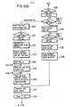
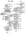
- Fig's 4 (A) and (B) are Fig's the system programs related to the preferred embodiments of the present invention.
- the main control unit 1 also incorporates RA14 20 containing buffers (IN, MA, and SA,) a counter C, a timer T, and a flag F denoting the control conditions; all of these elements are made available for implementing the system control operation.
- Buffer IN temporarily stores the phone numbers which are input through number keys on the operation panel 2, whereas buffers MA and SA temporarily store address data generated by the above address conversion table and which is present in the main dial areas.
- Flag F consists of main and subordinate flags. Timer T is activated to control the transmission of dialing signals.
- the operations of the operation panel 2 shown in Fig. 2 are described below. Note that only part of the operating panel related to the present invention is shown in Fig. 2.
- the reference numeral 32 indicates number keys needed for entering either the shortened number or entire phone number of any receiving stations. Signals generated by the number keys are converted into corresponding binary codes, which are then delivered to the main control unit 1 and shown on the display unit 30.
- a registration key 33 is a control key for input of the Shortened numbers.
- a dial key 34 controls transmission of dialing signals to receiving stations.
- a facsimile key 31 is a control key for activating the data transmission process after designation of the phone numbers of the subscriber stations.
- the reference numeral 30 indicates a liquid crystal display unit which displays either numerals that are input via the number keys 10 or messages generated by ROM 21 of the main control unit 1.
- the reference numerals 35 and 36 are lamps indicating whether the facsimile.unit is transmitting or receiving data.
- step S100 When the operator presses dial key 34 on the operation panel 2 for dialing, all the operations effective from step S100 are sequentially executed.
- the operator directly inputs the phone number of the receiving station using number keys 32, the entered number is stored in buffer IN and simultaneously appears on the display 30.
- the operator then depresses the FAX key 31.
- the dialing signal generator 9 generates a specific dial tone corresponding to the identified phone number, then it delivers the dial tone signal to the telephone circuit via the NCU 7.
- timer T is activated to allow the operation to proceed to step S130, shown in Fig. 4-(B).
- the main control unit 1 identifies in step S130 whether or not NCU 7 receives the signal from the receiving station via the exchange whether the busy signal detector 8 correctly transmits the busy signal during step S131, or whether the timer T has counted 45 seconds during step S132.
- the data reader unit 3 reads the content of the document. This data is then stored in the line memory unit 11, and finally the facsimile system transmits the stored data to the primary receiving station via the data transmission processor unit 5, the MODEM 6, and the NCU 7 during step S140.
- step S150 the operation mode then proceeds to step S150.
- steps S150 and S160 respectively indicate no answer in the operation flowchart of Fig. 4. (B), thus causing both the flag F and the counter T to be reset. This causes the system to break off its connection to the telephone circuit and then enter a dial processing operation, that is, the system repeats the operations described above after a specified period of time.
- Fig. 4 (A) When the operator presses the dial key 34 and the registration key 33, and then inputs the two-digit code dial number using number keys 32, the shortened number is stored in buffer IN and simultaneously shown on the display unit 30. Following the entry of the two-digit number, the operator depresses the FAX key 31 to activate the execution of all the operational modes effective from step S112 on.
- the binary version of the number stored in buffer IN is then converted into address data of both the main and subordinate dial areas of the dial memory 10 by means of the address conversion table of ROM 21 during step S112, and these address data are then latched by buffers MA and SA respectively during step S113.
- the main dial area 41i is accessed in accordance with the address data latched in buffer MA.
- the main control unit 1 then reads the dial number data of the preregistered receiving station for delivery to the dialing signal generator 9. This allows the system to output the signals and simultaneously activate timer T (steps S114 through S118).
- the operation modes then proceed to those steps shown in Fig. 4 (B).
- Fig. 4 (B) if no dial number data is stored in the corresponding main dial memory area, the system identifies that the operation has been incorrectly executed, and the system returns to its initial state.
- operations from S130 and SL40 are executed to allow the transmission of data to the primary receiving station.
- step S161 If the desired phone number is not yet registered, in other words, if the data are composed of binary-code (11), operational modes effective from step S161 on are executed to allow re-dialing. Conversely, if the required phone number is stored, the system turns the main flag off, the subordinate flag on and then counter C. The system then disconnects the telephone circuit. These operations are executed during steps S154 through S156, after which the operation mode proceeds to step S116 shown in Fig. 4 (A) . The main control unit 1 then delivers the phone number of the secondary receiving station retrieved from subordinate memory area 42i and sends it to the dialing signal generator 9 instructing it to transmit the dialing signal during steps S116 through S118.
- step S140 When the signal is received from the secondary receiving station, those operations effective from step S140 as shown in Fig. 4 (B) are executed for implementing the transmission of the picture data. After completing the transmission of the data, a message "All data has been transmitted to the secondary station" appears on the display unit 30. Accordingly, when the main control unit 1 identifies that the primary receiving station is busy, the main control unit 1 activates the facsimile system to immediately transmit dialing signals to a secondary station in the vicinity of the designated subscriber station, which will receive signals on its behalf. On the other hand, if the secondary receiving station is -busy, the busy signal detector 8 delivers the busy signal to the main control unit 1, thus causing a repeat of steps S131, S133, S134 and S150.
- the main control unit 1 turns timer T off as soon as the counted time exceeds 60 seconds to allow the system operation to proceed to step S115 shown in Fig. 4 (B). This also inhibits the system from transmitting dialing signals to the secondary receiving station, and as a result, the facsimile system transmits the dialing signal to the primary subscriber station again. If neither the primary nor secondary subscriber stations can transmit dialing signals, the facsimile system repeats the operations described above until transmission of dialing signals can be executed.
- Operational steps S151 and S155 cause the dialing signals to be alternately and repeatedly executed “m" times (3 times, in the example).
- the system discontinues the alternate dialing signal transmission and executes re-dialing operation.
- the dialing signal transmission process is resumed after a specified period of time. Note that, when transmitting dialing signals to a receiving station which has failed to respond, it is necessary to provide the exchange with a minimum 60 seconds stand-by time for proper connection.
- timer T which is activated in step S118, counts 45 seconds before causing the operational mode to proceed from step S132 shown in Fig. 4 (B) to step S150.
- the facsimile device embodied by the present invention activates the transmission of dialing signals to the secondary receiving station.
- the facsimile device incorporating the preferred embodiments of the present invention automatically activates the dialing signal transmission to a secondary receiving station, which receives incoming signals on behalf of the primary receiving station when it is occupied.
- the facsimile device embodied by the present invention minimizes the stand-by time until the designated dialing signal can actually be transmitted.
- the facsimile device of the present invention can potentially increase the number of secondary receiving station, which receives incoming signals on behalf of the primary receiving station when it is occupied.
Landscapes
- Engineering & Computer Science (AREA)
- Automation & Control Theory (AREA)
- Multimedia (AREA)
- Signal Processing (AREA)
- Facsimile Transmission Control (AREA)
- Facsimiles In General (AREA)
Applications Claiming Priority (4)
| Application Number | Priority Date | Filing Date | Title |
|---|---|---|---|
| JP30771/85 | 1985-02-18 | ||
| JP60030770A JPS61189771A (ja) | 1985-02-18 | 1985-02-18 | フアクシミリ装置 |
| JP30770/85 | 1985-02-18 | ||
| JP60030771A JPS61189772A (ja) | 1985-02-18 | 1985-02-18 | フアクシミリ装置 |
Publications (3)
| Publication Number | Publication Date |
|---|---|
| EP0195258A2 true EP0195258A2 (fr) | 1986-09-24 |
| EP0195258A3 EP0195258A3 (en) | 1989-02-08 |
| EP0195258B1 EP0195258B1 (fr) | 1991-09-18 |
Family
ID=26369182
Family Applications (1)
| Application Number | Title | Priority Date | Filing Date |
|---|---|---|---|
| EP86102072A Expired EP0195258B1 (fr) | 1985-02-18 | 1986-02-18 | Appareil de fac-similé |
Country Status (4)
| Country | Link |
|---|---|
| US (1) | US4741021A (fr) |
| EP (1) | EP0195258B1 (fr) |
| CA (1) | CA1245380A (fr) |
| DE (1) | DE3681474D1 (fr) |
Cited By (6)
| Publication number | Priority date | Publication date | Assignee | Title |
|---|---|---|---|---|
| EP0244869A2 (fr) * | 1986-05-08 | 1987-11-11 | Tokyo Electric Co., Ltd. | Appareil téléautographique |
| EP0265963A2 (fr) * | 1986-10-31 | 1988-05-04 | Nec Corporation | Appareil de fac-similé à sélection automatique |
| EP0360200A2 (fr) * | 1988-09-17 | 1990-03-28 | Sharp Kabushiki Kaisha | Appareil de communication utilisant une ligne téléphonique |
| US4920560A (en) * | 1987-02-18 | 1990-04-24 | Kabushiki Kaisha Toshiba | Method of automatic dialing and automatic dialing device for facsimile apparatuses |
| EP0401804A2 (fr) * | 1989-06-07 | 1990-12-12 | Sharp Kabushiki Kaisha | Dispositif de fac-similé |
| EP0481389A2 (fr) * | 1990-10-18 | 1992-04-22 | Sharp Kabushiki Kaisha | Dispositif de fac-similé |
Families Citing this family (31)
| Publication number | Priority date | Publication date | Assignee | Title |
|---|---|---|---|---|
| JPS6132652A (ja) * | 1984-07-24 | 1986-02-15 | Canon Inc | 画像通信装置 |
| JP2525369B2 (ja) * | 1986-07-23 | 1996-08-21 | キヤノン株式会社 | デ−タ通信装置 |
| JPS6339243A (ja) * | 1986-08-04 | 1988-02-19 | Canon Inc | 通信装置 |
| JP2548555B2 (ja) * | 1987-02-16 | 1996-10-30 | キヤノン株式会社 | ファクシミリ装置 |
| GB2211698B (en) * | 1987-10-23 | 1992-02-26 | American Telephone & Telegraph | Method and apparatus for transmitting documents |
| US4928302A (en) * | 1987-11-06 | 1990-05-22 | Ricoh Company, Ltd. | Voice actuated dialing apparatus |
| JPH01235447A (ja) * | 1988-03-16 | 1989-09-20 | Toshiba Corp | 有線端末装置 |
| US5014300A (en) * | 1988-08-05 | 1991-05-07 | Atlas Telecom, Inc. | Method and apparatus for accessing a facsimile store and forward network |
| US5216517A (en) * | 1988-08-24 | 1993-06-01 | Kabushiki Kaisha Toshiba | Communication terminal apparatus |
| JP2858580B2 (ja) * | 1989-04-19 | 1999-02-17 | 株式会社東芝 | ファクシミリ受信システム |
| US5216705A (en) * | 1989-07-12 | 1993-06-01 | Canon Kabushiki Kaisha | Data communication apparatus with an abbreviated dial key having a plurality of dial data and capable of selecting one of two communication functions |
| US5606716A (en) * | 1989-10-18 | 1997-02-25 | Asahi Kogaku Kogyo Kabushiki Kaisha | Device for detecting the connectivity of a monitor and inhibiting a data reproducing operation |
| JPH03265269A (ja) * | 1990-03-14 | 1991-11-26 | Fuji Xerox Co Ltd | ファクシミリ装置の回線制御方式 |
| JP2735357B2 (ja) * | 1990-04-26 | 1998-04-02 | キヤノン株式会社 | 画像通信装置 |
| JP2825972B2 (ja) * | 1990-11-29 | 1998-11-18 | 松下電器産業株式会社 | ファクシミリ装置 |
| US5199063A (en) * | 1991-02-01 | 1993-03-30 | Hewlett-Packard Company | Automatically generating telephone directory labels for facsimile devices |
| US5479500A (en) * | 1991-03-28 | 1995-12-26 | Canon Kabushiki Kaisha | Communication apparatus |
| JPH04357764A (ja) * | 1991-06-03 | 1992-12-10 | Canon Inc | 通信装置 |
| JPH0548802A (ja) * | 1991-08-21 | 1993-02-26 | Hitachi Ltd | 宛先地域オンライン表示付通信装置 |
| US5337349A (en) * | 1991-11-18 | 1994-08-09 | Matsushita Graphic Communication Systems, Inc. | Image telecommunication apparatus |
| JPH05219342A (ja) * | 1992-02-05 | 1993-08-27 | Canon Inc | ファクシミリ装置 |
| US5369686A (en) * | 1993-02-12 | 1994-11-29 | Open Port Technology, Inc. | Method and apparatus for secondary-option message delivery through enhanced service message handlers |
| JP3220632B2 (ja) * | 1995-12-20 | 2001-10-22 | シャープ株式会社 | ファクシミリ装置 |
| KR100194455B1 (ko) * | 1995-12-30 | 1999-06-15 | 윤종용 | 팩시밀리 시스템의 예약 송신방법 |
| US5905782A (en) * | 1996-05-17 | 1999-05-18 | Nko, Inc. | Facsimile jack for selectively routing transmissions through a facsimile network |
| US5828468A (en) * | 1996-05-17 | 1998-10-27 | Nko, Inc. | Point of presence (POP) for digital facsimile network with spoofing capability to maintain fax session |
| US6023470A (en) * | 1996-05-17 | 2000-02-08 | Lee; Warren S. | Point of presence (POP) for digital facsimile network with virtual POPs used to communicate with other networks |
| US5815669A (en) * | 1996-05-17 | 1998-09-29 | Nko, Inc. | Method of routing a data transmission |
| US5999274A (en) * | 1996-05-17 | 1999-12-07 | Nko, Inc. | Apparatus and method for transmitting facsimile data |
| US6075849A (en) * | 1996-05-17 | 2000-06-13 | Nko, Inc. | Method of monitoring a data transmission |
| US5739919A (en) * | 1996-05-17 | 1998-04-14 | Nko, Inc. | Point of presence (POP) for digital facsimile network |
Citations (3)
| Publication number | Priority date | Publication date | Assignee | Title |
|---|---|---|---|---|
| US3899645A (en) * | 1971-12-16 | 1975-08-12 | Yeda Res & Dev | Processor for controlling the operation of a telephone |
| US4113991A (en) * | 1977-05-03 | 1978-09-12 | Xerox Corporation | Automatic dialer having a selective retry capability |
| EP0117871A1 (fr) * | 1982-08-30 | 1984-09-12 | Fujitsu Limited | Appareil de fac-simile |
Family Cites Families (6)
| Publication number | Priority date | Publication date | Assignee | Title |
|---|---|---|---|---|
| US4160125A (en) * | 1977-05-23 | 1979-07-03 | Digital Products Corporation | Telephone polling apparatus |
| US4492820A (en) * | 1980-10-24 | 1985-01-08 | Salt Lake Communications, Inc. | Telephone alarm system |
| JPS58143671A (ja) * | 1982-02-19 | 1983-08-26 | Ricoh Co Ltd | フアクシミリシステム |
| JPS58194456A (ja) * | 1982-05-10 | 1983-11-12 | Ricoh Co Ltd | 順次同報装置 |
| JPS59185462A (ja) * | 1983-04-06 | 1984-10-22 | Ricoh Co Ltd | フアクシミリ中継方法 |
| JPS59201579A (ja) * | 1983-04-29 | 1984-11-15 | Toshiba Corp | 複合フアクシミリ装置 |
-
1986
- 1986-02-11 CA CA000501588A patent/CA1245380A/fr not_active Expired
- 1986-02-18 US US06/829,926 patent/US4741021A/en not_active Expired - Lifetime
- 1986-02-18 EP EP86102072A patent/EP0195258B1/fr not_active Expired
- 1986-02-18 DE DE8686102072T patent/DE3681474D1/de not_active Expired - Lifetime
Patent Citations (3)
| Publication number | Priority date | Publication date | Assignee | Title |
|---|---|---|---|---|
| US3899645A (en) * | 1971-12-16 | 1975-08-12 | Yeda Res & Dev | Processor for controlling the operation of a telephone |
| US4113991A (en) * | 1977-05-03 | 1978-09-12 | Xerox Corporation | Automatic dialer having a selective retry capability |
| EP0117871A1 (fr) * | 1982-08-30 | 1984-09-12 | Fujitsu Limited | Appareil de fac-simile |
Cited By (12)
| Publication number | Priority date | Publication date | Assignee | Title |
|---|---|---|---|---|
| EP0244869A2 (fr) * | 1986-05-08 | 1987-11-11 | Tokyo Electric Co., Ltd. | Appareil téléautographique |
| EP0244869A3 (en) * | 1986-05-08 | 1988-01-07 | Tokyo Electric Co., Ltd. | Facsimile apparatus |
| US4754335A (en) * | 1986-05-08 | 1988-06-28 | Tokyo Electric Co., Ltd. | Facsimile apparatus |
| EP0265963A2 (fr) * | 1986-10-31 | 1988-05-04 | Nec Corporation | Appareil de fac-similé à sélection automatique |
| EP0265963A3 (en) * | 1986-10-31 | 1989-02-15 | Nec Corporation | Auto dialling facsimile apparatus |
| US4920560A (en) * | 1987-02-18 | 1990-04-24 | Kabushiki Kaisha Toshiba | Method of automatic dialing and automatic dialing device for facsimile apparatuses |
| EP0360200A2 (fr) * | 1988-09-17 | 1990-03-28 | Sharp Kabushiki Kaisha | Appareil de communication utilisant une ligne téléphonique |
| EP0360200A3 (fr) * | 1988-09-17 | 1991-10-09 | Sharp Kabushiki Kaisha | Appareil de communication utilisant une ligne téléphonique |
| EP0401804A2 (fr) * | 1989-06-07 | 1990-12-12 | Sharp Kabushiki Kaisha | Dispositif de fac-similé |
| EP0401804A3 (fr) * | 1989-06-07 | 1992-04-22 | Sharp Kabushiki Kaisha | Dispositif de fac-similé |
| EP0481389A2 (fr) * | 1990-10-18 | 1992-04-22 | Sharp Kabushiki Kaisha | Dispositif de fac-similé |
| EP0481389A3 (en) * | 1990-10-18 | 1992-09-16 | Sharp Kabushiki Kaisha | Facsimile apparatus |
Also Published As
| Publication number | Publication date |
|---|---|
| EP0195258A3 (en) | 1989-02-08 |
| US4741021A (en) | 1988-04-26 |
| DE3681474D1 (de) | 1991-10-24 |
| EP0195258B1 (fr) | 1991-09-18 |
| CA1245380A (fr) | 1988-11-22 |
Similar Documents
| Publication | Publication Date | Title |
|---|---|---|
| EP0195258B1 (fr) | Appareil de fac-similé | |
| US5065427A (en) | Fax/data call receiving system and method | |
| EP0838962B1 (fr) | Procédé et appareil de vérification de la transmission de message | |
| US5299255A (en) | Electronic mail system for transmitting information via communication network | |
| US4764951A (en) | Auto dialer for use with telecopiers or the like | |
| CA1281444C (fr) | Appareil de telecopie | |
| US5845202A (en) | Method and apparatus for acknowledge back signaling using a radio telephone system | |
| US6002752A (en) | Method and apparatus for changing operational mode of a facsimile system | |
| JPH0522470A (ja) | データ通信装置 | |
| US5675421A (en) | Facsimile machine with a mailbox function and remote operation mode | |
| US5870206A (en) | Facsimile machine with a mailbox function | |
| JPH07336474A (ja) | ファクシミリ装置 | |
| GB2243746A (en) | Cordless telephones | |
| JPH03154559A (ja) | ファクシミリ蓄積交換装置 | |
| KR0122450B1 (ko) | 무선호출시스템에서 호처리능력 향상 방법 | |
| JP2763122B2 (ja) | ファクシミリ蓄積交換装置 | |
| JPS61189771A (ja) | フアクシミリ装置 | |
| US6452697B2 (en) | Facsimile apparatus, line control board and communication control method | |
| JP2527662B2 (ja) | ファクシミリ装置 | |
| JP2998273B2 (ja) | データ通信装置 | |
| KR100247070B1 (ko) | 팩시밀리의 음성통화 예약기능에서 전화요청메세지 전송방법 | |
| KR0136440B1 (ko) | 팩시밀리의 원격 제어 자동 송신 방법 | |
| JPH07288592A (ja) | 遠隔監視装置 | |
| JPH09163058A (ja) | データ通信装置及び方法 | |
| EP0429300A2 (fr) | Système de plusieurs terminaux répondant à un appel dans un ordre prédéterminé |
Legal Events
| Date | Code | Title | Description |
|---|---|---|---|
| PUAI | Public reference made under article 153(3) epc to a published international application that has entered the european phase |
Free format text: ORIGINAL CODE: 0009012 |
|
| 17P | Request for examination filed |
Effective date: 19860218 |
|
| AK | Designated contracting states |
Kind code of ref document: A2 Designated state(s): DE GB IT |
|
| PUAL | Search report despatched |
Free format text: ORIGINAL CODE: 0009013 |
|
| AK | Designated contracting states |
Kind code of ref document: A3 Designated state(s): DE GB IT |
|
| 17Q | First examination report despatched |
Effective date: 19901122 |
|
| GRAA | (expected) grant |
Free format text: ORIGINAL CODE: 0009210 |
|
| AK | Designated contracting states |
Kind code of ref document: B1 Designated state(s): DE GB IT |
|
| REF | Corresponds to: |
Ref document number: 3681474 Country of ref document: DE Date of ref document: 19911024 |
|
| ITF | It: translation for a ep patent filed | ||
| PLBE | No opposition filed within time limit |
Free format text: ORIGINAL CODE: 0009261 |
|
| STAA | Information on the status of an ep patent application or granted ep patent |
Free format text: STATUS: NO OPPOSITION FILED WITHIN TIME LIMIT |
|
| 26N | No opposition filed | ||
| REG | Reference to a national code |
Ref country code: GB Ref legal event code: IF02 |
|
| PGFP | Annual fee paid to national office [announced via postgrant information from national office to epo] |
Ref country code: DE Payment date: 20050210 Year of fee payment: 20 |
|
| PGFP | Annual fee paid to national office [announced via postgrant information from national office to epo] |
Ref country code: GB Payment date: 20050216 Year of fee payment: 20 |
|
| PGFP | Annual fee paid to national office [announced via postgrant information from national office to epo] |
Ref country code: IT Payment date: 20050225 Year of fee payment: 20 |
|
| REG | Reference to a national code |
Ref country code: GB Ref legal event code: PE20 |
|
| PG25 | Lapsed in a contracting state [announced via postgrant information from national office to epo] |
Ref country code: GB Free format text: LAPSE BECAUSE OF EXPIRATION OF PROTECTION Effective date: 20060217 |