EP0195157B1 - Verfahren zur Formung von Rahmenteilen mit Kastenquerschnitt - Google Patents
Verfahren zur Formung von Rahmenteilen mit Kastenquerschnitt Download PDFInfo
- Publication number
- EP0195157B1 EP0195157B1 EP85306675A EP85306675A EP0195157B1 EP 0195157 B1 EP0195157 B1 EP 0195157B1 EP 85306675 A EP85306675 A EP 85306675A EP 85306675 A EP85306675 A EP 85306675A EP 0195157 B1 EP0195157 B1 EP 0195157B1
- Authority
- EP
- European Patent Office
- Prior art keywords
- blank
- die
- deformed
- section
- cross
- Prior art date
- Legal status (The legal status is an assumption and is not a legal conclusion. Google has not performed a legal analysis and makes no representation as to the accuracy of the status listed.)
- Expired
Links
Images
Classifications
-
- B—PERFORMING OPERATIONS; TRANSPORTING
- B21—MECHANICAL METAL-WORKING WITHOUT ESSENTIALLY REMOVING MATERIAL; PUNCHING METAL
- B21D—WORKING OR PROCESSING OF SHEET METAL OR METAL TUBES, RODS OR PROFILES WITHOUT ESSENTIALLY REMOVING MATERIAL; PUNCHING METAL
- B21D51/00—Making hollow objects
-
- B—PERFORMING OPERATIONS; TRANSPORTING
- B21—MECHANICAL METAL-WORKING WITHOUT ESSENTIALLY REMOVING MATERIAL; PUNCHING METAL
- B21D—WORKING OR PROCESSING OF SHEET METAL OR METAL TUBES, RODS OR PROFILES WITHOUT ESSENTIALLY REMOVING MATERIAL; PUNCHING METAL
- B21D26/00—Shaping without cutting otherwise than using rigid devices or tools or yieldable or resilient pads, i.e. applying fluid pressure or magnetic forces
- B21D26/02—Shaping without cutting otherwise than using rigid devices or tools or yieldable or resilient pads, i.e. applying fluid pressure or magnetic forces by applying fluid pressure
- B21D26/033—Deforming tubular bodies
-
- B—PERFORMING OPERATIONS; TRANSPORTING
- B62—LAND VEHICLES FOR TRAVELLING OTHERWISE THAN ON RAILS
- B62D—MOTOR VEHICLES; TRAILERS
- B62D25/00—Superstructure or monocoque structure sub-units; Parts or details thereof not otherwise provided for
-
- Y—GENERAL TAGGING OF NEW TECHNOLOGICAL DEVELOPMENTS; GENERAL TAGGING OF CROSS-SECTIONAL TECHNOLOGIES SPANNING OVER SEVERAL SECTIONS OF THE IPC; TECHNICAL SUBJECTS COVERED BY FORMER USPC CROSS-REFERENCE ART COLLECTIONS [XRACs] AND DIGESTS
- Y10—TECHNICAL SUBJECTS COVERED BY FORMER USPC
- Y10T—TECHNICAL SUBJECTS COVERED BY FORMER US CLASSIFICATION
- Y10T29/00—Metal working
- Y10T29/49—Method of mechanical manufacture
- Y10T29/49805—Shaping by direct application of fluent pressure
Definitions
- the present invention relates to a method of forming box-like frame members.
- frame members In the construction of, for example, automobiles and other road vehicles, hollow box-like frame members are frequently required. These frame members usually have one or more pairs of generally flat and opposing side faces.
- the hollow section imparts lightness in weight while providing good rigidity and other desirable mechanical characteristics.
- the flat surfaces are convenient for making connections to the frame member, for example by welding, or otherwise fastening thereto, connection elements such as stubs, lugs, brackets and flanges.
- such frame members are made by stamping out channel-shaped half shells from sheet metal.
- the half shells are welded together along edge flanges thereof to provide a box-like configuration.
- This procedure is relatively time- consuming and expensive since it requires the use of complex progressive dies for stamping out the half shells and requires complex weldin equipment, at least where the welding operation is to be performed automatically. Further, the stamping operation produces large amounts of scrap sheet metal.
- the extensive welding that is required tends to result in the product having imperfections, because of the difficulties of control that are inherent in welding operations.
- the welded areas need to be ground down to some extent, and this is time and energy consuming..
- the present invention provides in a preferred embodiment a method of forming box-like frame members by expanding a tubular blank circumferentially by application of internal fluid pressure while the blank is confined within a die cavity.
- This method is much simpler and requires much less complex equipment than the known procedure of welding stamped parts. While procedures for expansion of tubular blanks are known, the prior proposals of which the applicant is aware have been incapable of producing expanded blanks having the strength properties and dimensional uniformity or repeatability and accuracy required for box-like constructional frame members.
- a tubular blank of smoothly continuous arcuate profile preferably circular, has its side walls deformed inwardly, to provide a deformed elongate portion of uniform cross-section, at least along the portion or portions of the blank generally corresponding in position to the generally opposed planar faces desired in the product frame member, to provide the blank with concavely curved side wall portions.
- This permits the blank to be expanded to the desired generally .flat-faced cross-section without excessively large circumferential expansion of the blank.
- the inward deformation of the side walls diminishes the general cross-sectional outline, or envelope, of the blank, it permits it to be confined between a sectional forming die without the sections of the die pinching the blank on closing of the die.
- the tube blank is expanded so that all its outer surfaces conform to the inside of the die cavity, thus reproducing the dimensions of the interior surfaces of the die cacity with a high degree of accuracy and uniformity.
- the present method of forming a box-section frame member of which at least an elongate portion is of a uniform cross-section having at least two opposed and planar side faces is characterized by providing a tubular blank having a continuous, smooth, arcuate cross-section; deforming the side walls of the blank inwardly in opposed areas of at least one elongate portion thereof corresponding in position to the planar side faces desired in the final frame member and thereby providing the blank with a continuous, smooth, arcuate cross-section including opposed inwardly recessed concavely curved side-wall portions; enclosing the deformed tubular blank within a sectional die having at least two cooperating die sections defining an elongate cavity of approximately the shape of the deformed blank and which is throughout of smooth, continuous, cross-sectional profile and is in all transverse dimensions larger than the deformed blank and has an elongate planar side face opposing each concavely curved side wall portion of the blank; expanding the blank circumferentially by application of internal fluid pressure until
- the present method can produce frame members with excellent strength characteristics, and with excellent dimensional accuracy and uniformity.
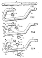
- Figure 1 shows a tubular metal blank 10 which forms the starting material for the method of the invention.
- Figure 4 shows the product or frame member 11 which it is desired to form.
- the configuration of the product 11, and the positioning of the flat side surfaces thereon is dictated by the intended end use of the frame member.
- the shape of the product 11 should be selected so it has substantially the same circumference at all transverse cross-sectional profiles, so that the wall of the blank 10 is not excessively thinned and weakened at any point, and thus avoiding introducing into the finished product any point of mechanical weakness.
- the largest circumference of any cross-sectional profile of the finished frame member will be no more than about 20% larger than the smallest circumference, and, more preferably, is no more than about 5% larger.
- the circumference of the product frame member 11 is at no point more than about 5% larger than the circumference of the blank 10. Applicant has found that, at least with the readily available grades of tubular steel, if the blank is expanded in circumference by more than about 5%, there is a tendency for the material of the wall of the blank to excessively weaken to crack, or to yield. While expansions of the tube circumference of up to about 20% can be performed if the metal of the tube is fully annealed, it is preferred to conduct the method without employing special pretreatments of the material of the blank, such as annealing.
- the product frame member 11 has, at all cross-sections, a profile with a circumference which is uniform, and is in the range about 2 to about 4% larger than the circumference of the blank 10.
- the desired product frame which, in the example shown is a car sub-frame, is symmetrical about a transverse median plane, and has a linear intermediate section 12, connected at each end through a curved transition or elbow 13 to an end portion 14, which inclines at an oblique angle to the intermediate portion 12.
- Each end portion 14 extends at the same angle of, e.g. about 135°, outwardly from the axis of the intermediate portion 12, and thus the portions 12 and 14 define a first plane.
- Each end portion 14 is connected through a further curved transition or elbow 16 to an outer end portion 17.
- Each outer end portion 17 extends in the same plane at an angle to the plane defined by the portions 12 and 14.
- Each outer end portion 17 may extend generally parallel to the transverse median plane of the sub-frame, or at a slight angle outwardly with respect thereto.
- the desired sub-frame has varying non-circular cross-sectional profiles.
- the applicant has found that, in order to avoid structural weaknesses in the product, it is desirable to select the design of the product so that at all transverse cross-sections, the profile is smoothly continuous, and does not include sharp angularities or discontinuities which can give rise to concentrations of stress and can lead to structural weaknesses.
- the intermediate section 12 of the frame has a generally trapezoidal profile 18, with inclining sides 19 and 21, and approximately parallel sides 22 and 23. The sides are joined through gently rounded corner portions, and each of the sides 19 through 23 may themselves be gently convexly curved.
- Each end portion 14 is of an approximately square cross-section 24 with upper and lower sides 26 and 27 and lateral sides 28 and 29.
- the outer end portions 17 are each of a generally rectangular configuration 31, with upper and lower sides 32 and 33, and lateral sides 34 and 36.
- the profiles 24 and 31 are wholly smoothly continuous, with rounded corner sections joining the approximately linear sides 26 through 29 and 32 through 36. These sides may be gently outwardly convexly curved.
- the transition section 13 between the generally trapezoidal intermediate section 12 and each end portion 14 blends smoothly at each end with the sections 12 and 14, respectively, and, in its midpoint, is approximately circular.
- the transition section 16 between each end portion 14 and each outer end portion 17 is generally rectangular, and, again, blends smoothly at each end with the sections 14 and 17.
- transition section 16 tends to taper in height, as the upper and lower side walls 26 and 27 merge toward the reduced height upper and lower side walls 32 and 33 of the outer end portions 17, while the sides of the transition section 16 tend to flare outwardly from the end portion 14 toward the outer end portion 17.
- the blank 10 is first bent into approximately the configuration of the desired product frame member, to provide it with an intermediate section 12a, outwardly bent end portions 14a, and outer end portions 17a. As shown, the blank 10 is bent so that, throughout its length, it preserves the circular cross-section 18a, as indicated in Figure 2, and without the blank 10 substantially changing its circumference at any cross-section thereof.
- the bending operation may be performed using conventional bending procedures, for example using internal mandrels and external bending tools, i.e. mandrel bending, or by stretch bending, which employs no internal mandrel. These bending procedures are generally well known among those skilled in the art, and need not be described in detail herein.
- the minimum radius of bend that may be imparted to the tube is approximately twice the diameter of the tube blank 10, and the minimum distance between adjacent bent portions is approximately one tube diameter.
- a cross-sectional area reduction of about 5% is usually achieved.
- stretch bending employing no mandrel
- the minimum bend radius will be approximately 3 times the diameter of the blank 10
- the minimum distance between adjacent bends will be approximately one-half of the diameter of the blank 10.
- a cross-sectional area reduction of about 15% is achieved.
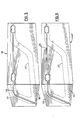
- the inwardly bent profiles for example the profiles 18b, 24b and 31 b are selected so that, at all cross-sections, the blank preserves a smoothly continuous and gently rounded cross-sectional profile. It has been found that this avoids creation of points of stress in the blank during the inward deformation procedure and in the subsequent expansion step, and is thus conducive to forming a product with excellent mechanical strength.
- the intermediate section 12b of the bent blank is formed to a uniform cross-section as indicated at 18b in Figure 3.
- This has a concavely curved profile 19b and 21 b in the regions thereof which correspond to the inclining sides 19 and 21 of the product frame member.
- each end section 14b is formed to a uniform cross-section 24b, which has concavely recessed upper and lower sides 26b and 27b in the regions corresponding to the upper and lower approximately linear profile sides 26 and 27 in the product.
- the outer end portion 17b of the bent blank is deformed to the profile indicated at 31 b in Figure 3, having upper and lower inwardly arcuately curved sides 32b and 33b.
- transition sections or elbows 13b and 16b, between the intermediate section 12b and the end sections 14b, and between the section 14b and the outer end portion 17b, respectively, have cross-sectional profiles which vary along their length, and merge smoothly at each end with the adjacent non-circular section profiles 18b, 14b and 17b.
- the central portion of the transition portion 13b will be of circular cross-section, while the transition section 16b becomes progressively more elongate laterally, and shallower as it extends from the end portion 14b toward the outer end portion 17b.
- the inward deformation of the side walls of the bent blank, to provide it with the varying cross-sections illustrated in Figure 3, can be conducted using conventional and generally well known metal forming techniques.
- the operation is conducted by pressing the generally circular section bent blank as shown in Figure 2 in a two-part sectional die 36, as illustrated in Figure 5, having upper and lower die halves 37 and 38, respectively, which has a non-planar separation zone 39 conforming to the non-planar configuration of the bent tubular blank as shown in Figure 2.
- the die halves are formed along this separation zone with die cavities which, when the halves are brought into opposition, cooperate to form a die cavity having the profile of the deformed blank shown in Figure 3.
- the circular-section tubular blank as shown in Figure 2 is placed in the cavity of the lower die half 38, and the upper half 37 of the die is brought downwardly toward the lower half 38 until the two portions contact each other and form the shape as shown in Figure 3.
- a two-part sectional die 42 is employed as shown in Figure 6. This has upper and lower die halves 43 and 44, which have between them a non-planar separation zone 46. On the sides of the die halves 43 and 44 adjacent the zone 46, the die halves 43 and 44 are formed with cavity portions which, when the portions 43 and 44 are brought together, define a cavity 47 conforming to the desired product shown in Figure 4.
- the final product as shown in Figure 4 is selected so that, at all cross-sections, its circumference is substantially the same, and is in the range about 2 to about 4% larger than the circumference of the starting material tubular blank 10. It will therefore be appreciated, that the intermediate blank shown in Figure 3 will fit within an envelope which is smaller than that of the final product shown in Figure 4.
- the deformed intermediate tube blank shown in Figure 3 can therefore be placed loosely within the cavity portion of the lower half 44 of the final form die, and the upper die section 43 can be placed on top of the lower section 44 to enclose the intermediate blank without pinching the intermediate blank or otherwise deforming it.
- the upper and lower die sections 43 and 44 are held together with sufficient force to prevent any movement during the procedure of expansion of the intermediate blank to the final form.
- Conventional procedures may be employed to apply internal pressure to the intermediate blank to expand it - circumferentially to the final form. Briefly, both ends of the intermediate tubular blank may be sealed, and, through one of these seals, hydraulic fluid is injected at sufficient pressure to expand the blank until all its external surfaces conform to the inner side of the die cavity 47. This procedure produces the varying geometrical cross-sections illustrated to a very high degree of accuracy, uniformity and repeatability.
- the pressure is released, the hydraulic fluid is pumped out of the interior of the deformed tube, and the upper and lower die sections 43 and 44 are separated and the final product is removed from the die.
- any material having sufficient ductility to be processed by the method described above can be employed.
- materials such as mild steel can be employed without any special pretreatment such as annealing.
- an 89 mm (3-1/2 inch) diameter by 2 mm (0.080 inch) wall thickness by 1524 mm (60 inch) long tube of SAE 1010 steel was employed, and was formed and expanded to a product having the configuration shown in Figure 4, the degree of circumferential expansion being about 3% at all cross-sections of the tube.
- a starting material blank 10 of a smoothly-rounded non-circular cross-section for example of eliptical cross-section, may be employed.
- each die cavity in the die 42 (and preferably also in the pre-forming die 36) has its side surfaces disposed at slight draft angles. This avoids any tendency of the intermediate blank or final product to engage within the die cavity, and permits the intermediate blank or final product to be readily removed from the die.
- lubricants do not need to be applied to the surfaces of the intermediate blank or to the surfaces of the dies 36 and 42.
Claims (10)
Priority Applications (1)
| Application Number | Priority Date | Filing Date | Title |
|---|---|---|---|
| AT85306675T ATE48772T1 (de) | 1985-03-19 | 1985-09-19 | Verfahren zur formung von rahmenteilen mit kastenquerschnitt. |
Applications Claiming Priority (2)
| Application Number | Priority Date | Filing Date | Title |
|---|---|---|---|
| US713750 | 1985-03-19 | ||
| US06/713,750 US4567743A (en) | 1985-03-19 | 1985-03-19 | Method of forming box-section frame members |
Publications (3)
| Publication Number | Publication Date |
|---|---|
| EP0195157A2 EP0195157A2 (de) | 1986-09-24 |
| EP0195157A3 EP0195157A3 (en) | 1987-05-06 |
| EP0195157B1 true EP0195157B1 (de) | 1989-12-20 |
Family
ID=24867376
Family Applications (1)
| Application Number | Title | Priority Date | Filing Date |
|---|---|---|---|
| EP85306675A Expired EP0195157B1 (de) | 1985-03-19 | 1985-09-19 | Verfahren zur Formung von Rahmenteilen mit Kastenquerschnitt |
Country Status (9)
| Country | Link |
|---|---|
| US (1) | US4567743A (de) |
| EP (1) | EP0195157B1 (de) |
| JP (1) | JPS61219435A (de) |
| KR (1) | KR890003280B1 (de) |
| AT (1) | ATE48772T1 (de) |
| BR (1) | BR8504492A (de) |
| CA (1) | CA1227921A (de) |
| DE (1) | DE3574834D1 (de) |
| MX (1) | MX162457A (de) |
Cited By (6)
| Publication number | Priority date | Publication date | Assignee | Title |
|---|---|---|---|---|
| DE4142325A1 (de) * | 1991-12-20 | 1993-06-24 | Bayerische Motoren Werke Ag | Verfahren zum herstellen von fahrwerkstraegern |
| DE4214557A1 (de) * | 1992-04-28 | 1993-11-04 | Mannesmann Ag | Verfahren zum hydraulischen aufweiten von geschlossenen hohlprofilen |
| DE19708905A1 (de) * | 1997-03-05 | 1998-04-16 | Daimler Benz Ag | Verfahren zum Herstellen von Karosserieträgern |
| DE19706218A1 (de) * | 1997-02-18 | 1998-08-20 | Siempelkamp Pressen Sys Gmbh | Verfahren zum Formen eines gebogenen Bauteils im Rahmen der Innenhochdruck-Umformtechnik und Vorrichtung für die Durchführung des Verfahrens |
| DE102008014213A1 (de) | 2008-03-13 | 2009-09-17 | Schuler Hydroforming Gmbh & Co. Kg | Verfahren zum Herstellen von Werkstücken aus einem rohrförmigen Hohlprofilrohling durch Beaufschlagung mit einem hohen Innendruck |
| DE102013212758A1 (de) | 2013-06-28 | 2014-12-31 | Bayerische Motoren Werke Aktiengesellschaft | Werkzeug zum Vorformen eines Rohrs für ein anschließendes Innenhochdruckumformen, sowie Verfahren zur Herstellung eines solchen Werkzeugs und zur Herstellung eines Bauteils durch Innenhochdruckumformen |
Families Citing this family (56)
| Publication number | Priority date | Publication date | Assignee | Title |
|---|---|---|---|---|
| US4744237A (en) * | 1987-05-06 | 1988-05-17 | Ti Automotive Division Of Ti Canada Inc. | Method of forming box-like frame members |
| US4829803A (en) * | 1987-05-06 | 1989-05-16 | Ti Corporate Services Limited | Method of forming box-like frame members |
| USRE33990E (en) * | 1987-05-06 | 1992-07-14 | Ti Corporate Services Limited | Method of forming box-like frame members |
| US4776196A (en) * | 1987-07-14 | 1988-10-11 | Ti Automotive Division Of Ti Canada Inc. | Process and apparatus for forming flanged ends on tubular workpieces |
| US4759111A (en) * | 1987-08-27 | 1988-07-26 | Ti Automotive Division Of Ti Canada Inc. | Method of forming reinforced box-selection frame members |
| CA2023675C (en) * | 1989-08-24 | 2001-07-31 | Ralph E. Roper | Apparatus and method for forming a tubular frame member |
| US5890387A (en) * | 1989-08-24 | 1999-04-06 | Aquaform Inc. | Apparatus and method for forming and hydropiercing a tubular frame member |
| US5353618A (en) * | 1989-08-24 | 1994-10-11 | Armco Steel Company, L.P. | Apparatus and method for forming a tubular frame member |
| US5481892A (en) * | 1989-08-24 | 1996-01-09 | Roper; Ralph E. | Apparatus and method for forming a tubular member |
| DE4017072A1 (de) * | 1990-05-26 | 1991-11-28 | Benteler Werke Ag | Verfahren zum hydraulischen umformen eines rohrfoermigen hohlkoerpers und vorrichtung zur durchfuehrung des verfahrens |
| US5070717A (en) * | 1991-01-22 | 1991-12-10 | General Motors Corporation | Method of forming a tubular member with flange |
| US5170557A (en) * | 1991-05-01 | 1992-12-15 | Benteler Industries, Inc. | Method of forming a double wall, air gap exhaust duct component |
| AU752981B2 (en) * | 1992-09-15 | 2002-10-03 | Aquaform, Inc | Apparatus and method for forming and hydropiercing a tubular frame member |
| US5327764A (en) * | 1993-04-05 | 1994-07-12 | Aluminum Company Of America | Apparatus and method for the stretch forming of elongated hollow metal sections |
| US5349839A (en) * | 1993-04-05 | 1994-09-27 | Aluminum Company Of America | Flexible constraining apparatus and method for the stretch forming of elongated hollow metal sections |
| US5339667A (en) * | 1993-04-19 | 1994-08-23 | General Motors Corporation | Method for pinch free tube forming |
| EP0621091B1 (de) * | 1993-04-19 | 1997-06-11 | General Motors Corporation | Verfahren zum Formen eines rohrförmigen Elementes |
| US5363544A (en) * | 1993-05-20 | 1994-11-15 | Benteler Industries, Inc. | Multi-stage dual wall hydroforming |
| US5644829A (en) * | 1993-08-16 | 1997-07-08 | T I Corporate Services Limited | Method for expansion forming of tubing |
| US5471857A (en) * | 1994-03-07 | 1995-12-05 | Mascotech Tubular Products, Inc. | Process for hydroforming a vehicle manifold |
| DE4412108C1 (de) * | 1994-04-08 | 1995-11-02 | Porsche Ag | Überrollbügel für ein Kraftfahrzeug |
| US5561902A (en) * | 1994-09-28 | 1996-10-08 | Cosma International Inc. | Method of manufacturing a ladder frame assembly for a motor vehicle |
| US5666727A (en) * | 1995-02-17 | 1997-09-16 | General Motors Corporation | Method of manufacturing a passenger compartment from a cylindrical tube |
| EP0760265A1 (de) * | 1995-08-26 | 1997-03-05 | Benteler Ag | Rohr zur Verwendung bei der Herstellung von Kraftfahrzeugkomponenten und Kraftfahrzeugachse mit einem solchen Rohr |
| US5884722A (en) * | 1997-01-23 | 1999-03-23 | Dana Corporation | Engine cradle for vehicle body and frame assembly and method of manufacturing same |
| US5882039A (en) * | 1997-01-23 | 1999-03-16 | Dana Corporation | Hydroformed engine cradle and cross member for vehicle body and frame assembly |
| AU2170297A (en) * | 1997-03-27 | 1998-10-22 | Ti Corporate Services Limited | Method and apparatus for forming of tubing |
| US5992197A (en) * | 1997-03-28 | 1999-11-30 | The Budd Company | Forming technique using discrete heating zones |
| DE19882390B4 (de) * | 1997-05-12 | 2010-02-18 | Dana Automotive Systems Group, LLC, Toledo | Hydroformverfahren |
| US6006567A (en) * | 1997-05-15 | 1999-12-28 | Aquaform Inc | Apparatus and method for hydroforming |
| US6502822B1 (en) | 1997-05-15 | 2003-01-07 | Aquaform, Inc. | Apparatus and method for creating a seal on an inner wall of a tube for hydroforming |
| US6120059A (en) * | 1997-06-04 | 2000-09-19 | Dana Corporation | Vehicle frame assembly |
| GB9721465D0 (en) * | 1997-10-10 | 1997-12-10 | Gkn Sankey Ltd | A process for producing a tubular structural element |
| US6070445A (en) * | 1997-10-29 | 2000-06-06 | Trw Inc. | Method of manufacturing the control arm |
| US6006568A (en) * | 1998-03-20 | 1999-12-28 | The Budd Company | Multi-piece hydroforming tool |
| US6098437A (en) * | 1998-03-20 | 2000-08-08 | The Budd Company | Hydroformed control arm |
| DE19813012C2 (de) * | 1998-03-25 | 2002-08-01 | Daimler Chrysler Ag | Verfahren zum Herstellen eines Hohlkörpers aus einem rohrförmigen Rohling durch Innenhochdruckformung |
| US6216509B1 (en) | 1998-08-25 | 2001-04-17 | R.J. Tower Corporation | Hydroformed tubular member and method of hydroforming tubular members |
| JP3688921B2 (ja) * | 1999-01-14 | 2005-08-31 | 日産自動車株式会社 | 液圧成形ノズルおよび液圧成形装置 |
| US6032501A (en) * | 1999-02-09 | 2000-03-07 | The Budd Company | Method of hydroforming multi-lateral members from round tubes |
| US6279364B1 (en) * | 1999-02-16 | 2001-08-28 | Gary E. Morphy | Sealing method and press apparatus |
| US6609301B1 (en) | 1999-09-08 | 2003-08-26 | Magna International Inc. | Reinforced hydroformed members and methods of making the same |
| WO2001060544A2 (en) * | 2000-02-18 | 2001-08-23 | Cosma International Inc. | Tubular assembly having hydroformed interconnecting member and method for making same |
| US6662611B2 (en) | 2000-02-22 | 2003-12-16 | Magna International, Inc. | Hydroforming flush system |
| IT1320503B1 (it) * | 2000-06-16 | 2003-12-10 | Iveco Fiat | Procedimento per la produzione di assali per veicoli industriali. |
| SE0003655D0 (sv) * | 2000-10-10 | 2000-10-10 | Avesta Sheffield Ab | Förfarande och anordning för tillverkning av ett ien rörkonstruktion ingående rör samt ett rör tillverkat enligt förfarandet |
| JP3834276B2 (ja) * | 2002-08-30 | 2006-10-18 | 伊田 忠一 | 中空パイプの冷間折曲加工法 |
| US6764559B2 (en) | 2002-11-15 | 2004-07-20 | Commonwealth Industries, Inc. | Aluminum automotive frame members |
| US20040250404A1 (en) * | 2003-01-14 | 2004-12-16 | Cripsey Timothy J. | Process for press forming metal tubes |
| US20060096099A1 (en) * | 2003-05-08 | 2006-05-11 | Noble Metal Processing, Inc. | Automotive crush tip and method of manufacturing |
| DE10351137B3 (de) * | 2003-11-03 | 2005-02-24 | Daimlerchrysler Ag | Verfahren zur Herstellung eines Fahrzeugbauteils, insbesondere eines Fahrwerkrahmens |
| FR2874174B1 (fr) * | 2004-08-11 | 2006-11-24 | Bourjois Soc Par Actions Simpl | Composition cosmetique comprenant un polymere superabsorbant |
| JP5299936B2 (ja) * | 2005-08-08 | 2013-09-25 | 日産自動車株式会社 | 中空状成形体の成形方法および成形装置並びに中空状成形体 |
| KR100851828B1 (ko) * | 2006-11-08 | 2008-08-13 | 현대자동차주식회사 | U자형 제품 제작을 위한 하이드로 포밍 장치 |
| JP5339774B2 (ja) * | 2008-05-20 | 2013-11-13 | 日本発條株式会社 | 車両用シートバックのフレーム構造及び該構造を有する車両用シートバック |
| DE102018115052A1 (de) | 2018-06-22 | 2019-12-24 | Salzgitter Hydroforming GmbH & Co. KG | Verfahren zur Herstellung eines gebogenen, rohrförmigen Vorproduktes aus Metall für die Innenhochdruckumformung von Bauteilen und Werkzeug zur Herstellung eines solchen Vorproduktes |
Family Cites Families (9)
| Publication number | Priority date | Publication date | Assignee | Title |
|---|---|---|---|---|
| US1210629A (en) * | 1914-04-16 | 1917-01-02 | Charles G Conn | Process of calibrating and justifying parts of wind musical instruments. |
| US3768288A (en) * | 1971-02-25 | 1973-10-30 | Jury & Spiers Pty Ltd | Process for the production of tube from ductile metal |
| JPS5396963A (en) * | 1977-02-04 | 1978-08-24 | Yamaha Motor Co Ltd | Manufacturing method of fuel tank for autoobicycle |
| JPS5410268A (en) * | 1977-06-24 | 1979-01-25 | Nippon Musical Instruments Mfg | Method of making cylindrical member |
| US4125937A (en) * | 1977-06-28 | 1978-11-21 | Westinghouse Electric Corp. | Apparatus for hydraulically expanding a tube |
| US4238878A (en) * | 1979-03-09 | 1980-12-16 | Brooks & Perkins, Incorporated | Method and apparatus for forming shroud |
| JPS6016855B2 (ja) * | 1979-09-27 | 1985-04-27 | 勲 木村 | 自転車用一体型前ホ−ク材の油圧バルジ成形法 |
| JPS56154228A (en) * | 1980-04-28 | 1981-11-28 | Yamamoto Suiatsu Kogyosho:Kk | Hydraulic bulging method |
| JPS59130633A (ja) * | 1983-01-17 | 1984-07-27 | Masanobu Nakamura | 小曲率曲管の製造方法 |
-
1985
- 1985-03-19 US US06/713,750 patent/US4567743A/en not_active Expired - Lifetime
- 1985-04-16 CA CA000479290A patent/CA1227921A/en not_active Expired
- 1985-09-16 BR BR8504492A patent/BR8504492A/pt not_active IP Right Cessation
- 1985-09-19 EP EP85306675A patent/EP0195157B1/de not_active Expired
- 1985-09-19 DE DE8585306675T patent/DE3574834D1/de not_active Expired - Lifetime
- 1985-09-19 AT AT85306675T patent/ATE48772T1/de not_active IP Right Cessation
- 1985-11-08 JP JP60250560A patent/JPS61219435A/ja active Granted
- 1985-11-15 MX MX628A patent/MX162457A/es unknown
-
1986
- 1986-03-19 KR KR1019860002018A patent/KR890003280B1/ko not_active IP Right Cessation
Cited By (8)
| Publication number | Priority date | Publication date | Assignee | Title |
|---|---|---|---|---|
| DE4142325A1 (de) * | 1991-12-20 | 1993-06-24 | Bayerische Motoren Werke Ag | Verfahren zum herstellen von fahrwerkstraegern |
| DE4214557A1 (de) * | 1992-04-28 | 1993-11-04 | Mannesmann Ag | Verfahren zum hydraulischen aufweiten von geschlossenen hohlprofilen |
| DE19706218A1 (de) * | 1997-02-18 | 1998-08-20 | Siempelkamp Pressen Sys Gmbh | Verfahren zum Formen eines gebogenen Bauteils im Rahmen der Innenhochdruck-Umformtechnik und Vorrichtung für die Durchführung des Verfahrens |
| DE19706218C2 (de) * | 1997-02-18 | 1999-05-06 | Siempelkamp Pressen Sys Gmbh | Verfahren zum Formen eines gebogenen Bauteils im Rahmen der Innenhochdruck-Umformtechnik und Vorrichtung für die Durchführung des Verfahrens |
| DE19708905A1 (de) * | 1997-03-05 | 1998-04-16 | Daimler Benz Ag | Verfahren zum Herstellen von Karosserieträgern |
| DE19708905C2 (de) * | 1997-03-05 | 2002-06-27 | Daimler Chrysler Ag | Verfahren zum Herstellen von Karosserieträgern |
| DE102008014213A1 (de) | 2008-03-13 | 2009-09-17 | Schuler Hydroforming Gmbh & Co. Kg | Verfahren zum Herstellen von Werkstücken aus einem rohrförmigen Hohlprofilrohling durch Beaufschlagung mit einem hohen Innendruck |
| DE102013212758A1 (de) | 2013-06-28 | 2014-12-31 | Bayerische Motoren Werke Aktiengesellschaft | Werkzeug zum Vorformen eines Rohrs für ein anschließendes Innenhochdruckumformen, sowie Verfahren zur Herstellung eines solchen Werkzeugs und zur Herstellung eines Bauteils durch Innenhochdruckumformen |
Also Published As
| Publication number | Publication date |
|---|---|
| JPS61219435A (ja) | 1986-09-29 |
| US4567743A (en) | 1986-02-04 |
| EP0195157A3 (en) | 1987-05-06 |
| KR890003280B1 (ko) | 1989-09-06 |
| MX162457A (es) | 1991-05-13 |
| ATE48772T1 (de) | 1990-01-15 |
| DE3574834D1 (de) | 1990-01-25 |
| CA1227921A (en) | 1987-10-13 |
| KR860007040A (ko) | 1986-10-06 |
| JPH0555209B2 (de) | 1993-08-16 |
| EP0195157A2 (de) | 1986-09-24 |
| BR8504492A (pt) | 1986-12-16 |
Similar Documents
| Publication | Publication Date | Title |
|---|---|---|
| EP0195157B1 (de) | Verfahren zur Formung von Rahmenteilen mit Kastenquerschnitt | |
| KR970010546B1 (ko) | 보강시킨 박스단면형 프레임 부재의 성형방법 | |
| CA1309239C (en) | Method of forming box-like frame members | |
| US4829803A (en) | Method of forming box-like frame members | |
| JP4713471B2 (ja) | 縦方向にスロットを有し、そして、異なる断面を有するいくつかの縦方向セグメントを備えている中空形材を、金属シートから製造する方法 | |
| JP2002523239A (ja) | チューブ状部材の製造方法 | |
| US8141404B2 (en) | Method of manufacturing structural components from tube blanks of variable wall thickness | |
| US4185370A (en) | Method of making a wheel rim | |
| USRE33990E (en) | Method of forming box-like frame members | |
| US6763693B1 (en) | Method for shaping an initial profile or a similar workpiece using an internal high pressure and profile therefor | |
| US6209372B1 (en) | Internal hydroformed reinforcements | |
| JPWO2004041458A1 (ja) | 液圧バルジ加工用異形素管、並びにこれを用いる液圧バルジ加工装置、液圧バルジ加工方法、および液圧バルジ加工品 | |
| US20050160783A1 (en) | Method of making pre-formed tubular members | |
| CN115066301A (zh) | 中空部件的制造方法 | |
| EP1838472B1 (de) | Verfahren zur formung des offenen endes eines rohrförmigen körpers | |
| KR20060034639A (ko) | 금속 튜브 프레스 성형 방법 | |
| JPH08174047A (ja) | 中空押出形材を用いた自動車用構造部材の成形方法 | |
| SU1754289A1 (ru) | Способ получени полых изделий из трубчатых заготовок | |
| SU902909A1 (ru) | Способ производства замкнутых профилей | |
| SU1666254A1 (ru) | Способ изготовлени ободьев дл колес | |
| RU1794539C (ru) | Способ изготовлени деталей с фланцем криволинейной формы в плане с вогнутым участком | |
| CA1153041A (en) | Method of making a wheel rim | |
| JPH01105088A (ja) | 接続用フランジ付金属管およびその製造方法 | |
| JPH0547303B2 (de) | ||
| JP2002192253A (ja) | 突起付き中空軸とその製造方法 |
Legal Events
| Date | Code | Title | Description |
|---|---|---|---|
| PUAI | Public reference made under article 153(3) epc to a published international application that has entered the european phase |
Free format text: ORIGINAL CODE: 0009012 |
|
| AK | Designated contracting states |
Kind code of ref document: A2 Designated state(s): AT BE CH DE FR GB IT LI LU NL SE |
|
| PUAL | Search report despatched |
Free format text: ORIGINAL CODE: 0009013 |
|
| AK | Designated contracting states |
Kind code of ref document: A3 Designated state(s): AT BE CH DE FR GB IT LI LU NL SE |
|
| 17P | Request for examination filed |
Effective date: 19870422 |
|
| 17Q | First examination report despatched |
Effective date: 19880210 |
|
| RAP1 | Party data changed (applicant data changed or rights of an application transferred) |
Owner name: TI CANADA INC. |
|
| RAP1 | Party data changed (applicant data changed or rights of an application transferred) |
Owner name: TI CORPORATE SERVICES LIMITED |
|
| GRAA | (expected) grant |
Free format text: ORIGINAL CODE: 0009210 |
|
| ITF | It: translation for a ep patent filed |
Owner name: NOTARBARTOLO & GERVASI S.R.L. |
|
| AK | Designated contracting states |
Kind code of ref document: B1 Designated state(s): AT BE CH DE FR GB IT LI LU NL SE |
|
| REF | Corresponds to: |
Ref document number: 48772 Country of ref document: AT Date of ref document: 19900115 Kind code of ref document: T |
|
| REF | Corresponds to: |
Ref document number: 3574834 Country of ref document: DE Date of ref document: 19900125 |
|
| ET | Fr: translation filed | ||
| PLBI | Opposition filed |
Free format text: ORIGINAL CODE: 0009260 |
|
| 26 | Opposition filed |
Opponent name: BENTELER AG Effective date: 19900919 |
|
| NLR1 | Nl: opposition has been filed with the epo |
Opponent name: BENTELER AG |
|
| RAP2 | Party data changed (patent owner data changed or rights of a patent transferred) |
Owner name: TI CORPORATE SERVICES LIMITED |
|
| ITTA | It: last paid annual fee | ||
| NLT2 | Nl: modifications (of names), taken from the european patent patent bulletin |
Owner name: TI CORPORATE SERVICES LIMITED TE ABINGDON, GROOT-B |
|
| EPTA | Lu: last paid annual fee | ||
| PLBN | Opposition rejected |
Free format text: ORIGINAL CODE: 0009273 |
|
| STAA | Information on the status of an ep patent application or granted ep patent |
Free format text: STATUS: OPPOSITION REJECTED |
|
| 27O | Opposition rejected |
Effective date: 19940426 |
|
| NLR2 | Nl: decision of opposition | ||
| EAL | Se: european patent in force in sweden |
Ref document number: 85306675.1 |
|
| REG | Reference to a national code |
Ref country code: GB Ref legal event code: 732E |
|
| REG | Reference to a national code |
Ref country code: CH Ref legal event code: PUE Owner name: TI CORPORATE SERVICES LTD TRANSFER- VARI-FORM INC. |
|
| BECA | Be: change of holder's address |
Free format text: 20010822 *VARI-FORM INC.:LOTHIAN AVENUE 233, STRATHROY ONTARIO |
|
| BECH | Be: change of holder |
Free format text: 20010822 *VARI-FORM INC.:LOTHIAN AVENUE 233, STRATHROY ONTARIO |
|
| REG | Reference to a national code |
Ref country code: GB Ref legal event code: IF02 |
|
| NLS | Nl: assignments of ep-patents |
Owner name: VARI-FORM INC.;TI AUTOMOTIVE (NEWCO) LIMITED |
|
| REG | Reference to a national code |
Ref country code: FR Ref legal event code: TP |
|
| PGFP | Annual fee paid to national office [announced via postgrant information from national office to epo] |
Ref country code: NL Payment date: 20040829 Year of fee payment: 20 |
|
| PGFP | Annual fee paid to national office [announced via postgrant information from national office to epo] |
Ref country code: AT Payment date: 20040901 Year of fee payment: 20 |
|
| PGFP | Annual fee paid to national office [announced via postgrant information from national office to epo] |
Ref country code: GB Payment date: 20040915 Year of fee payment: 20 |
|
| PGFP | Annual fee paid to national office [announced via postgrant information from national office to epo] |
Ref country code: FR Payment date: 20040920 Year of fee payment: 20 |
|
| PGFP | Annual fee paid to national office [announced via postgrant information from national office to epo] |
Ref country code: SE Payment date: 20040921 Year of fee payment: 20 |
|
| PGFP | Annual fee paid to national office [announced via postgrant information from national office to epo] |
Ref country code: CH Payment date: 20040924 Year of fee payment: 20 |
|
| PGFP | Annual fee paid to national office [announced via postgrant information from national office to epo] |
Ref country code: LU Payment date: 20041004 Year of fee payment: 20 |
|
| PGFP | Annual fee paid to national office [announced via postgrant information from national office to epo] |
Ref country code: BE Payment date: 20041021 Year of fee payment: 20 |
|
| PGFP | Annual fee paid to national office [announced via postgrant information from national office to epo] |
Ref country code: DE Payment date: 20041102 Year of fee payment: 20 |
|
| PG25 | Lapsed in a contracting state [announced via postgrant information from national office to epo] |
Ref country code: GB Free format text: LAPSE BECAUSE OF EXPIRATION OF PROTECTION Effective date: 20050918 |
|
| PG25 | Lapsed in a contracting state [announced via postgrant information from national office to epo] |
Ref country code: NL Free format text: LAPSE BECAUSE OF EXPIRATION OF PROTECTION Effective date: 20050919 |
|
| BE20 | Be: patent expired |
Owner name: *VARI-FORM INC. Effective date: 20050919 |
|
| APAH | Appeal reference modified |
Free format text: ORIGINAL CODE: EPIDOSCREFNO |
|
| REG | Reference to a national code |
Ref country code: GB Ref legal event code: PE20 |
|
| REG | Reference to a national code |
Ref country code: CH Ref legal event code: PL |
|
| EUG | Se: european patent has lapsed | ||
| NLV7 | Nl: ceased due to reaching the maximum lifetime of a patent |
Effective date: 20050919 |
|
| BE20 | Be: patent expired |
Owner name: *VARI-FORM INC. Effective date: 20050919 |