EP0195146B1 - Kupplung zur Verbindung zweier Handgriffteile eines Motorgeräts - Google Patents
Kupplung zur Verbindung zweier Handgriffteile eines Motorgeräts Download PDFInfo
- Publication number
- EP0195146B1 EP0195146B1 EP85301882A EP85301882A EP0195146B1 EP 0195146 B1 EP0195146 B1 EP 0195146B1 EP 85301882 A EP85301882 A EP 85301882A EP 85301882 A EP85301882 A EP 85301882A EP 0195146 B1 EP0195146 B1 EP 0195146B1
- Authority
- EP
- European Patent Office
- Prior art keywords
- handle shaft
- shaft parts
- coupling
- coupling means
- shaft part
- Prior art date
- Legal status (The legal status is an assumption and is not a legal conclusion. Google has not performed a legal analysis and makes no representation as to the accuracy of the status listed.)
- Expired - Lifetime
Links
Images



Classifications
-
- A—HUMAN NECESSITIES
- A01—AGRICULTURE; FORESTRY; ANIMAL HUSBANDRY; HUNTING; TRAPPING; FISHING
- A01D—HARVESTING; MOWING
- A01D34/00—Mowers; Mowing apparatus of harvesters
- A01D34/835—Mowers; Mowing apparatus of harvesters specially adapted for particular purposes
- A01D34/90—Mowers; Mowing apparatus of harvesters specially adapted for particular purposes for carrying by the operator
-
- A—HUMAN NECESSITIES
- A01—AGRICULTURE; FORESTRY; ANIMAL HUSBANDRY; HUNTING; TRAPPING; FISHING
- A01D—HARVESTING; MOWING
- A01D34/00—Mowers; Mowing apparatus of harvesters
- A01D34/01—Mowers; Mowing apparatus of harvesters characterised by features relating to the type of cutting apparatus
- A01D34/412—Mowers; Mowing apparatus of harvesters characterised by features relating to the type of cutting apparatus having rotating cutters
- A01D34/416—Flexible line cutters
-
- A—HUMAN NECESSITIES
- A01—AGRICULTURE; FORESTRY; ANIMAL HUSBANDRY; HUNTING; TRAPPING; FISHING
- A01G—HORTICULTURE; CULTIVATION OF VEGETABLES, FLOWERS, RICE, FRUIT, VINES, HOPS OR SEAWEED; FORESTRY; WATERING
- A01G3/00—Cutting implements specially adapted for horticultural purposes; Delimbing standing trees
- A01G3/06—Hand-held edge trimmers or shears for lawns
-
- A—HUMAN NECESSITIES
- A01—AGRICULTURE; FORESTRY; ANIMAL HUSBANDRY; HUNTING; TRAPPING; FISHING
- A01G—HORTICULTURE; CULTIVATION OF VEGETABLES, FLOWERS, RICE, FRUIT, VINES, HOPS OR SEAWEED; FORESTRY; WATERING
- A01G3/00—Cutting implements specially adapted for horticultural purposes; Delimbing standing trees
- A01G3/06—Hand-held edge trimmers or shears for lawns
- A01G3/062—Motor-driven edge trimmers
-
- B—PERFORMING OPERATIONS; TRANSPORTING
- B25—HAND TOOLS; PORTABLE POWER-DRIVEN TOOLS; MANIPULATORS
- B25F—COMBINATION OR MULTI-PURPOSE TOOLS NOT OTHERWISE PROVIDED FOR; DETAILS OR COMPONENTS OF PORTABLE POWER-DRIVEN TOOLS NOT PARTICULARLY RELATED TO THE OPERATIONS PERFORMED AND NOT OTHERWISE PROVIDED FOR
- B25F3/00—Associations of tools for different working operations with one portable power-drive means; Adapters therefor
-
- B—PERFORMING OPERATIONS; TRANSPORTING
- B25—HAND TOOLS; PORTABLE POWER-DRIVEN TOOLS; MANIPULATORS
- B25F—COMBINATION OR MULTI-PURPOSE TOOLS NOT OTHERWISE PROVIDED FOR; DETAILS OR COMPONENTS OF PORTABLE POWER-DRIVEN TOOLS NOT PARTICULARLY RELATED TO THE OPERATIONS PERFORMED AND NOT OTHERWISE PROVIDED FOR
- B25F5/00—Details or components of portable power-driven tools not particularly related to the operations performed and not otherwise provided for
- B25F5/02—Construction of casings, bodies or handles
-
- Y—GENERAL TAGGING OF NEW TECHNOLOGICAL DEVELOPMENTS; GENERAL TAGGING OF CROSS-SECTIONAL TECHNOLOGIES SPANNING OVER SEVERAL SECTIONS OF THE IPC; TECHNICAL SUBJECTS COVERED BY FORMER USPC CROSS-REFERENCE ART COLLECTIONS [XRACs] AND DIGESTS
- Y10—TECHNICAL SUBJECTS COVERED BY FORMER USPC
- Y10T—TECHNICAL SUBJECTS COVERED BY FORMER US CLASSIFICATION
- Y10T74/00—Machine element or mechanism
- Y10T74/20—Control lever and linkage systems
- Y10T74/20396—Hand operated
- Y10T74/20402—Flexible transmitter [e.g., Bowden cable]
- Y10T74/2045—Flexible transmitter [e.g., Bowden cable] and sheath support, connector, or anchor
-
- Y—GENERAL TAGGING OF NEW TECHNOLOGICAL DEVELOPMENTS; GENERAL TAGGING OF CROSS-SECTIONAL TECHNOLOGIES SPANNING OVER SEVERAL SECTIONS OF THE IPC; TECHNICAL SUBJECTS COVERED BY FORMER USPC CROSS-REFERENCE ART COLLECTIONS [XRACs] AND DIGESTS
- Y10—TECHNICAL SUBJECTS COVERED BY FORMER USPC
- Y10T—TECHNICAL SUBJECTS COVERED BY FORMER US CLASSIFICATION
- Y10T74/00—Machine element or mechanism
- Y10T74/20—Control lever and linkage systems
- Y10T74/20396—Hand operated
- Y10T74/20402—Flexible transmitter [e.g., Bowden cable]
- Y10T74/20462—Specific cable connector or guide
Definitions
- This invention relates to power driven implements such as, for example, trimmers of the flailing line type, air blowers, cultivators, snow blowers, mowers and the like, and more particularly, to a coupling means for easily and quickly joining and separating two separable parts of a handle shaft of an implement at a point which may be substantially midway of its length.
- One conventional implement of this type has an engine or motor mounted on the outboard end of a handle shaft and a drive head, implement or tool at the other end of the shaft.
- a further reason for providing a power driven implement with a handle shaft separable someplace along its length is to be able to use a given engine or motor of one implement with a number of different implement heads or tools such as, for example, with a flailing line trimmer, air blower, snow blower, cultivator, mower and the like.
- this invention is directed to a handle shaft joint which enables the power driven tool of an implement to be conveniently separate from its power driving end, to be angularly positioned relative thereto in some instances and/ or to be replaced by a like or different implement or tool head.
- the plane occupied by the rotating flail is differently oriented. Sometimes it is adjusted for horizontal trimming and at other times for vertical trimming or at an angle in between these two positions.
- One conventional flailing line trimmer comprising an engine or motor mounted on the outboard end of a handle shaft employs a flexible cable that passes through the handle shaft from the motor to the drive head of the flailing line.
- a grip on the handle shaft permits the operator to maneuver the plane of the rotating cutting line by tilting the drive head at whatever angle is necessary.
- both the motor and the drive head are located at the distal end of the handle shaft.
- a difficulty in the use of such trimmers is that the weight of the engine makes maneuvering and tilting at various angles tiring, particularly when the engine and the drive head are at opposite ends of the device.
- the engine is usually mounted and balanced for use in one position relative to the handle, and a positive torque must be applied to tilt the assembly.
- an internal combustion engine when used, it may not operate properly if tilted at excessively steep angles. The tilting can affect the flow of fuel which will disturb engine operation or even cause it to stop.
- the motor is carried on the head (then it is usually an electric motor), it is still useful to be able to change the head orientation relative to the handle so the user can have the most effort-free grip on the assembly.
- British Patent No. 1,578,906 discloses an apparatus for cutting vegetation which employs a coupling means comprising a first tubular member telescopically inserted in a second tubular member whereby rotational alignment of the first member may be fixed in relation to the second member in any of a plurality of alignments.
- This coupling means may be disengageable upon telescopic movement of the first member with respect to the second member.
- Resilient means biased against the telescopic movement are used for maintaining interengagement of the members in any one of a plurality of alignments.
- a handle held elongated power driven implement having a handle shaft formed by first and second separable and engageable handle shaft parts, a drive head mounted at the distal end of said second handle shaft part, an engine mounted at the distal end of said first handle shaft part, and means for operatively joining said engine to said drive head, the improvement comprising:
- one part of the handle shaft has a circumferential groove which is engaged by a pointed formation on the inside surface of one of the clamp halves.
- the clamp can be loosened to allow for rotation without axial removal.
- the pointed formation and the stop means prevent separation of their respective part.
- the clamp or coupling connects two parts of the handle shaft including an inner drive system for the drive head.
- a sight port optionally can be provided in the coupling so that the user can be certain that the clamp is properly located.
- the present invention provides a coupling for an implement employing a handle shaft which can be readily separated into two parts so that different power driven tools may be interchangeably added for actuation by a common power driving source.
- the invention also provides a coupling for an elongated implement the handle shaft of which may be separated and readily reassembled so that the overall length of the device may be reduced for packaging and shipping purposes.
- the invention further provides an implement employing a coupling which permits a drive head to be tiltably adjustable relative to an engine or motor on the handle end thereof.
- the invention further provides an implement having a two-part handle shaft, with one part being rotatable relative to the other, and the other part fixed relative to a handle of the implement.
- the invention further provides a coupling that enables the cutting angle of a flailing line trimmer to be conveniently adjusted by telescopically interconnecting with the implement and rotatably interconnecting with the handle of the implement in any one of a plurality of alignments.
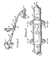
- a flailing line trimmer is shown in Figure 1 which flails a line in a circular path to trim grass and weeds.
- the device comprises an engine 10 mounted on the distal end of a hollow handle shaft 12 through which a flexible power transmitting cable 49 (as shown in Figure 2) passes therethrough to drive head 14.
- Handle 16 permits maneuvering of the drive and flailing line structures.
- the hollow handle shaft 12 comprises a first handle shaft part 20 and a second handle shaft part 22 with handle shaft part 20 being joined to a hand grip 24 (as shown in Fig. 1) extending outwardly from the engine.
- Handle shaft part 22 is joined to drive head 14 at one end and is rotatably joined and secured in abutment with handle shaft part 20 by a releasable coupling 18.
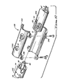
- Coupling 18 comprises a split clamp secured around the abutting ends of the two handle shaft parts by means of fasteners passing through mating flanges 28 and 30 on each end and opposite sides of the split clamp.
- Pin 32 mates with recess 34 in the end of handle shaft part 20 to prevent rotation of handle shaft part 20 relative to the clamp, and therefore relative to handle shaft part 22. It also prevents axial separation of handle shaft part 20 from the clamp when the clamp is tightened.
- Handle shaft part 22 has a circumferential groove 36 near its abutting end.
- Handle shaft part 20 can be the "upper” part, and handle shaft part 22 the “lower” part of the coupling or vice versa.
- Solid cylindrical inserts 42, 44 snugly fit in the hollow ends of the handle shaft parts inside coupling 18 to reinforce the shaft and resist compressive deformation when the clamp is tightened. Holes 46 through inserts 42, 44 permit passage of a cable guide tube 48 which may be formed of Nylon which journals the cable 49 that extends from engine 10 to drive head 14. Cable 49 is kept in central alignment by tube 48. The insert prevents the clamp from crushing the parts.
- handle shaft part 22 is fitted in the coupling until it abuts the end of handle shaft part 20, as viewed through port or hole 50 provided in the coupling. This also aligns lip 38 with groove 36 in handle shaft part 22. Pin 32 will be fitted into recess 34 in handle shaft part 20 before inserting handle shaft part 22. Their correct abutment can be assured by looking through the hole. The fasteners are then tightened down securely joining and clamping the two handle shaft parts together.
- the fasteners are bolt/nut combinations, with at least one of them adjacent to the groove being a wing nut 52 so it can be readily loosened and tightened.
- the wing nut will be tightened to fix the position of the drive head.
- Angular adjustment eliminates the difficult and tiring task of tilting and holding the drive head in opposition to a torque exerted by the cutting head or by the drive head.
- Fig. 6 discloses a handle shaft part 20A of an implement according to the invention.
- the handle shaft part 20A is provided with a slotted end 53 formed in a bayonet configuration, i.e., has a straight portion 54 and a laterally extending portion 55.
- This slot is engaged by a ridge 56 mounted to extend inwardly of the inside periphery of coupling 18A and longitudinally thereof, as shown in Figs. 8-10 when handle shaft part 20A is telescopically inserted into the left end of coupling 18a.
- Rotating handle shaft part 20a or the coupling a predetermined amount then moves ridge 56 into the laterally closed end portion 55 of slot 53 to interlock handle shaft part 20a and coupling 18a together.
- the other end of coupling 18a and its association with handle shaft part 22 is identical with the structure and operation of the parts and assembly shown in Figures 1-5 except that lip 38 is replaced with a pointed configuration 38' which fits within groove 36'.
- the implement head of the trimmer shown in Figures 6-9 may be replaced with a cultivator blade head, an air or snow blower implement or a small mower (not shown) and still fall within the scope of the claimed invention.
- Figures 10-12 disclose a further modification of the coupling for trimmer, cultivator, blower and mower implements shown in Figures 1-9 wherein like parts are given the same reference characters or the number with a "prime" designation if the part has been slightly modified such as inserts 42', 44', guide tube 48' and cable 49' and wherein handle shaft part 20, shown in Figures 1-5, is secured in abutment with handle shaft part 20a by a releasable coupling 18b.
- Coupling 18b includes a split clamp secured around the abutting ends of the two handle shaft parts by means of fasteners passing through mating flanges 28B and 30B on each side and opposite sides of the split clamp in the manner shown and described for Figs. 1-5.
- Pin 32 mates with recess 34 in the end of handle shaft part 20C to prevent rotation of handle shaft part 20C relative to the clamp and therefore relative to handle shaft part 20A.
- Handle shaft part 20A engages a ridge 56 mounted to extend inwardly of the inside periphery of coupling 18B and longitudinally thereof, as shown in Figs. 10-12, when handle shaft part 20A is telescopically inserted into the right end of coupling 18B. Rotating the handle shaft part 20C or the coupling a predetermined amount moves ridge 56 into the laterally closed end portion 55 of slot 53 to interlock handle shaft part 20A and coupling 18B together.
- flexible cable 49 is split or cut at a point within the coupling 18B and connectable when the coupling is assembled on the two parts of the handle shaft.
- cable49 comprises a connector 60, one part of which comprises a male end 61 which telescopically fits into a female end 62 of the other engageable part of cable 49 for engagement and disengagement purposes.
- a bayonet type connector is shown for purposes of illustration, any suitable make and break telescopic connection may be used for the flexible cable and still fall within the scope of this invention as claimed.
- a sight hole 50 may be provided in coupling 18B to note the abutment of handle shaft parts 20C and 20A, if so desired.
Landscapes
- Life Sciences & Earth Sciences (AREA)
- Environmental Sciences (AREA)
- Biodiversity & Conservation Biology (AREA)
- Ecology (AREA)
- Forests & Forestry (AREA)
- Engineering & Computer Science (AREA)
- Mechanical Engineering (AREA)
- Harvester Elements (AREA)
Claims (9)
Priority Applications (3)
| Application Number | Priority Date | Filing Date | Title |
|---|---|---|---|
| US06/549,804 US4505040A (en) | 1982-08-31 | 1983-11-09 | Coupling for interconnecting two handle portions of a power driven implement |
| DE8585301882T DE3577640D1 (de) | 1985-03-15 | 1985-03-15 | Kupplung zur verbindung zweier handgriffteile eines motorgeraets. |
| EP85301882A EP0195146B1 (de) | 1982-08-31 | 1985-03-15 | Kupplung zur Verbindung zweier Handgriffteile eines Motorgeräts |
Applications Claiming Priority (3)
| Application Number | Priority Date | Filing Date | Title |
|---|---|---|---|
| US06/413,521 US4463498A (en) | 1982-08-31 | 1982-08-31 | Coupling for flailing line trimmer handles |
| US06/549,804 US4505040A (en) | 1982-08-31 | 1983-11-09 | Coupling for interconnecting two handle portions of a power driven implement |
| EP85301882A EP0195146B1 (de) | 1982-08-31 | 1985-03-15 | Kupplung zur Verbindung zweier Handgriffteile eines Motorgeräts |
Publications (2)
| Publication Number | Publication Date |
|---|---|
| EP0195146A1 EP0195146A1 (de) | 1986-09-24 |
| EP0195146B1 true EP0195146B1 (de) | 1990-05-16 |
Family
ID=27228010
Family Applications (1)
| Application Number | Title | Priority Date | Filing Date |
|---|---|---|---|
| EP85301882A Expired - Lifetime EP0195146B1 (de) | 1982-08-31 | 1985-03-15 | Kupplung zur Verbindung zweier Handgriffteile eines Motorgeräts |
Country Status (2)
| Country | Link |
|---|---|
| US (1) | US4505040A (de) |
| EP (1) | EP0195146B1 (de) |
Families Citing this family (92)
| Publication number | Priority date | Publication date | Assignee | Title |
|---|---|---|---|---|
| US4505040A (en) * | 1982-08-31 | 1985-03-19 | Everts Robert G | Coupling for interconnecting two handle portions of a power driven implement |
| US5364307A (en) * | 1983-05-23 | 1994-11-15 | Vinylex Corporation | Coaxial drive cable centering apparatus |
| JPS60131117U (ja) * | 1984-02-14 | 1985-09-02 | 株式会社共立 | 刈払機の伝動装置 |
| DE3421999A1 (de) * | 1984-06-14 | 1986-01-09 | Fa. Andreas Stihl, 7050 Waiblingen | Reblaubschneidgeraet |
| US4654971A (en) * | 1985-09-13 | 1987-04-07 | Hudd Enterprises | Prunner with collapsible drive shaft and housing |
| GB8714817D0 (en) * | 1987-06-24 | 1987-07-29 | Flymo Ltd | Grass trimmer |
| US4829675A (en) * | 1987-08-19 | 1989-05-16 | The Toro Company | Electrical appliance and handle for same |
| JPH0531867Y2 (de) * | 1988-03-23 | 1993-08-17 | ||
| US4991298A (en) * | 1988-09-13 | 1991-02-12 | David K. Caruso | Extendible tree trimming apparatus |
| AU614548B2 (en) * | 1988-10-26 | 1991-09-05 | Tanaka Kogyo Co., Ltd. | Hand-held machine |
| US5013282A (en) * | 1989-11-20 | 1991-05-07 | Technic Tool Corporation | Extendible shaft assembly for portable tools |
| USD339591S (en) | 1991-07-09 | 1993-09-21 | Husqvarna Forest & Garden Ab | Support member for clearing saw |
| DE4223962C1 (de) * | 1992-07-21 | 1993-12-16 | Stihl Maschf Andreas | Freischneidegerät |
| US5367773A (en) * | 1993-06-24 | 1994-11-29 | Robbins; Everette P. | Rechargeable battery-powered tree pruning device |
| GB9323110D0 (en) * | 1993-11-09 | 1994-01-05 | Black & Decker Inc | Improved shaft assembly |
| US5603173A (en) * | 1994-01-28 | 1997-02-18 | Ryobi Outdoor Products Inc. | Snow thrower |
| GB2289610A (en) * | 1994-05-27 | 1995-11-29 | Ian Middleton Campbell | Hand held motorised garden cutting tool |
| GB9417851D0 (en) * | 1994-09-02 | 1994-10-26 | Goblin Ltd | Adjustable connection |
| US5802724A (en) * | 1994-09-09 | 1998-09-08 | Ryobi North America | Coupling for split-boom power tool |
| US5615970A (en) * | 1994-10-20 | 1997-04-01 | Black & Decker Inc. | String trimmer having knock-down handle |
| GB2297020B (en) * | 1995-01-21 | 1998-09-16 | Black & Decker Inc | Improvements in or relating to shaft assemblies |
| US5815928A (en) * | 1995-07-28 | 1998-10-06 | Wci Outdoor Products, Inc. | Portable powered lawn and garden tool |
| US5718050A (en) * | 1996-03-08 | 1998-02-17 | Technic Tool Corporation | Pruning cutter |
| DE19618025B4 (de) * | 1996-05-04 | 2009-02-26 | Fa. Andreas Stihl | Arbeitsgerät zum Entasten von Bäumen |
| DE19618024A1 (de) * | 1996-05-04 | 1997-11-06 | Stihl Maschf Andreas | Arbeitsgerät zum Entasten von Bäumen |
| DE19654348C1 (de) * | 1996-12-24 | 1998-11-19 | Stihl Maschf Andreas | Freischneidegerät mit einem teilbaren Führungsrohr |
| US6006434A (en) * | 1997-09-30 | 1999-12-28 | Hoffco, Inc. | Quick-release component connector for lawn tool |
| JP2916123B1 (ja) * | 1997-12-26 | 1999-07-05 | 川崎重工業株式会社 | 作業機における分離結合構造 |
| US6305867B1 (en) * | 1998-05-29 | 2001-10-23 | Andreas Stihl Ag & Co. | Connection for the sections of a separable guide tube and of a drive shaft disposed therein |
| DE19910793B4 (de) * | 1999-03-11 | 2009-11-26 | Andreas Stihl Ag & Co. | Arbeitsgerät |
| CN1149911C (zh) * | 1999-04-26 | 2004-05-19 | 刘昌喆 | 便携式树枝修剪器 |
| USD450226S1 (en) | 2000-02-03 | 2001-11-13 | The Toro Company | Vegetation trimmer |
| US6345489B1 (en) * | 2000-02-23 | 2002-02-12 | Mtd Southwest, Inc. | Wheeled lawn care unit |
| US6439088B1 (en) | 2000-04-25 | 2002-08-27 | The Toro Company | Reconfigurable vegetation trimmer and method of use |
| AU2001261301A1 (en) | 2000-05-09 | 2001-11-20 | Tennant Company | Cylindrical brush idler-side taper adjustment assembly |
| DE10050696B4 (de) * | 2000-10-13 | 2014-12-24 | Andreas Stihl Ag & Co. | Handgeführtes Arbeitsgerät, insbesondere Hochentaster |
| US6616489B1 (en) * | 2001-04-09 | 2003-09-09 | Denis R. Dompierre | Weed-trimmer adapted with a screw or water wheel |
| GB0112409D0 (en) * | 2001-05-22 | 2001-07-11 | Keane Stephen T | Edging attachment for weed strimmers |
| USD465623S1 (en) | 2001-06-18 | 2002-11-12 | Black & Decker Inc. | Vacuum cleaner |
| US6564423B2 (en) | 2001-06-21 | 2003-05-20 | Black & Decker Inc. | Two piece upright handle assembly for a vacuum cleaner system |
| USD463081S1 (en) | 2001-07-10 | 2002-09-17 | Black & Decker Inc. | Handle for a vacuum cleaner |
| SE523741C2 (sv) * | 2002-06-13 | 2004-05-11 | Electrolux Ab | Riggrör |
| AU764004B1 (en) * | 2002-06-19 | 2003-08-07 | Husqvarna Ab | Coupling device of free-cutting saw |
| US6997633B2 (en) * | 2002-09-30 | 2006-02-14 | Homelite Technologies, Ltd. | Coupling for split-boom power tool |
| ITVI20040157A1 (it) * | 2004-06-29 | 2004-09-29 | Positec Group Ltd | Elettroutensile con impugnatura ergonomica ed utensile rotativo |
| US7241084B2 (en) * | 2004-06-30 | 2007-07-10 | Omega Tools, Inc. | Tool assembly with universal coupling for various tools, for work on underground pipes |
| US7257909B2 (en) * | 2004-10-27 | 2007-08-21 | The Toro Company | Convertible yard tool |
| USD524824S1 (en) | 2004-10-27 | 2006-07-11 | The Toro Company | Convertible yard tool |
| US7314096B2 (en) * | 2004-10-27 | 2008-01-01 | The Toro Company | Adjustable handle for portable tool |
| USD519127S1 (en) | 2004-10-27 | 2006-04-18 | The Toro Company | Housing for convertible yard tool |
| GB0509745D0 (en) * | 2005-05-13 | 2005-06-22 | Black & Decker Inc | Vegetation trimmer |
| ITRE20050054A1 (it) * | 2005-05-17 | 2006-11-18 | Emak Spa | Sistema di innesto per connettere utensili da giardinaggio e simili ad un gruppo di potenza |
| CN100374255C (zh) * | 2005-09-29 | 2008-03-12 | 苏州宝时得电动工具有限公司 | 电圆锯 |
| US8579537B2 (en) * | 2006-07-05 | 2013-11-12 | Husqvarna Consumer Outdoor Products N.A., Inc. | Coupling arrangement |
| US7739800B2 (en) * | 2006-10-24 | 2010-06-22 | Hurley Edward P | Combination blower, trimmer and edger for tending vegetation |
| US20090025351A1 (en) * | 2007-07-26 | 2009-01-29 | Harry T. Faeldan | Tri-wheeled modular housing telescopic grass trimmer |
| RU2352105C1 (ru) * | 2007-08-27 | 2009-04-20 | Государственное научное учреждение Всероссийский научно-исследовательский институт гидротехники и мелиорации им. А.Н. Костякова Россельхозакадемии | Оросительная сеть для капельного орошения |
| US7597026B2 (en) * | 2007-11-29 | 2009-10-06 | Gm Global Technology Operations, Inc. | Cable assembly conduit condensation drain |
| US8020304B2 (en) * | 2008-02-13 | 2011-09-20 | Echo, Incorporated | Power transmission assembly for tool mounted on an elongate pole |
| US20100031515A1 (en) * | 2008-08-11 | 2010-02-11 | Edward Patrick Hurley | Grounds tool with means for transposable grips |
| DE202008011648U1 (de) * | 2008-09-02 | 2010-03-11 | Dolmar Gmbh | Kupplungselement |
| CN101722505B (zh) * | 2008-10-27 | 2014-12-10 | 南京德朔实业有限公司 | 动力工具 |
| USD621565S1 (en) | 2009-07-24 | 2010-08-10 | Martin Pierce | Cleaning head |
| USD652590S1 (en) | 2009-07-24 | 2012-01-17 | Kärcher North America, Inc. | Cleaning wand |
| US9414540B2 (en) * | 2010-03-24 | 2016-08-16 | Aero-Flex Technologies, Inc. | Oriented trimmer line |
| JP5525338B2 (ja) * | 2010-06-10 | 2014-06-18 | 株式会社マキタ | メインポールを有する作業機 |
| US20130161047A1 (en) * | 2010-09-13 | 2013-06-27 | Husqvarna Ab | Handle arrangement for a power tool |
| SE1000926A1 (sv) * | 2010-09-13 | 2012-02-28 | Anpassningsbar avverkningsmaskin | |
| JP5767955B2 (ja) * | 2011-12-01 | 2015-08-26 | 株式会社マキタ | 携帯型作業機 |
| US9009920B1 (en) * | 2012-08-02 | 2015-04-21 | Mark J. Ramsey | Motorized extension pole |
| US9119344B2 (en) * | 2013-02-05 | 2015-09-01 | The Toro Company | Reel mower having quick change grooming attachments |
| US9610678B2 (en) * | 2013-03-15 | 2017-04-04 | Mindflow Llc | Modular telescoping power pole and bar clamp/spreader tool |
| US9950776B2 (en) | 2013-10-22 | 2018-04-24 | Aqua Marine Products, L.L.C. | Weed-trimmer outboard motor |
| AU2014200377A1 (en) | 2014-01-22 | 2015-08-06 | GERBER, John Bruce Howard | A Connection Device or and Drive Assembly for a Cutting Tool |
| CN105519301B (zh) * | 2014-09-28 | 2019-04-19 | 南京德朔实业有限公司 | 打草机 |
| CN104718870A (zh) * | 2015-03-05 | 2015-06-24 | 安徽古德纳克科技股份有限公司 | 割草机 |
| WO2016150515A1 (en) * | 2015-03-26 | 2016-09-29 | Husqvarna Ab | Cutting device with pivoting working assembly |
| CN106914865B (zh) * | 2015-12-24 | 2019-11-22 | 南京德朔实业有限公司 | 手持式动力工具 |
| USD844423S1 (en) | 2015-10-08 | 2019-04-02 | John Gerber | Tool connector |
| CN206445757U (zh) * | 2016-12-23 | 2017-08-29 | 南京德朔实业有限公司 | 动力工具及其传动轴组件 |
| US10688647B2 (en) * | 2017-05-19 | 2020-06-23 | The Toro Company | Lawn and garden tool with boom having adjustable length and detachable boom sections |
| US11485003B2 (en) * | 2018-05-23 | 2022-11-01 | Milwaukee Electric Tool Corporation | Powerhead unit for tool |
| US11518018B2 (en) | 2019-01-21 | 2022-12-06 | Milwaukee Electric Tool Corporation | Power tool with non-conductive driveshaft |
| US11384719B2 (en) | 2019-03-15 | 2022-07-12 | Milwaukee Electric Tool Corporation | Fluid tank for a power tool |
| US10939612B2 (en) * | 2019-04-24 | 2021-03-09 | Anthony Lab | Weed wacker |
| US11618149B2 (en) | 2019-04-26 | 2023-04-04 | Milwaukee Electric Tool Corporation | Telescoping tool with collapsible bearing assembly |
| TWI697277B (zh) * | 2019-10-29 | 2020-07-01 | 臻禾興業有限公司 | 具辨識功能的園藝工具 |
| SE544150C2 (en) * | 2020-01-16 | 2022-01-11 | Husqvarna Ab | A vibration reducing handle for early entry concrete saws |
| JP7482004B2 (ja) * | 2020-11-26 | 2024-05-13 | 株式会社マキタ | 作業機 |
| US11697199B2 (en) * | 2021-02-24 | 2023-07-11 | Towa Industries, Incorporated | Power landscaping tool ensemble for using multiple tool heads |
| CN116352659A (zh) * | 2021-12-28 | 2023-06-30 | 创科无线普通合伙 | 作业工具及其传动系统 |
| US12599065B1 (en) * | 2024-12-09 | 2026-04-14 | Sihao Huang | Telescopic structure, telescopic blower, and telescopic electric chainsaw |
Family Cites Families (17)
| Publication number | Priority date | Publication date | Assignee | Title |
|---|---|---|---|---|
| US3006421A (en) * | 1961-10-31 | feilbach | ||
| US2550590A (en) * | 1942-03-12 | 1951-04-24 | Parmilleux Jean | Apparatus for the mechanical actuation of agricultural implements |
| US2553463A (en) * | 1947-04-05 | 1951-05-15 | Mcculloch Roger Lee | Removably attachable flexible reciprocating transmission and means for removably attaching reciprocating tools thereto |
| US2888994A (en) * | 1955-10-06 | 1959-06-02 | Hoffco Inc | Cultivating implement |
| US3605841A (en) * | 1970-03-24 | 1971-09-20 | Hormel & Co Geo A | Cutting device |
| US4052789A (en) * | 1976-12-02 | 1977-10-11 | Weed Eater, Inc. | Rotary cutting assembly |
| AT387491B (de) * | 1974-08-09 | 1989-01-25 | Wolf Geraete Gmbh | Motorgrasschere |
| US4122601A (en) * | 1976-02-06 | 1978-10-31 | Kaaz Machinery Co., Ltd. | Portable separable grass and bush cutter |
| CA1093843A (en) * | 1976-12-03 | 1981-01-20 | George C. Ballas, Sr. | Rotary cutting assembly |
| US4286675A (en) * | 1979-06-25 | 1981-09-01 | Beaird-Poulan Division Of Emerson Electric Co. | Narrow profile power handle for line trimmer and the like |
| US4364435A (en) * | 1980-12-22 | 1982-12-21 | Emerson Electric Co. | Lawn edger |
| US4451983A (en) * | 1979-11-19 | 1984-06-05 | Emerson Electric Co. | Plastic flexible shaft support |
| US4421176A (en) * | 1980-11-24 | 1983-12-20 | Emerson Electric Co. | Portable power operated cultivator with axially adjustable shield |
| US4391041A (en) * | 1981-04-20 | 1983-07-05 | The Toro Company | Powered ground care implement |
| US4463498A (en) * | 1982-08-31 | 1984-08-07 | Everts Robert G | Coupling for flailing line trimmer handles |
| US4505040A (en) * | 1982-08-31 | 1985-03-19 | Everts Robert G | Coupling for interconnecting two handle portions of a power driven implement |
| GB2125668B (en) * | 1982-08-31 | 1985-12-18 | Piston Powered Products Inc | Flailing line trimmers |
-
1983
- 1983-11-09 US US06/549,804 patent/US4505040A/en not_active Expired - Lifetime
-
1985
- 1985-03-15 EP EP85301882A patent/EP0195146B1/de not_active Expired - Lifetime
Also Published As
| Publication number | Publication date |
|---|---|
| EP0195146A1 (de) | 1986-09-24 |
| US4505040A (en) | 1985-03-19 |
Similar Documents
| Publication | Publication Date | Title |
|---|---|---|
| EP0195146B1 (de) | Kupplung zur Verbindung zweier Handgriffteile eines Motorgeräts | |
| US4463498A (en) | Coupling for flailing line trimmer handles | |
| US6006434A (en) | Quick-release component connector for lawn tool | |
| EP2773178B1 (de) | Vorrichtung zur verstellung der griffhöhe eines handgeführten elektrowerkzeugs, griffanordnung und handgeführtes elektrowerkzeug mit einer solchen vorrichtung | |
| US6474747B2 (en) | Split boom coupling structure | |
| US7624998B2 (en) | Handle height adjustment for walk behind mower | |
| US4936886A (en) | Wheel mounted string trimmer | |
| US6701623B2 (en) | Collapsable transverse handle for elongated tool | |
| US5996234A (en) | String trimmer guard | |
| US4733471A (en) | Tool drive assembly and clamp | |
| US4829755A (en) | Trimmer wheels | |
| US6370854B1 (en) | Guard and dolly for line trimming apparatus | |
| EP0893206A1 (de) | Einrichtung zur Justierung der relativen Position zweier Teile, insbesondere einem Hauptgriff und einem Zusatzhandgriff an einem Handwerkzeug | |
| US7913401B2 (en) | Three-in one trimmer head | |
| EP3533313B1 (de) | Koppler für elektrowerkzeug mit getrenntem ausleger | |
| US6779325B1 (en) | Edging and trimming assembly for lawn mower | |
| US6345489B1 (en) | Wheeled lawn care unit | |
| US20120167399A1 (en) | Edge-trimmer | |
| EP0263116A1 (de) | Erweiterbare handgriffe für heckenschere | |
| US20030230418A1 (en) | Rotary cutting device with quick-release blades | |
| US7584542B2 (en) | Trimmer | |
| US4854115A (en) | Apparatus for cutting grass and the like | |
| US5815928A (en) | Portable powered lawn and garden tool | |
| EP1415524B1 (de) | Fadenschneider | |
| EP1623615B1 (de) | Gartengerätverstellung |
Legal Events
| Date | Code | Title | Description |
|---|---|---|---|
| PUAI | Public reference made under article 153(3) epc to a published international application that has entered the european phase |
Free format text: ORIGINAL CODE: 0009012 |
|
| AK | Designated contracting states |
Kind code of ref document: A1 Designated state(s): DE GB IT SE |
|
| 17P | Request for examination filed |
Effective date: 19870116 |
|
| R17P | Request for examination filed (corrected) |
Effective date: 19870206 |
|
| RAP1 | Party data changed (applicant data changed or rights of an application transferred) |
Owner name: INERTIA DYNAMICS CORPORATION |
|
| RIN1 | Information on inventor provided before grant (corrected) |
Inventor name: EVERTS, ROBERT GUNNAR |
|
| 17Q | First examination report despatched |
Effective date: 19880509 |
|
| GRAA | (expected) grant |
Free format text: ORIGINAL CODE: 0009210 |
|
| AK | Designated contracting states |
Kind code of ref document: B1 Designated state(s): DE GB IT SE |
|
| ITF | It: translation for a ep patent filed | ||
| REF | Corresponds to: |
Ref document number: 3577640 Country of ref document: DE Date of ref document: 19900621 |
|
| PLBE | No opposition filed within time limit |
Free format text: ORIGINAL CODE: 0009261 |
|
| STAA | Information on the status of an ep patent application or granted ep patent |
Free format text: STATUS: NO OPPOSITION FILED WITHIN TIME LIMIT |
|
| PG25 | Lapsed in a contracting state [announced via postgrant information from national office to epo] |
Ref country code: GB Effective date: 19910315 |
|
| PG25 | Lapsed in a contracting state [announced via postgrant information from national office to epo] |
Ref country code: SE Effective date: 19910316 |
|
| 26N | No opposition filed | ||
| GBPC | Gb: european patent ceased through non-payment of renewal fee | ||
| EUG | Se: european patent has lapsed |
Ref document number: 85301882.8 Effective date: 19911009 |
|
| PGFP | Annual fee paid to national office [announced via postgrant information from national office to epo] |
Ref country code: DE Payment date: 19950322 Year of fee payment: 11 |
|
| PG25 | Lapsed in a contracting state [announced via postgrant information from national office to epo] |
Ref country code: DE Effective date: 19961203 |