EP0194960B1 - Umlaufregal - Google Patents
Umlaufregal Download PDFInfo
- Publication number
- EP0194960B1 EP0194960B1 EP86730017A EP86730017A EP0194960B1 EP 0194960 B1 EP0194960 B1 EP 0194960B1 EP 86730017 A EP86730017 A EP 86730017A EP 86730017 A EP86730017 A EP 86730017A EP 0194960 B1 EP0194960 B1 EP 0194960B1
- Authority
- EP
- European Patent Office
- Prior art keywords
- electric drive
- rocker
- shelf according
- revolving shelf
- chain
- Prior art date
- Legal status (The legal status is an assumption and is not a legal conclusion. Google has not performed a legal analysis and makes no representation as to the accuracy of the status listed.)
- Expired
Links
Images



Classifications
-
- B—PERFORMING OPERATIONS; TRANSPORTING
- B65—CONVEYING; PACKING; STORING; HANDLING THIN OR FILAMENTARY MATERIAL
- B65G—TRANSPORT OR STORAGE DEVICES, e.g. CONVEYORS FOR LOADING OR TIPPING, SHOP CONVEYOR SYSTEMS OR PNEUMATIC TUBE CONVEYORS
- B65G23/00—Driving gear for endless conveyors; Belt- or chain-tensioning arrangements
- B65G23/22—Arrangements or mountings of driving motors
-
- B—PERFORMING OPERATIONS; TRANSPORTING
- B65—CONVEYING; PACKING; STORING; HANDLING THIN OR FILAMENTARY MATERIAL
- B65G—TRANSPORT OR STORAGE DEVICES, e.g. CONVEYORS FOR LOADING OR TIPPING, SHOP CONVEYOR SYSTEMS OR PNEUMATIC TUBE CONVEYORS
- B65G1/00—Storing articles, individually or in orderly arrangement, in warehouses or magazines
- B65G1/02—Storage devices
- B65G1/04—Storage devices mechanical
- B65G1/12—Storage devices mechanical with separate article supports or holders movable in a closed circuit to facilitate insertion or removal of articles the articles being books, documents, forms or the like
- B65G1/127—Storage devices mechanical with separate article supports or holders movable in a closed circuit to facilitate insertion or removal of articles the articles being books, documents, forms or the like the circuit being confined in a vertical plane
-
- B—PERFORMING OPERATIONS; TRANSPORTING
- B65—CONVEYING; PACKING; STORING; HANDLING THIN OR FILAMENTARY MATERIAL
- B65G—TRANSPORT OR STORAGE DEVICES, e.g. CONVEYORS FOR LOADING OR TIPPING, SHOP CONVEYOR SYSTEMS OR PNEUMATIC TUBE CONVEYORS
- B65G43/00—Control devices, e.g. for safety, warning or fault-correcting
- B65G43/02—Control devices, e.g. for safety, warning or fault-correcting detecting dangerous physical condition of load carriers, e.g. for interrupting the drive in the event of overheating
Definitions
- the invention relates to a circulation rack with a plurality of objects to be stored, along a closed path movable by a chain driven by an electric drive load carriers, in which the electric drive against the force of at least one elastically deformable abutment is pivotally supported by limited amounts.
- a circulation rack of the type under consideration in which the electric motor is provided with a continuous shaft, the two ends of which are oscillating in opposite side walls of a housing, elastic abutments restricting the oscillating movements dampen.
- the oscillating suspension of the electric motor which is preferably designed as a geared motor, is intended to protect it from undesired vibrations.
- the known construction does not offer a possibility of recognizing whether the shelf is unevenly or even excessively loaded, although such a possibility of recognition would be in the interest of the user.
- the object of the invention is to provide a circulation rack of the type under consideration, in which it is possible with simple means to recognize whether the rack is unevenly or excessively loaded.
- This object is achieved according to the invention in that at least one displacement, angle or force measuring sensor, in particular in the form of a limit value sensor, is provided, that the sensor serves to detect the swiveling movements of the electric drive and that the forces introduced by the electric drive into the chain can be limited by the sensor.
- the circulation rack according to the invention offers considerable advantages. Asymmetrical loads are recognizable and can therefore be switched off. Overloading of the rack can also be prevented by adjusting the sensor so that it makes it impossible to start the electric motor if it is overloaded. In addition, there is a guarantee that in the event of malfunctions, e.g. B. stuck due to a broken component, the electric drive is automatically switched off. Finally, the elastically deformable abutments compensate for jerky movements, such as occur primarily when the load carriers start up on rotating shelves driven by a three-phase motor.
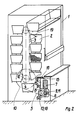
- Fig. 1 is the housing of a circulating rack equipped with a plurality of load carriers 2.
- a closed chain 3 which is directly connected to the individual load carriers, which are guided in guides (not shown), is used to drive the load carriers 2 along a path.
- the drive sprocket 10 for the chain is connected via a drive chain 5 to the output shaft 6 of the electric drive 7 designed as a geared motor, specifically via a sprocket attached to the output shaft 6.
- the electric drive 7 is mounted on a rocker 8, which is pivotable about the pivot point 9.
- the pivot point 9 of the rocker 8 lies outside the longitudinal axis 11 of the output shaft 6 of the electric drive 7.
- the rocker 8 is formed in the illustrated embodiment as a two-armed lever, the ends of which are supported by elastic abutments 13 formed by spring elements.
- a rocker arm 14 and a two-way switch, which serves as a limit value sensor 15, are assigned to the rocker 8.
- the forces F a of the left part of the chain 3 form a resultant F
- the forces F b of the right part form a resultant F 2 .
- the forces F and F 2 are the same, ie the torque to be applied by the electric drive 7 is low. If F deviates from F 2 , then the electric drive 7 must apply an additional torque in order to overcome the differential force. If the differential force is very large, the rocker 8 executes a pivoting movement about its pivot point 9 which is so large that there is contact between the rocker 8 and the two-way switch 15. If this happens, the motor 7 is automatically switched off. In other words, the two-way switch 15 forms a limit value sensor which can be set to the maximum permissible “unload”.
- the structure of the circulation rack shown in FIGS. 2-4 corresponds essentially to the structure of the circulation rack according to FIG. 1, except that the load carrier 2 is indirectly connected to the load chain 3 via support arms 19.
- the same reference numerals have therefore been used for the same parts.
- the pivot point 9 of the rocker 8 and the longitudinal axis 11 of the output shaft 6 coincide in this variant. It is one Particularly advantageous solution, since the drive chain 5 constantly maintains its position.
- force measuring sensors 18 have been added to the abutments formed by spring elements, which enable an asymmetry display of the loading state.
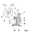
- FIG. 5 shows a further embodiment of an engine suspension.
- a rocker 8 is used, which is designed as a one-armed lever and whose arm 14 interacts with the switch 15.
- the boom is also guided between abutments 13 formed by spring elements.
- the springs can be embedded in rubber and thus act as damping elements at the same time.
- FIG. 6 is a further variant of a limit value sensor 15.
- a two-way switch is attached to the rocker 8. If the rocker 8 moves around the pivot point 9 so strongly that the limit sensor 15 comes into contact with the limiter, the motor is automatically switched off.
- FIG. 7 shows a further possibility of the measurement value acquisition for determining the asymmetry.
- the motor rocker 8 is mounted in the pivot point 9.
- the axis of rotation of the motor rocker is firmly connected to the rocker 8.
- An angle measuring sensor 17 is assigned to the end of the rocker axis and can detect the rotational movement of the shaft.
- the measurement signal can be evaluated to display the asymmetry, to indicate the direction of the asymmetry, to indicate the overload and to indicate the breakdown fault.
Landscapes
- Engineering & Computer Science (AREA)
- Mechanical Engineering (AREA)
- Warehouses Or Storage Devices (AREA)
- Transmission Devices (AREA)
- Centrifugal Separators (AREA)
Description
- Die Erfindung betrifft ein Umlaufregal mit einer Vielzahl von zur Aufnahme aufzubewahrender Gegenstände dienenden, längs einer geschlossenen Bahn durch eine von einem Elektroantrieb angetriebene Kette bewegbaren Lastträgern, bei dem der Elektroantrieb gegen die Kraft mindestens eines elastisch verformbaren Widerlagers um begrenzte Beträge schwenkbar gelagert ist.
- Aus der FR-A-2 269 887 ist ein Umlaufregal der in Betracht gezogenen Art bekannt, bei dem der Elektromotor mit einer durchgehenden Welle versehen ist, dessen beide Enden in sich gegenüberliegenden Seitenwänden eines Gehäuses pendelnd gelagert sind, wobei elastische Widerlager die Pendelbewegungen begrenzen bzw. dämpfen. Durch die pendelnde Aufhängung des vorzugsweise als Getriebemotor ausgebildeten Elektromotors soll dieser vor unerwünschten Schwingungen bewahrt werden. Eine Möglichkeit zum Erkennen, ob das Regal ungleich oder gar übermäßig beladen ist, bietet die bekannte Konstruktion nicht, wiewohl eine solche Erkennungsmöglichkeit durchaus im Interesse des Anwenders wäre.
- Aufgabe der Erfindung ist es, ein Umlaufregal der in Betracht gezogenen Art zu schaffen, bei dem es mit einfachen Mitteln möglich ist, zu erkennen, ob das Regal ungleich oder übermäßig beladen ist. Diese Aufgabe wird erfindungsgemäß dadurch gelöst, daß mindestens ein insbesondere als Grenzwertsensor ausgebildeter Weg-, Winkel-oder Kraftmeßsensor vorgesehen ist, daß der Sensor zum Erfassen der Schwenkbewegungen des Elektroantriebes dient und daß durch den Sensor die vom Elektroantrieb in die Kette eingeleiteten Kräfte begrenzbar sind.
- Das erfindungsgemäße Umlaufregal bietet erhebliche Vorteile. Unsymmetrische Belastungen sind erkennbar und folglich ausschaltbar. Auch ein Überladen des Regales läßt sich verhindern, indem man den Sensor so justiert, daß er das Anlaufen des Elektromotors bei Überladung unmöglich macht. Außerdem ist die Gewähr dafür gegeben, daß im Falle von Störungen, z. B. eines Festlaufens infolge eines gebrochenen Bauteiles, der Elektroantrieb automatisch abgeschaltet wird. Schließlich gleichen die elastisch verformbaren Widerlager ruckartige Bewegungen aus, wie sie vornehmlich beim Anlauf der Lastträger von durch einen Drehstrommotor angetriebenen Umlaufregalen auftreten.
- Weitere Einzelheiten ergeben sich aus den Unteransprüchen und der nachfolgenden Beschreibung zweier in der beigefügten Zeichnung dargestellter Ausführungsbeispiele. Es zeigen:
- Fig. 1 stark schematisiert die Ansicht eines ersten Umlaufregales;
- Fig. 2 ebenfalls stark schematisiert die Ansicht eines zweiten Umlaufregales;
- Fig. 3 die Motoraufhängung des Umlaufregales gemäß Fig. 2 im vergrößerten Maßstab;
- Fig. 4 eine Draufsicht auf die in Fig. 3 dargestellten Teile;
- Fig. 5 eine modifizierte Motoraufhängung;
- Fig. 6 die Motoraufhängung des Umlaufregales gemäß Fig. 1 im vergrößerten Maßstab mit modifizierter Darstellung der Dämpfung, Kraftmeßsensoren und Grenzwertsensoren und
- Fig. 7 eine Draufsicht auf die in Fig. 6 dargestellten Teile mit einer möglichen Zuordnung eines Winkelmeßsensors.
- In Fig. 1 ist 1 das Gehäuse eines mit mehreren Lastträgern 2 ausgerüsteten Umlaufregales. Zum Antrieb der Lastträger 2 längs einer Bahn dient eine geschlossene Kette 3, die mit den einzelnen Lastträgern, welche in nicht dargestellten Führungen geführt sind, direkt verbunden ist. Im dargestellten Ausführungsbeispiel steht das Antriebskettenrad 10 für die Kette über eine Antriebskette 5 mit der Abtriebswelle 6 des als Getriebemotor ausgebildeten Elektroantriebes 7 in Verbindung, und zwar über ein auf der Abtriebswelle 6 befestigtes Kettenrad. Der Elektroantrieb 7 ist auf einer Wippe 8 gelagert, die um den Drehpunkt 9 schwenkbar ist. Der Drehpunkt 9 der Wippe 8 liegt bei dem Ausführungsbeispiel gemäß Fig. 1 außerhalb der Längsachse 11. der Abtriebswelle 6 des Elektroantriebes 7.
- Die Wippe 8 ist im dargestellten Ausführungsbeispiel als zweiarmiger Hebel ausgebildet, dessen Enden durch von Federelementen gebildete elastische Widerlager 13 abgestützt werden. Der Wippe 8 sind ein Ausleger 14 und ein Zweiwegeschalter zugeordnet, der als Grenzwertsensor 15 dient.
- Die Kräfte Fa des linken Teils der Kette 3 bilden eine Resultierende F, und die Kräfte Fb des rechten Teils eine resultierende F2. Bei gleichmäßig beladenem Umlaufregal sind die Kräfte F, und F2 gleich, d. h. das vom Elektroantrieb 7 aufzubringende Drehmoment ist gering. Weicht F, von F2 ab, so muß der Elektroantrieb 7 ein zusätzliches Drehmoment aufbringen, um die Differenzkraft zu überwinden. Ist die Differenzkraft sehr groß, so führt die Wippe 8 eine Schwenkbewegung um ihren Drehpunkt 9 aus, die so groß ist, daß es zu einem Kontakt zwischen der Wippe 8 und dem Zweiwegeschalter 15 kommt. Tritt dieser Fall ein, so wird der Motor 7 automatisch abgeschaltet. Der Zweiwegeschalter 15 bildet mit anderen Worten einen Grenzwertsensor, der auf die maximal zulässige "Unlast" einstellbar ist.
- Der Aufbau des in den Fig. 2 - 4 dargestellten Umlaufregales entspricht im wesentlichen dem Aufbau des Umlaufregales gemäß Fig. 1, außer daß der Lastträger 2 indirekt über Tragarme 19 mit der Lastkette 3 verbunden ist. Für gleiche Teile wurden daher die gleichen Bezugszeichen verwendet. Anders als im ersten Ausführungsbeispiel fallen bei dieser Variante der Drehpunkt 9 der Wippe 8 und die Längsachse 11 der Abtriebswelle 6 zusammen. Es ist dies eine besonders vorteilhafte Lösung, da die Antriebskette 5 ihre Lage ständig beibehält. Ein weiterer Unterschied zwischen den beiden Konstruktionen besteht darin, daß beim zweiten Umlaufregal zu den von Federelementen gebildeten Widerlagern 13 Kraftmeßsensoren 18 hinzugekommen sind, die eine Unsymmetrieanzeige des Beladungszustandes ermöglichen.
- In Fig. 5 schließlich ist ein weiteres Ausführungsbeispiel einer Motoraufhängung dargestellt. In diesem Fall findet eine Wippe 8 Verwendung, die als einarmiger Hebel ausgebildet ist und dessen Ausleger 14 mit dem Schalter 15 zusammenwirkt. Der Ausleger ist zudem zwischen von Federelementen gebildeten Widerlagern 13 geführt. Die Federn können in Gummi eingebettet sein und somit gleichzeitig als Dämpfungselemente wirken. Eine solche Lösung bietet besondere Vorteile bei Verwendung eines Elektroantriebes 7 mit einem Drehstrommotor. Beim Einschalten eines Drehstrommotors erreicht dieser bekanntlich praktisch sofort seine Nenndrehzahl. Dies führt zu ruckartigen Anlaufbewegungen der Lastträger und des Lagergutes im Kurvenbereich. Den ruckartigen Bewegungen wird durch die Dämpfung entgegengewirkt.
- Fig. 6 ist eine weitere Variante eines Grenzwertsensors 15. Dabei ist ein Zweiwegeschalter an der Wippe 8 befestigt. Bewegt sich die Wippe 8 um den Drehpunkt 9 so stark, daß der Grenzwertsensor 15 Kontakt mit dem Begrenzer bekommt, so wird der Motor automatisch abgeschaltet.
- Fig. 7 stellt eine weitere Möglichkeit der Meßwerterfassung zur Ermittlung der Unsymmetrie dar. Die Motorwippe 8 ist im Drehpunkt 9 gelagert. Die Drehachse der Motorwippe ist fest mit der Wippe 8 verbunden. Dem Ende der Wippenachse ist ein Winkelmeßsensor 17 zugeordnet, der die Drehbewegung der Welle erfassen kann. Das Meßsignal kann zur Anzeige der Unsymmetrie, zur Richtungsanzeige der Unsymmetrie, zur Überladungsanzeige und zur Bruchstörungsanzeige ausgewertet werden.
Claims (9)
Priority Applications (1)
| Application Number | Priority Date | Filing Date | Title |
|---|---|---|---|
| AT86730017T ATE33372T1 (de) | 1985-02-08 | 1986-01-31 | Umlaufregal. |
Applications Claiming Priority (2)
| Application Number | Priority Date | Filing Date | Title |
|---|---|---|---|
| DE19853504751 DE3504751A1 (de) | 1985-02-08 | 1985-02-08 | Umlaufregal |
| DE3504751 | 1985-02-08 |
Publications (2)
| Publication Number | Publication Date |
|---|---|
| EP0194960A1 EP0194960A1 (de) | 1986-09-17 |
| EP0194960B1 true EP0194960B1 (de) | 1988-04-06 |
Family
ID=6262301
Family Applications (1)
| Application Number | Title | Priority Date | Filing Date |
|---|---|---|---|
| EP86730017A Expired EP0194960B1 (de) | 1985-02-08 | 1986-01-31 | Umlaufregal |
Country Status (5)
| Country | Link |
|---|---|
| US (1) | US4676560A (de) |
| EP (1) | EP0194960B1 (de) |
| JP (1) | JPS61188307A (de) |
| AT (1) | ATE33372T1 (de) |
| DE (2) | DE3504751A1 (de) |
Families Citing this family (27)
| Publication number | Priority date | Publication date | Assignee | Title |
|---|---|---|---|---|
| DE3731871A1 (de) * | 1987-09-18 | 1989-04-06 | Bellheimer Metallwerk Gmbh | Umlaufregal |
| DE3825401A1 (de) * | 1988-07-22 | 1990-01-25 | Bellheimer Metallwerk Gmbh | Umlaufregal |
| EP0392275A1 (de) * | 1989-04-13 | 1990-10-17 | Gebr. Hennig GmbH | Späneförderer |
| DE3921105A1 (de) * | 1989-06-28 | 1991-01-10 | Karosseriebau Heinrichs Gmbh | Fahrbarer warenbehaelter |
| US5040689A (en) * | 1990-05-23 | 1991-08-20 | Hull Harold L | Rotating filing cabinet |
| JPH063915U (ja) * | 1991-03-15 | 1994-01-18 | 直志 中津 | 物品格納装置における事故発生防止装置 |
| JPH0549713U (ja) * | 1991-03-29 | 1993-06-29 | 村田機械株式会社 | パッケージ収容装置 |
| DE4311695C2 (de) * | 1992-05-22 | 1995-03-30 | Haenel Gmbh & Co Kg | Vorrichtung zur Messung der Traglasten in einem Paternosterschrank |
| EP0570912A1 (de) * | 1992-05-22 | 1993-11-24 | HÄNEL & CO. | Vorrichtung zur Messung der Traglasten in einem Paternosterschrank |
| FR2737018B1 (fr) * | 1995-07-20 | 1997-08-14 | Alcatel Submarcom | Procede d'injection controlee d'une matiere de remplissage dans un tube de protection de fibres optiques et installation de mise en oeuvre du procede |
| US5738225A (en) * | 1996-10-21 | 1998-04-14 | Kim; Bongki | Device in which a bookrack moves vertically and horizontally |
| DE10200513B4 (de) * | 2002-01-09 | 2005-07-28 | Pfeifer Seil- Und Hebetechnik Gmbh | Greifvorrichtung |
| EP2790210A3 (de) | 2002-06-19 | 2014-12-31 | Murata Machinery, Ltd. | Automatisiertes Materialhandhabungssystem |
| US6729482B1 (en) * | 2002-10-09 | 2004-05-04 | The Boeing Company | Automated storage and retrieval system |
| US10957569B2 (en) | 2002-10-11 | 2021-03-23 | Murata Machinery Ltd. | Access to one or more levels of material storage shelves by an overhead hoist transport vehicle from a single track position |
| EP1475320A3 (de) * | 2003-05-02 | 2006-02-08 | Loh Engineering Ag | Container für eine Produktionsstätte zur Fertigung von individuellen Brillengläsern |
| US20080298943A1 (en) * | 2007-06-01 | 2008-12-04 | Siegel Cynthia L | Postal-Go-Round |
| US7811042B1 (en) * | 2007-06-12 | 2010-10-12 | Manuel J Menendez | Vertical carousel for lumber |
| JP5985385B2 (ja) * | 2012-12-27 | 2016-09-06 | 住友重機械工業株式会社 | ギヤモータ |
| CN203283717U (zh) * | 2013-03-29 | 2013-11-13 | 欧神助 | 高、多层仓储及种养回转型机械 |
| AT514743B1 (de) * | 2013-09-13 | 2017-12-15 | Blum Gmbh Julius | Vorrichtung zur Bewegung eines Möbelteils |
| US9239105B2 (en) * | 2013-10-11 | 2016-01-19 | Kone Corporation | Power transmission system for people mover |
| US10450137B2 (en) * | 2014-12-04 | 2019-10-22 | Brian O'Connell | Rotating vertical storage system for barrels |
| KR101868825B1 (ko) * | 2016-05-25 | 2018-06-19 | 나정환 | 스마트 저장고 |
| EP3406559A1 (de) * | 2017-05-24 | 2018-11-28 | Otis Elevator Company | Personenförderer |
| EP3599212B1 (de) * | 2018-07-27 | 2024-06-12 | Otis Elevator Company | Fehlausrichtungsüberwachung des antriebs in einem personenförderer |
| US11266256B2 (en) * | 2019-12-17 | 2022-03-08 | Walmart Apollo, Llc | Expendable service surface device |
Family Cites Families (7)
| Publication number | Priority date | Publication date | Assignee | Title |
|---|---|---|---|---|
| GB714835A (en) * | 1950-02-11 | 1954-09-01 | Samuel Davis Robins | Improvements in or relating to conveyor systems |
| US2940810A (en) * | 1957-11-21 | 1960-06-14 | Diebold Inc | Elevator filing appliance |
| US3720451A (en) * | 1971-06-21 | 1973-03-13 | Diebold Inc | Power file construction |
| FR2269887A1 (en) * | 1974-05-08 | 1975-12-05 | Wolff Andre | Rotary filing system using swinging boxes - has two endless box support chains with lower drive pinions |
| FR2347906A2 (fr) * | 1976-04-14 | 1977-11-10 | Wolff Andre | Appareil de classement rotatif a chaines sans fin |
| US4175657A (en) * | 1978-01-13 | 1979-11-27 | Jervis B. Webb Company | Drive unit for a conveyor chain |
| DE8117837U1 (de) * | 1981-06-19 | 1982-06-24 | Siegfried Hartert Werksvertretungen und Großhandel in Einrichtungen und Textilwaren für Krankenhäuser, Behörden und Großverbraucher, 7250 Leonberg | Schrank, insbesondere waescheschrank |
-
1985
- 1985-02-08 DE DE19853504751 patent/DE3504751A1/de active Granted
-
1986
- 1986-01-31 DE DE8686730017T patent/DE3660118D1/de not_active Expired
- 1986-01-31 AT AT86730017T patent/ATE33372T1/de not_active IP Right Cessation
- 1986-01-31 EP EP86730017A patent/EP0194960B1/de not_active Expired
- 1986-02-04 US US06/825,808 patent/US4676560A/en not_active Expired - Fee Related
- 1986-02-07 JP JP61025646A patent/JPS61188307A/ja active Granted
Also Published As
| Publication number | Publication date |
|---|---|
| ATE33372T1 (de) | 1988-04-15 |
| DE3504751C2 (de) | 1987-05-21 |
| EP0194960A1 (de) | 1986-09-17 |
| DE3660118D1 (en) | 1988-05-11 |
| JPS61188307A (ja) | 1986-08-22 |
| JPH0241485B2 (de) | 1990-09-18 |
| DE3504751A1 (de) | 1986-08-14 |
| US4676560A (en) | 1987-06-30 |
Similar Documents
| Publication | Publication Date | Title |
|---|---|---|
| DE3504751C2 (de) | ||
| DE3235224C2 (de) | ||
| EP0014730B1 (de) | Sicherheitseinrichtung für eine spindelbetriebene Hebeeinrichtung, insbesondere Zwei-Säulen-Kraftfahrzeug-Hebebühne | |
| DE69414089T2 (de) | Gelenkroboter | |
| DE3631946A1 (de) | Elektrisch betriebene, schwenkbare fahrzeuglenkvorrichtung | |
| DE69500404T2 (de) | Waage, insbesondere Badezimmer-Waage und Verfahren zur Montage | |
| EP0016998A1 (de) | Hubvorrichtung, insbesondere Hebebühne | |
| EP3812304A1 (de) | Vorrichtung zur wegmessung und/oder positionsbestimmung eines in einer logistikanlage eingesetzten fahrzeugs und kanalfahrzeuge | |
| DE2132067A1 (de) | Elektrisch antreibbarer fensterheber | |
| DE10249031A1 (de) | Bandförderer und Reinigungsvorrichtung | |
| DE3738434A1 (de) | Wischvorrichtung fuer scheiben von kraftfahrzeugen | |
| DE3112802A1 (de) | Aufhaengung fuer den schwenkbar gelagerten bandantriebsmotor in einem kassettenmagnetbandgeraet | |
| DE3041826C2 (de) | ||
| DE3844359C2 (de) | Bandschleifer | |
| DE60037083T2 (de) | Wischervorrichtung | |
| EP0665422B1 (de) | Lastwägeeinrichtung mit seitlichem Anschlag und Wälzkörpern | |
| DE1171690B (de) | Hebelwerk zum Festhalten von einem durch ein Drehmoment beanspruchten Maschinenteil | |
| DE202019102262U1 (de) | Abschaltpuffer für ein Hebezeug, insbesondere Kettenzug, und Hebezeug hiermit | |
| EP1327600B1 (de) | Greifvorrichtung | |
| DE3613580A1 (de) | Vorrichtung zum antrieb eines seitwaerts beweglichen korrekturgliedes in einer anlage zur korrektur der seitwaertsbewegung eines druchlaufenden flachen bandmaterials | |
| DE2512791A1 (de) | Ueberlastschalteinrichtung fuer antriebe von fahrzeugteleskopantennen | |
| DE1276556B (de) | Lager fuer Uhrwerke | |
| DE69410444T2 (de) | Anpressfeder für einen scheibenwischerarm | |
| DE8500847U1 (de) | Antrieb für einen Kreiselmäher | |
| DE1455811C (de) | Radlenkeranordnung fur Kraftfahr zeuge |
Legal Events
| Date | Code | Title | Description |
|---|---|---|---|
| PUAI | Public reference made under article 153(3) epc to a published international application that has entered the european phase |
Free format text: ORIGINAL CODE: 0009012 |
|
| AK | Designated contracting states |
Kind code of ref document: A1 Designated state(s): AT BE CH DE FR GB IT LI NL SE |
|
| 17P | Request for examination filed |
Effective date: 19861030 |
|
| 17Q | First examination report despatched |
Effective date: 19870602 |
|
| GRAA | (expected) grant |
Free format text: ORIGINAL CODE: 0009210 |
|
| AK | Designated contracting states |
Kind code of ref document: B1 Designated state(s): AT BE CH DE FR GB IT LI NL SE |
|
| REF | Corresponds to: |
Ref document number: 33372 Country of ref document: AT Date of ref document: 19880415 Kind code of ref document: T |
|
| GBT | Gb: translation of ep patent filed (gb section 77(6)(a)/1977) | ||
| REF | Corresponds to: |
Ref document number: 3660118 Country of ref document: DE Date of ref document: 19880511 |
|
| ET | Fr: translation filed | ||
| ITF | It: translation for a ep patent filed | ||
| PLBE | No opposition filed within time limit |
Free format text: ORIGINAL CODE: 0009261 |
|
| 26N | No opposition filed | ||
| ITTA | It: last paid annual fee | ||
| PGFP | Annual fee paid to national office [announced via postgrant information from national office to epo] |
Ref country code: FR Payment date: 19921216 Year of fee payment: 8 |
|
| PGFP | Annual fee paid to national office [announced via postgrant information from national office to epo] |
Ref country code: DE Payment date: 19930122 Year of fee payment: 8 Ref country code: SE Payment date: 19930122 Year of fee payment: 8 |
|
| PGFP | Annual fee paid to national office [announced via postgrant information from national office to epo] |
Ref country code: AT Payment date: 19930126 Year of fee payment: 8 |
|
| PGFP | Annual fee paid to national office [announced via postgrant information from national office to epo] |
Ref country code: GB Payment date: 19930128 Year of fee payment: 8 |
|
| PGFP | Annual fee paid to national office [announced via postgrant information from national office to epo] |
Ref country code: NL Payment date: 19930131 Year of fee payment: 8 |
|
| PGFP | Annual fee paid to national office [announced via postgrant information from national office to epo] |
Ref country code: BE Payment date: 19930204 Year of fee payment: 8 |
|
| PGFP | Annual fee paid to national office [announced via postgrant information from national office to epo] |
Ref country code: CH Payment date: 19930217 Year of fee payment: 8 |
|
| PG25 | Lapsed in a contracting state [announced via postgrant information from national office to epo] |
Ref country code: CH Effective date: 19940131 Ref country code: AT Effective date: 19940131 Ref country code: BE Effective date: 19940131 Ref country code: GB Effective date: 19940131 Ref country code: LI Effective date: 19940131 |
|
| PG25 | Lapsed in a contracting state [announced via postgrant information from national office to epo] |
Ref country code: SE Effective date: 19940201 |
|
| BERE | Be: lapsed |
Owner name: BELLHEIMER METALLWERK G.M.B.H. Effective date: 19940131 |
|
| PG25 | Lapsed in a contracting state [announced via postgrant information from national office to epo] |
Ref country code: NL Effective date: 19940801 |
|
| NLV4 | Nl: lapsed or anulled due to non-payment of the annual fee | ||
| GBPC | Gb: european patent ceased through non-payment of renewal fee |
Effective date: 19940131 |
|
| PG25 | Lapsed in a contracting state [announced via postgrant information from national office to epo] |
Ref country code: FR Effective date: 19940930 |
|
| REG | Reference to a national code |
Ref country code: CH Ref legal event code: PL |
|
| PG25 | Lapsed in a contracting state [announced via postgrant information from national office to epo] |
Ref country code: DE Effective date: 19941001 |
|
| REG | Reference to a national code |
Ref country code: FR Ref legal event code: ST |
|
| EUG | Se: european patent has lapsed |
Ref document number: 86730017.0 Effective date: 19940910 |
|
| PG25 | Lapsed in a contracting state [announced via postgrant information from national office to epo] |
Ref country code: IT Free format text: LAPSE BECAUSE OF NON-PAYMENT OF DUE FEES;WARNING: LAPSES OF ITALIAN PATENTS WITH EFFECTIVE DATE BEFORE 2007 MAY HAVE OCCURRED AT ANY TIME BEFORE 2007. THE CORRECT EFFECTIVE DATE MAY BE DIFFERENT FROM THE ONE RECORDED. Effective date: 20050131 |