EP0191179B1 - Thermoakustische Vorrichtung - Google Patents
Thermoakustische Vorrichtung Download PDFInfo
- Publication number
- EP0191179B1 EP0191179B1 EP85115760A EP85115760A EP0191179B1 EP 0191179 B1 EP0191179 B1 EP 0191179B1 EP 85115760 A EP85115760 A EP 85115760A EP 85115760 A EP85115760 A EP 85115760A EP 0191179 B1 EP0191179 B1 EP 0191179B1
- Authority
- EP
- European Patent Office
- Prior art keywords
- rod
- elements
- thermoacoustic device
- thermoacoustic
- bar elements
- Prior art date
- Legal status (The legal status is an assumption and is not a legal conclusion. Google has not performed a legal analysis and makes no representation as to the accuracy of the status listed.)
- Expired
Links
- 230000003534 oscillatory effect Effects 0.000 claims 6
- 230000010355 oscillation Effects 0.000 claims 1
- 238000005192 partition Methods 0.000 description 2
- 238000011161 development Methods 0.000 description 1
- 230000018109 developmental process Effects 0.000 description 1
- 238000005457 optimization Methods 0.000 description 1
- 239000010409 thin film Substances 0.000 description 1
- 238000003466 welding Methods 0.000 description 1
Images
Classifications
-
- F—MECHANICAL ENGINEERING; LIGHTING; HEATING; WEAPONS; BLASTING
- F02—COMBUSTION ENGINES; HOT-GAS OR COMBUSTION-PRODUCT ENGINE PLANTS
- F02G—HOT GAS OR COMBUSTION-PRODUCT POSITIVE-DISPLACEMENT ENGINE PLANTS; USE OF WASTE HEAT OF COMBUSTION ENGINES; NOT OTHERWISE PROVIDED FOR
- F02G1/00—Hot gas positive-displacement engine plants
- F02G1/04—Hot gas positive-displacement engine plants of closed-cycle type
- F02G1/043—Hot gas positive-displacement engine plants of closed-cycle type the engine being operated by expansion and contraction of a mass of working gas which is heated and cooled in one of a plurality of constantly communicating expansible chambers, e.g. Stirling cycle type engines
- F02G1/053—Component parts or details
- F02G1/057—Regenerators
-
- F—MECHANICAL ENGINEERING; LIGHTING; HEATING; WEAPONS; BLASTING
- F25—REFRIGERATION OR COOLING; COMBINED HEATING AND REFRIGERATION SYSTEMS; HEAT PUMP SYSTEMS; MANUFACTURE OR STORAGE OF ICE; LIQUEFACTION SOLIDIFICATION OF GASES
- F25B—REFRIGERATION MACHINES, PLANTS OR SYSTEMS; COMBINED HEATING AND REFRIGERATION SYSTEMS; HEAT PUMP SYSTEMS
- F25B9/00—Compression machines, plants or systems, in which the refrigerant is air or other gas of low boiling point
- F25B9/14—Compression machines, plants or systems, in which the refrigerant is air or other gas of low boiling point characterised by the cycle used, e.g. Stirling cycle
- F25B9/145—Compression machines, plants or systems, in which the refrigerant is air or other gas of low boiling point characterised by the cycle used, e.g. Stirling cycle pulse-tube cycle
-
- F—MECHANICAL ENGINEERING; LIGHTING; HEATING; WEAPONS; BLASTING
- F02—COMBUSTION ENGINES; HOT-GAS OR COMBUSTION-PRODUCT ENGINE PLANTS
- F02G—HOT GAS OR COMBUSTION-PRODUCT POSITIVE-DISPLACEMENT ENGINE PLANTS; USE OF WASTE HEAT OF COMBUSTION ENGINES; NOT OTHERWISE PROVIDED FOR
- F02G2243/00—Stirling type engines having closed regenerative thermodynamic cycles with flow controlled by volume changes
- F02G2243/30—Stirling type engines having closed regenerative thermodynamic cycles with flow controlled by volume changes having their pistons and displacers each in separate cylinders
- F02G2243/50—Stirling type engines having closed regenerative thermodynamic cycles with flow controlled by volume changes having their pistons and displacers each in separate cylinders having resonance tubes
- F02G2243/54—Stirling type engines having closed regenerative thermodynamic cycles with flow controlled by volume changes having their pistons and displacers each in separate cylinders having resonance tubes thermo-acoustic
-
- F—MECHANICAL ENGINEERING; LIGHTING; HEATING; WEAPONS; BLASTING
- F25—REFRIGERATION OR COOLING; COMBINED HEATING AND REFRIGERATION SYSTEMS; HEAT PUMP SYSTEMS; MANUFACTURE OR STORAGE OF ICE; LIQUEFACTION SOLIDIFICATION OF GASES
- F25B—REFRIGERATION MACHINES, PLANTS OR SYSTEMS; COMBINED HEATING AND REFRIGERATION SYSTEMS; HEAT PUMP SYSTEMS
- F25B2309/00—Gas cycle refrigeration machines
- F25B2309/14—Compression machines, plants or systems characterised by the cycle used
- F25B2309/1407—Pulse-tube cycles with pulse tube having in-line geometrical arrangements
-
- F—MECHANICAL ENGINEERING; LIGHTING; HEATING; WEAPONS; BLASTING
- F25—REFRIGERATION OR COOLING; COMBINED HEATING AND REFRIGERATION SYSTEMS; HEAT PUMP SYSTEMS; MANUFACTURE OR STORAGE OF ICE; LIQUEFACTION SOLIDIFICATION OF GASES
- F25B—REFRIGERATION MACHINES, PLANTS OR SYSTEMS; COMBINED HEATING AND REFRIGERATION SYSTEMS; HEAT PUMP SYSTEMS
- F25B2309/00—Gas cycle refrigeration machines
- F25B2309/14—Compression machines, plants or systems characterised by the cycle used
- F25B2309/1416—Pulse-tube cycles characterised by regenerator stack details
-
- F—MECHANICAL ENGINEERING; LIGHTING; HEATING; WEAPONS; BLASTING
- F25—REFRIGERATION OR COOLING; COMBINED HEATING AND REFRIGERATION SYSTEMS; HEAT PUMP SYSTEMS; MANUFACTURE OR STORAGE OF ICE; LIQUEFACTION SOLIDIFICATION OF GASES
- F25B—REFRIGERATION MACHINES, PLANTS OR SYSTEMS; COMBINED HEATING AND REFRIGERATION SYSTEMS; HEAT PUMP SYSTEMS
- F25B2309/00—Gas cycle refrigeration machines
- F25B2309/14—Compression machines, plants or systems characterised by the cycle used
- F25B2309/1417—Pulse-tube cycles without any valves in gas supply and return lines
Definitions
- the invention relates to a thermoacoustic device with a heat source, a heat sink and an intermediate vibration chamber having thermoacoustic internals.
- thermoacoustic devices always concerned internals with an interior of narrow ducts, pipes or capillaries or of duct or tube bundles as a thermoacoustic vibration space, these interiors necessarily being essentially flat or having concave curvatures.
- This affects e.g. B. GB-A-2105022, which is a preferred embodiment of thermoacoustic internals as a pack of parallel plates, which. are arranged concentrically cylindrical, shows.
- US-A-4 114 380 discloses a package of alternately corrugated and flat thin films, similar to a corrugated cardboard, as preferred thermoacoustic internals.
- regenerators of Stirling engines are also referred to, but these are not usable as thermoacoustic internals because they generate a strong turbulence instead of the required laminar flow.
- the object of the invention is to design the above-mentioned thermoacoustic device in such a way that the efficiency is significantly improved.
- the measure serves that rod-like elements are provided as internals which have convexly curved surfaces, the rod-like elements being arranged essentially parallel to the direction of vibration in the vibration space.
- the convex curved surfaces significantly increase the efficiency and / or the power density. In essence, the unfavorable concave interior of previous geometries is no longer used, but, according to the invention, the exterior of the rod-like elements.
- Wires can be provided as an advantageous embodiment of the rod-like elements.
- the rod-like elements can be arranged in a bulge in the vibration space. This results in a particularly low flow resistance.
- the rod-like elements can be fastened directly in the wall of the vibration chamber. This results in a particularly simple attachment.
- the rod-like elements can also be arranged in a constriction of the vibration space and can be fastened to holding bodies supported in bulges of the vibration space. This has the advantage that entire bundles of rods can be easily installed in the vibration chamber.
- the rod-like elements can also be fastened in at least one perforated base. This can further reduce the volume of the internals.
- the rod-like elements can be supported by extensions. This results in simple assembly of the rod-like elements.
- the perforated bottom can be designed like a net.
- the flow resistance can also be reduced here.
- a piston 12 which is moved up and down in a cylinder 10 (FIG. 1) serving as a vibration chamber is connected via a piston rod 14 to a crank mechanism (not shown).
- the middle part of the cylinder has a bulge 16 with a flow body 18.
- rod-like elements 22 are provided, which directly in the container wall 24 z. B. are attached by welding.
- the flow body 18 is supported on the container wall 24 by means of rungs 26.
- a heat source 28 is provided in the upper part of the cylinder and a heat sink 30 is provided in the lower part.
- FIG. 3 has in the embodiment the cylinder 10 has a constriction 32.
- two holding bodies 34, 36, which are supported in bulges 17, serve to fasten the rod-like elements 22.
- the convexly curved surface of the rod-like elements 22 is designated by 23 in FIG. 4a. The operation corresponds to the example in FIG. 1.
- the rod-like elements 22 are supported at the bottom on a net-like base 38 and fastened at the top to a perforated base 40 according to FIG. 7.
- the rod-like elements have extensions 42 at both ends. 8 rivet head-like extensions 44 can also be provided.
Landscapes
- Engineering & Computer Science (AREA)
- Mechanical Engineering (AREA)
- General Engineering & Computer Science (AREA)
- Physics & Mathematics (AREA)
- Thermal Sciences (AREA)
- Chemical & Material Sciences (AREA)
- Combustion & Propulsion (AREA)
- Apparatuses For Generation Of Mechanical Vibrations (AREA)
- Devices That Are Associated With Refrigeration Equipment (AREA)
Description
- Die Erfindung betrifft eine thermoakustische Vorrichtung mit einer Wärmequelle, einer Wärmesenke und einem dazwischenliegenden, thermoakustische Einbauten aufweisenden Schwingungsraum.
- Eine solche Vorrichtung ist z. B. in der Dissertation von Ulrich A. Müller, « Thermoakustische Gasschwingungen : Definition und Optimierung eines Wirkungsgrades », Diss. ETH Nr. 7014, 1982, Seiten 171 bis 173 offenbart. Dabei dienen als Einbauten Zwischenwände, durch welche Kanäle oder Taschen gebildet werden.
- Bisher bekanntgewordene Verbesserungen und Weiterentwicklungen von thermoakustischen Vorrichtungen betrafen immer Einbauten mit einem Innenraum von engen Kanälen, Rohren oder Kapillaren bzw. von Kanal- oder Rohrbündeln als thermoakustischen Schwingungsraum, wobei diese Innenräume notwendigerweise im wesentlichen flach sind oder konkave Krümmungen aufweisen. Dies betrifft z. B. die GB-A-2105022, die eine bevorzugte Ausführung thermoakustischer Einbauten als Packung von parallelen Platten, welche. konzentrisch zylindrisch angeordnet sind, zeigt. Oder es offenbart die US-A-4 114 380 eine Packung aus abwechselnd gewellten und ebenen dünnen Folien, ähnlich einem Wellkarton, als bevorzugte thermoakustische Einbauten. In der US-Schrift wird noch auf Regeneratoren von Stirling-Motoren hingewiesen, welche jedoch als thermoakustische Einbauten gerade nicht brauchbar sind, weil sie statt der geforderten laminaren Strömung eine starke Turbulenz erzeugen.
- Diese bekannten Vorrichtungen weisen jedoch den Nachteil eines verhältnismässig geringen Wirkungsgrades auf. Gemäss theoretischen Ueberlegungen und Berechnungen ist dies darauf zurückzuführen, dass die als Einbauten dienenden Zwischenwände im wesentlichen flach bzw. ungekrümmt sind.
- Aufgabe der Erfindung ist es, die eingangs genannte thermoakustische Vorrichtung so zu gestalten, dass der Wirkungsgrad wesentlich verbessert wird.
- Zur Lösung dieser Aufgabe dient die Massnahme, dass als Einbauten stabartige Elemente vorgesehen sind, welche konvex gekrümmte Oberflächen aufweisen, wobei die stabartigen Elemente im wesentlichen parallel zur Schwingungsrichtung im Schwingungsraum angeordnet sind. Durch die konvex gekrümmten Oberflächen wird der Wirkungsgrad und/oder die Leistungsdichte wesentlich erhöht. Im wesentlich wird also nicht mehr der ungünstige konkave Innenraum bisheriger Geometrien verwendet sondern, erfindungsgemäss, der Aussenraum der stabartigen Elemente.
- Als vorteilhafte Ausführung der stabartigen Elemente können Drähte vorgesehen sein.
- Hierdurch kann eine besonders grosse Zahl von Einbauten im Schwingungsraum untergebracht werden.
- Die stabartigen Elemente können in einer Ausbuchtung des Schwingungsraums angeordnet sein. Hierdurch wird ein besonders geringer Strömungswiderstand erreicht.
- Dabei können die stabartigen Elemente direkt in der Wand des Schwingungsraums befestigt sein. Dies ergibt eine besonders einfache Befestigung.
- Die stabartigen Elemente können auch in einer Einschnürung des Schwingungsgraums angeordnet sein und an in Ausbuchtungen des Schwingungsraums abgestützten Haltekörpern befestigt sein. Dies hat den Vorteil, dass ganze Stabbündel auf einfache Weise im Schwingungsraum montiert werden können.
- Die stabartigen Elemente können auch in wenigstens einem perforierten Boden befestigt sein. Hierdurch lässt sich das Volumen der Einbauten zusätzlich reduzieren.
- Dabei können die stabartigen Elemente durch Erweiterungen abgestützt sein. Dies ergibt eine einfache Montage der stabartigen Elemente.
- Schliesslich kann der perforierte Boden netzartig ausgebildet sein. Hierbei lässt sich der Strömungswiderstand zusätzlich verringern.
- Die nähere Erläuterung der Erfindung erfolgt anhand von Ausführungsbeispielen in Verbindung mit nachfolgender Zeichnung. Es zeigen :
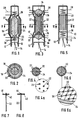
- Fig. 1 eine erste Ausführungsform der Erfindung im Längsschnitt,
- Fig. 2 den Schnitt nach Linie II-II 'gemäss Fig. 1,
- Fig. 3 eine zweite Ausführungsform der Erfindung,
- Fig. 4, 4a den Schnitt nach Linie IV-IV gemäss Fig. 3, wobei Fig. 4a eine Detailvergrösserung darstellt,
- Fig. 5 eine dritte Ausführungsform der Erfindung,
- Fig. 6, 6a den Schnitt nach Linie VI-VI gemäss Fig. 5, wobei Fig. 6a eine Detailvergrösserung darstellt, und
- Fig. 7, 8 Ausführungsbeispiele für die Befestigung der stabartigen Elemente.
- Ein in einem als Schwingungsraum dienenden Zylinder 10 (Fig. 1) auf- und abbewegter Kolben 12 ist über eine Kolbenstange 14 mit einem nicht dargestellten Kurbeltrieb verbunden. Der mittlere Teil des Zylinders weist eine Ausbuchtung 16 mit einem Strömungskörper 18 auf. Im Ringraum 20 sind stabartige Elemente 22 vorgesehen, welche direkt in der Behälterwand 24 z. B. durch Schweissen befestigt sind. Der Strömungskörper 18 ist mittels Sprossen 26 an der Behälterwand 24 abgestützt. Im oberen Teil des Zylinders ist eine Wärmequelle 28 und im unteren Teil eine Wärmesenke 30 vorgesehen. Beim Betrieb werden thermoakustische Schwingungen im Zylinder 10 angefacht, wobei der Kolben 12 in eine oszillierende Bewegung versetzt wird.
- Beim Ausführungsbeispiel nach Fig. 3 weist der Zylinder 10 eine Einschnürung 32 auf. Zur Befestigung der stabartigen Elemente 22 dienen in diesem Falle zwei Haltkörper 34, 36, welche in Ausbuchtungen 17 abgestützt sind. Die konvex gekrümmte Oberfläche der stabartigen Elemente 22 ist in Fig. 4a mit 23 bezeichnet. Der Betrieb entspricht dem Beispiel nach Fig. 1.
- Beim Ausführungsbeispiel nach Fig. 5 sind die stabartigen Elemente 22 unten an einem netzartigen Boden 38 abgestützt und oben an einem Lochboden 40 nach Fig. 7 befestigt. Die stabartigen Elemente weisen an beiden Enden Erweiterungen 42 auf. Nach Fig. 8 können auch nietkopfartige Erweiterungen 44 vorgesehen sein.
Claims (8)
Applications Claiming Priority (2)
| Application Number | Priority Date | Filing Date | Title |
|---|---|---|---|
| CH269/85 | 1985-01-22 | ||
| CH269/85A CH667517A5 (de) | 1985-01-22 | 1985-01-22 | Thermoakustische vorrichtung. |
Publications (2)
| Publication Number | Publication Date |
|---|---|
| EP0191179A1 EP0191179A1 (de) | 1986-08-20 |
| EP0191179B1 true EP0191179B1 (de) | 1989-04-26 |
Family
ID=4183153
Family Applications (1)
| Application Number | Title | Priority Date | Filing Date |
|---|---|---|---|
| EP85115760A Expired EP0191179B1 (de) | 1985-01-22 | 1985-12-11 | Thermoakustische Vorrichtung |
Country Status (4)
| Country | Link |
|---|---|
| US (1) | US4625517A (de) |
| EP (1) | EP0191179B1 (de) |
| CH (1) | CH667517A5 (de) |
| DE (1) | DE3569818D1 (de) |
Families Citing this family (22)
| Publication number | Priority date | Publication date | Assignee | Title |
|---|---|---|---|---|
| GB8626562D0 (en) * | 1986-11-06 | 1986-12-10 | Wells A A | Gas resonance device |
| US5303555A (en) * | 1992-10-29 | 1994-04-19 | International Business Machines Corp. | Electronics package with improved thermal management by thermoacoustic heat pumping |
| US5349813A (en) * | 1992-11-09 | 1994-09-27 | Foster Wheeler Energy Corporation | Vibration of systems comprised of hot and cold components |
| US5412950A (en) * | 1993-07-27 | 1995-05-09 | Hu; Zhimin | Energy recovery system |
| US5456082A (en) * | 1994-06-16 | 1995-10-10 | The Regents Of The University Of California | Pin stack array for thermoacoustic energy conversion |
| US5901556A (en) * | 1997-11-26 | 1999-05-11 | The United States Of America As Represented By The Secretary Of The Navy | High-efficiency heat-driven acoustic cooling engine with no moving parts |
| US6089026A (en) * | 1999-03-26 | 2000-07-18 | Hu; Zhimin | Gaseous wave refrigeration device with flow regulator |
| CA2468136C (en) * | 2001-11-26 | 2011-02-22 | Shell Canada Limited | Thermoacoustic electric power generation |
| US6792764B2 (en) * | 2002-04-10 | 2004-09-21 | The Penn State Research Foundation | Compliant enclosure for thermoacoustic device |
| US6755027B2 (en) * | 2002-04-10 | 2004-06-29 | The Penn State Research Foundation | Cylindrical spring with integral dynamic gas seal |
| US6725670B2 (en) * | 2002-04-10 | 2004-04-27 | The Penn State Research Foundation | Thermoacoustic device |
| WO2004088218A1 (en) | 2003-03-25 | 2004-10-14 | Utah State University | Thermoacoustic cooling device |
| DE102008017998B4 (de) * | 2008-04-09 | 2010-07-01 | Siemens Aktiengesellschaft | Verfahren und Vorrichtung zur Erhöhung der Energieeffizienz eines Kraftwerks |
| DE102008018000B4 (de) * | 2008-04-09 | 2010-04-01 | Siemens Aktiengesellschaft | Verfahren und Vorrichtung zur CO2-Verflüssigung |
| JP2011099599A (ja) * | 2009-11-05 | 2011-05-19 | Aisin Seiki Co Ltd | 熱輸送管 |
| US9646723B2 (en) * | 2012-08-16 | 2017-05-09 | The Penn State Research Foundation | Thermoacoustic enhancements for nuclear fuel rods and other high temperature applications |
| CN103485931A (zh) * | 2013-09-21 | 2014-01-01 | 冯智勇 | 一种热声驱动的斯特林发动机 |
| CN103670977B (zh) * | 2013-12-11 | 2015-12-02 | 中国科学院理化技术研究所 | 一种利用液氧燃烧的双作用热声发电系统 |
| WO2020045675A1 (ja) * | 2018-08-31 | 2020-03-05 | 京セラ株式会社 | 熱音響装置 |
| WO2021152798A1 (ja) * | 2020-01-30 | 2021-08-05 | 京セラ株式会社 | 熱音響装置 |
| WO2021084868A1 (ja) * | 2019-11-01 | 2021-05-06 | 京セラ株式会社 | 熱音響装置 |
| EP4581273A1 (de) * | 2022-08-30 | 2025-07-09 | Technion Research & Development Foundation Limited | Durch bestrahlung eines absorbierenden mediums oder schwingende erwärmung angetriebener thermoakustischer motor |
Family Cites Families (16)
| Publication number | Priority date | Publication date | Assignee | Title |
|---|---|---|---|---|
| FR955736A (de) * | 1950-01-19 | |||
| US1548158A (en) * | 1923-06-13 | 1925-08-04 | Thomas E Murray | Heat exchanger |
| DE804147C (de) * | 1944-11-03 | 1951-04-16 | Philips Nv | Aus einem oder mehreren Drahtstuecken bestehende Regeneratorfuellmasse |
| CH284894A (de) * | 1948-12-24 | 1952-08-15 | Philips Nv | Gasmaschine. |
| US2836033A (en) * | 1953-07-15 | 1958-05-27 | Bell Telephone Labor Inc | Heat-controlled acoustic wave system |
| DE1005673B (de) * | 1955-06-11 | 1957-04-04 | Rudolf Hingst Dipl Ing | Regenerativ-Waermeaustauscher aus Reihen von Eisenstaeben zur Anordnung in einem abwechselnd von den aufzuheizenden und den waermeabgebenden Mitteln durchstroemten Kanal |
| US3339635A (en) * | 1965-10-22 | 1967-09-05 | Clarence W Brandon | Method and apparatus for forming and/or augmenting an energy wave |
| US3548589A (en) * | 1968-01-19 | 1970-12-22 | Atomic Energy Authority Uk | Heat engines |
| GB1361979A (en) * | 1971-12-09 | 1974-07-30 | Atomic Energy Authority Uk | Stirling cycle heat engines |
| US4114380A (en) * | 1977-03-03 | 1978-09-19 | Peter Hutson Ceperley | Traveling wave heat engine |
| US4296147A (en) * | 1979-05-21 | 1981-10-20 | William Nicholas Lawless | Thallous halide materials for use in cryogenic applications |
| US4355517A (en) * | 1980-11-04 | 1982-10-26 | Ceperley Peter H | Resonant travelling wave heat engine |
| FR2536788A2 (fr) * | 1981-08-14 | 1984-06-01 | Us Energy | Moteur thermique intrinsequement irreversible |
| US4489553A (en) * | 1981-08-14 | 1984-12-25 | The United States Of America As Represented By The United States Department Of Energy | Intrinsically irreversible heat engine |
| US4398398A (en) * | 1981-08-14 | 1983-08-16 | Wheatley John C | Acoustical heat pumping engine |
| CH660779A5 (de) * | 1983-06-20 | 1987-06-15 | Sulzer Ag | Kaeltemaschine oder waermepumpe mit thermoakustischen antriebs- und arbeitsteilen. |
-
1985
- 1985-01-22 CH CH269/85A patent/CH667517A5/de not_active IP Right Cessation
- 1985-12-11 DE DE8585115760T patent/DE3569818D1/de not_active Expired
- 1985-12-11 EP EP85115760A patent/EP0191179B1/de not_active Expired
-
1986
- 1986-01-10 US US06/818,089 patent/US4625517A/en not_active Expired - Fee Related
Also Published As
| Publication number | Publication date |
|---|---|
| CH667517A5 (de) | 1988-10-14 |
| US4625517A (en) | 1986-12-02 |
| EP0191179A1 (de) | 1986-08-20 |
| DE3569818D1 (en) | 1989-06-01 |
Similar Documents
| Publication | Publication Date | Title |
|---|---|---|
| EP0191179B1 (de) | Thermoakustische Vorrichtung | |
| DE2523289C2 (de) | Schalldämpfer | |
| DE970926C (de) | Vorrichtung zum Mischen, Ruehren usw. von Fluessigkeiten | |
| DE60307246T2 (de) | Dämpfer mit abstimmbarer masse mit translationsachsendämpfung | |
| DE2401815A1 (de) | Schwingungsdaempfende halterung | |
| DE2617369B2 (de) | Gekapselter Motorverdichter für Kältemaschinen | |
| DE1204540B (de) | Fahrzeugabfederung, bei der die abzufedernde Last gleichzeitig von zwei Arten von elastischen Abfederungsgliedern getragen wird | |
| DE2407029A1 (de) | Lineare ausgeglichene freikolbenmaschine | |
| DE69925997T2 (de) | Zweibeiniger körper | |
| DE2163798A1 (de) | Resonanzabsorber fuer periodische und aperiodische schwingungen | |
| DE3925788A1 (de) | Haltevorrichtung fuer eine ultraschallvibrationseinrichtung | |
| DE60025162T2 (de) | Monolithische struktur eines schwingungs-gyroskops | |
| DE3610674C2 (de) | ||
| DE3305051A1 (de) | Waermeaustauscher mit verbesserter rohrreinigungselementkorb-befestigung | |
| EP0102490A1 (de) | Dichtemesser für Gase | |
| DE4418287A1 (de) | Vorrichtung zum Mischen zweier Fluide | |
| DE2931002C2 (de) | Halterung für Feuerlöscher | |
| DE841649C (de) | Vorrichtung zum Erzeugen von Schwingungen an technischen Gebilden | |
| DE910544C (de) | Waermeaustauscher | |
| DE1955885A1 (de) | Staubsammelvorrichtung | |
| DE279336C (de) | ||
| DE9414064U1 (de) | Höhen- und längenverstellbares Trägerelement für Hängematten | |
| DE725687C (de) | Stossdaempferanordnung, insbesondere fuer Schwerlastkraftfahrzeuge | |
| DE4028913A1 (de) | Wasserschallwandler fuer tiefe frequenzen | |
| DE2620640A1 (de) | Fuehl- und einstellvorrichtung fuer eine regelanordnung mit mehreren thermostatisch betaetigten ventilen |
Legal Events
| Date | Code | Title | Description |
|---|---|---|---|
| PUAI | Public reference made under article 153(3) epc to a published international application that has entered the european phase |
Free format text: ORIGINAL CODE: 0009012 |
|
| AK | Designated contracting states |
Kind code of ref document: A1 Designated state(s): DE FR IT NL SE |
|
| 17P | Request for examination filed |
Effective date: 19870131 |
|
| 17Q | First examination report despatched |
Effective date: 19871012 |
|
| GRAA | (expected) grant |
Free format text: ORIGINAL CODE: 0009210 |
|
| ITF | It: translation for a ep patent filed | ||
| AK | Designated contracting states |
Kind code of ref document: B1 Designated state(s): DE FR IT NL SE |
|
| REF | Corresponds to: |
Ref document number: 3569818 Country of ref document: DE Date of ref document: 19890601 |
|
| ET | Fr: translation filed | ||
| PLBE | No opposition filed within time limit |
Free format text: ORIGINAL CODE: 0009261 |
|
| STAA | Information on the status of an ep patent application or granted ep patent |
Free format text: STATUS: NO OPPOSITION FILED WITHIN TIME LIMIT |
|
| 26N | No opposition filed | ||
| ITTA | It: last paid annual fee | ||
| PGFP | Annual fee paid to national office [announced via postgrant information from national office to epo] |
Ref country code: SE Payment date: 19911030 Year of fee payment: 7 |
|
| PGFP | Annual fee paid to national office [announced via postgrant information from national office to epo] |
Ref country code: FR Payment date: 19911209 Year of fee payment: 7 |
|
| PGFP | Annual fee paid to national office [announced via postgrant information from national office to epo] |
Ref country code: NL Payment date: 19911231 Year of fee payment: 7 |
|
| PGFP | Annual fee paid to national office [announced via postgrant information from national office to epo] |
Ref country code: DE Payment date: 19920131 Year of fee payment: 7 |
|
| PG25 | Lapsed in a contracting state [announced via postgrant information from national office to epo] |
Ref country code: SE Effective date: 19921212 |
|
| PG25 | Lapsed in a contracting state [announced via postgrant information from national office to epo] |
Ref country code: NL Effective date: 19930701 |
|
| NLV4 | Nl: lapsed or anulled due to non-payment of the annual fee | ||
| PG25 | Lapsed in a contracting state [announced via postgrant information from national office to epo] |
Ref country code: FR Effective date: 19930831 |
|
| PG25 | Lapsed in a contracting state [announced via postgrant information from national office to epo] |
Ref country code: DE Effective date: 19930901 |
|
| REG | Reference to a national code |
Ref country code: FR Ref legal event code: ST |
|
| EUG | Se: european patent has lapsed |
Ref document number: 85115760.2 Effective date: 19930709 |