EP0189552B1 - Pulsateur pour machines à traire - Google Patents
Pulsateur pour machines à traire Download PDFInfo
- Publication number
- EP0189552B1 EP0189552B1 EP85115184A EP85115184A EP0189552B1 EP 0189552 B1 EP0189552 B1 EP 0189552B1 EP 85115184 A EP85115184 A EP 85115184A EP 85115184 A EP85115184 A EP 85115184A EP 0189552 B1 EP0189552 B1 EP 0189552B1
- Authority
- EP
- European Patent Office
- Prior art keywords
- control
- disk
- chambers
- fork
- chamber
- Prior art date
- Legal status (The legal status is an assumption and is not a legal conclusion. Google has not performed a legal analysis and makes no representation as to the accuracy of the status listed.)
- Expired - Lifetime
Links
- 238000013016 damping Methods 0.000 claims abstract description 12
- 230000010349 pulsation Effects 0.000 claims abstract 2
- 238000000638 solvent extraction Methods 0.000 claims 1
- 230000000638 stimulation Effects 0.000 abstract description 14
- 230000005540 biological transmission Effects 0.000 abstract description 5
- 239000012528 membrane Substances 0.000 description 10
- 238000000034 method Methods 0.000 description 3
- 239000008267 milk Substances 0.000 description 1
- 210000004080 milk Anatomy 0.000 description 1
- 235000013336 milk Nutrition 0.000 description 1
Images


Classifications
-
- A—HUMAN NECESSITIES
- A01—AGRICULTURE; FORESTRY; ANIMAL HUSBANDRY; HUNTING; TRAPPING; FISHING
- A01J—MANUFACTURE OF DAIRY PRODUCTS
- A01J5/00—Milking machines or devices
- A01J5/04—Milking machines or devices with pneumatic manipulation of teats
- A01J5/10—Pulsators arranged otherwise than on teat-cups
- A01J5/12—Pulsators arranged otherwise than on teat-cups with membranes
-
- Y—GENERAL TAGGING OF NEW TECHNOLOGICAL DEVELOPMENTS; GENERAL TAGGING OF CROSS-SECTIONAL TECHNOLOGIES SPANNING OVER SEVERAL SECTIONS OF THE IPC; TECHNICAL SUBJECTS COVERED BY FORMER USPC CROSS-REFERENCE ART COLLECTIONS [XRACs] AND DIGESTS
- Y10—TECHNICAL SUBJECTS COVERED BY FORMER USPC
- Y10T—TECHNICAL SUBJECTS COVERED BY FORMER US CLASSIFICATION
- Y10T137/00—Fluid handling
- Y10T137/2496—Self-proportioning or correlating systems
- Y10T137/2544—Supply and exhaust type
- Y10T137/2546—Vacuum or suction pulsator type [e.g., milking machine]
-
- Y—GENERAL TAGGING OF NEW TECHNOLOGICAL DEVELOPMENTS; GENERAL TAGGING OF CROSS-SECTIONAL TECHNOLOGIES SPANNING OVER SEVERAL SECTIONS OF THE IPC; TECHNICAL SUBJECTS COVERED BY FORMER USPC CROSS-REFERENCE ART COLLECTIONS [XRACs] AND DIGESTS
- Y10—TECHNICAL SUBJECTS COVERED BY FORMER USPC
- Y10T—TECHNICAL SUBJECTS COVERED BY FORMER US CLASSIFICATION
- Y10T137/00—Fluid handling
- Y10T137/8593—Systems
- Y10T137/86389—Programmer or timer
- Y10T137/86405—Repeating cycle
- Y10T137/86421—Variable
Definitions
- the invention relates to a pulsator for milking machines with two membranes connected by a rod, each of which divides a pressure can into a working space and a damping space, of which the damping spaces are connected to one another via a connecting channel provided with the throttle point, while the working spaces alternately a vacuum source or the atmosphere can be connected, and with a reversing device connected to the rod for alternately connecting lines leading to the pulse spaces of teat cups with the atmosphere or a main line leading to the vacuum source and provided with a throttle point, the throttle points in the connecting channel and are bypassed in the main line by bypass lines which are provided with shut-off elements which can be actuated by means of negative pressure via control channels.
- Such a pulsator is known, for example, from EP-A 0032752 and is used during a stimulation phase preceding the actual milking process to apply a significantly increased number of pulsator cycles to the pulse chambers of the teat cups while simultaneously reducing the pressure differences that become effective in the pulse chambers.
- the desired duration of the stimulation phase is set on a timer, after which the shut-off elements arranged in the control lines are actuated.
- Squeezing devices are used as shut-off devices, which compress and thus close the control channels, which are at least partially designed as elastic hoses. Such hoses that are mechanically stressed, however, can be easily damaged and then lead to failure of the pulsator.
- the invention has for its object to improve the known pulsator so that there is no need for susceptible hoses and time clocks and the duration of the stimulation phase can be set independently of time.
- control channels are each connected to one of the control chambers of a control disc, of which one control chamber is permanently connected to the negative pressure source and the other control chambers are under atmospheric pressure, the control disc via a transmission which is different from the reciprocating rod is driven, is rotatable and thereby the control channels are alternately connected to the negative pressure control chamber or one of the control chambers under atmospheric pressure.
- the length of the stimulation phase is determined by the number of pulsator cycles and the associated changes in direction of the rod connected to the membranes, as well as by the translation of the gear driven by the rod and the design of the control disk rotatable by the gear.
- the transmission is provided with a drive fork which can be pivoted about a fulcrum, which is connected to a driver fastened to the rod and at its fulcrum via a flat toothing which is only positive in one direction of rotation and is connected to a drive pulley which is connected via a at its eccentrically arranged driver is connected to a control fork, which is connected at its pivot point to the control disk via a flat toothing that is only positive in one direction of rotation, the toothing of the control disk being interrupted by a tooth gap at least at one point and the control fork at least has a tooth.
- the oscillating movement of the drive fork is transmitted via the toothing as a rotary movement only in one direction to the drive pulley, which moves one tooth pitch with each complete pulsator cycle.
- a full rotation of the drive pulley causes the control pulley to rotate by one tooth pitch in the same way.
- the control disc is no longer moved despite the continuous oscillating movement of the control fork.
- a rotation of the drive disk by frictional forces in the toothing when the control fork swings back against the desired direction of rotation can be prevented, for example, by the drive disk being provided with an annular channel on its non-toothed side and being arranged with this side on a flat surface provided in the pulsator and in the Flat surface is provided a channel that is connected to the vacuum source and opens into the ring channel. Due to the negative pressure, the drive pulley is pressed against the flat surface and the friction generated thereby prevents the drive pulley from turning back.
- connection of the control channels with the control chambers of the control disk can be established simply and effectively in that the control chambers are provided on the non-toothed side of the control disk, the control disk is arranged with one side on the plane surface in which the control channels and a channel leading to the vacuum source are arranged so that a control chamber is permanently connected to the vacuum source and the control channels are connected to this control chamber or one of the other control chambers, depending on the position of the control disk.
- the connection is free of play, low wear and self-adjusting and at the same time prevents the control disc from turning back due to the oscillating control fork due to the negative pressure present.
- Secure driving of the drive disk and control disk via the toothing in the desired direction of rotation can be achieved in that the drive fork and the control fork are each pressed against the drive disk or control disk by springs.
- the control disk Since the tooth of the control fork is in the tooth gap of the control disk after the milking process has ended, the control disk must be moved one tooth pitch in the direction of rotation in order to carry out renewed stimulation.
- a starting lever is provided on the control disc, which is connected to the control disc via a toothing that is only positive in one direction of rotation, the starting lever being held in a starting position by a resilient element and a stop limiting the actuation path of the starting lever .
- Fig. 1 denotes the rod which is connected to the two membranes 2, 3 in the pressure sockets 4, 5.
- the pressure cells 4, 5 are divided by the membranes 2, 3 into a work space 6, 7 and a damping space 8, 9 each.
- the work rooms 6, 7 are alternately pressurized by a control device, not shown.
- the damping spaces are connected to one another via a connecting duct 11 provided with a throttle point 10.
- a change-over device 12 is provided on the rod 1, which connects the lines 13, 14 leading to the pulse spaces of milking cups with the atmosphere or a main line 16 leading to the vacuum source and provided with a throttle point 15.
- Both the throttle point 10 and the throttle point 15 are bridged by bypass lines 17, 18, in which shut-off devices 19, 20 are provided, which can be actuated by means of negative pressure via control channels 21, 22.
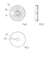
- the control channels 21, 22 are each connected to one of the control chambers 23, 24, 25 of the control disk 26, of which the control chamber 23 is permanently connected to the vacuum source via a channel 27, while the other control chambers 24, 25 are connected via channels 28, 29 associated with the atmosphere.
- a driver 30 is provided on the rod 1 and is connected to the drive fork 31 of a transmission 32.
- the drive fork 31 is connected at its pivot point 33 to the drive disk 35 via a toothing 34 that can be seen in FIGS. 2 to 5.
- a driver 36 arranged eccentrically on the drive disk 35 is connected to the control fork 37, which is connected at its pivot point 38 to the control disk 26 via a toothing 39.
- the control fork 37 is surrounded at its pivot point 38 by a start lever 40 which is connected to the control disk 26 via the toothing 41.
- the start lever 40 is held in a starting position by a resilient element 42 and its actuation path is limited by a stop 43.
- the toothing 39 of the control disk 26 is interrupted at one point by a tooth gap 44 and the control fork 37 is provided with only one tooth 45.
- the drive disc 35 is provided on its toothless side with an annular channel 46 which is permanently connected to the vacuum source via a channel 48 provided in the flat surface 47.
- the drive fork 31 and the control fork 37 are pressed against the toothings 34, 39 by springs 49, 50.
- control rooms 23, 24, 25 of the control disk 26, relative to the control channels 21, 22, is shown in FIG. 6 in the stimulation phase and FIG. 7 in the milking phase.
- the tooth 45 of the control fork 37 is in the tooth gap 44 of the control disk 26, which is now not rotated further despite the oscillating movement of the control fork 37.
- the channel 21 is connected to the control chamber 24 and the channel 22 to the control chamber 23.
- the shut-off device 19 in the bypass line 17 is thereby ventilated and closes the bypass line 17 by means of a spring-loaded membrane 51, as a result of which the damping chambers 8, 9 are connected to one another only via the throttle point 10, which represents a high resistance.
- the pulsator now works with a cycle number that is usual for the milking process.
- the membrane 52 in the shut-off device 20 in the bypass line 18 is under negative pressure on both sides and the shut-off device 20 is thereby opened.
- the start lever 40 To trigger the stimulation phase, the start lever 40 must be moved as far as the stop 43, as a result of which the control disk 26 is moved one tooth pitch in its direction of rotation and the tooth 45 of the control fork with the toothing 39 comes into engagement.
- the control disk 26 now has the position shown in FIG. 6, as a result of which vacuum is applied to the diaphragm 51 of the shut-off element 19 via control channel 21 and thereby opens, while via control channel 22 the diaphragm 52 of the shut-off element 20 is ventilated on one side and thereby closes.
- the two damping chambers 8, 9 are connected to one another over a large cross-section, which leads to a multiplication of the number of cycles, while the supply of the lines 13, 14 with negative pressure is only via the throttle point 15 takes place so that only a reduced vacuum can build up in the pulse chambers of the teat cup.
- the drive fork 31 With each reciprocating movement of the rod 1, the drive fork 31 is also deflected about the pivot point 33 in both directions of rotation via the driver 30.
- Via the toothing 34 which is form-fitting only in one direction of rotation, it transmits its movement only in one direction of rotation, while it is offset in the opposite direction by one tooth pitch with respect to the drive disk 35.
- the control fork With a full rotation of the drive disk 35, the control fork also carries out a full oscillating movement via the driver 36 and transmits this in the same way as the drive fork 31 to the control disk 26.
- the rotary movement of the control disk 26 is ended as soon as it has completed a full rotation and the tooth 45 of the control fork 37 is again in the tooth gap 44 of the control disk 26 and thus again in the starting position described above.
- the duration of the stimulation phase depends on the number of pulsator cycles during the stimulation phase and on the gear ratio selected.
- the pulsator cycle number can be determined by the choice of the cross section of the bypass line 17. If the pulsator cycle number during the stimulation phase is, for example, 300 min-1 and the gear ratio is 1: 300, the stimulation phase lasts 60 seconds.
Landscapes
- Life Sciences & Earth Sciences (AREA)
- Animal Husbandry (AREA)
- Environmental Sciences (AREA)
- External Artificial Organs (AREA)
- Soil Working Implements (AREA)
- Dairy Products (AREA)
- Transmission Devices (AREA)
- Percussion Or Vibration Massage (AREA)
- Actuator (AREA)
- Reciprocating Pumps (AREA)
- Dynamo-Electric Clutches, Dynamo-Electric Brakes (AREA)
- Massaging Devices (AREA)
- Push-Button Switches (AREA)
- Electrophonic Musical Instruments (AREA)
- Multiple-Way Valves (AREA)
- Medicines Containing Plant Substances (AREA)
- Saccharide Compounds (AREA)
- Disintegrating Or Milling (AREA)
Claims (6)
Priority Applications (1)
| Application Number | Priority Date | Filing Date | Title |
|---|---|---|---|
| AT85115184T ATE49849T1 (de) | 1985-01-31 | 1985-11-29 | Pulsator fuer melkmaschinen. |
Applications Claiming Priority (2)
| Application Number | Priority Date | Filing Date | Title |
|---|---|---|---|
| DE3503245A DE3503245C1 (de) | 1985-01-31 | 1985-01-31 | Pulsator fuer Melkmaschinen |
| DE3503245 | 1985-01-31 |
Publications (3)
| Publication Number | Publication Date |
|---|---|
| EP0189552A2 EP0189552A2 (fr) | 1986-08-06 |
| EP0189552A3 EP0189552A3 (en) | 1988-01-20 |
| EP0189552B1 true EP0189552B1 (fr) | 1990-01-31 |
Family
ID=6261287
Family Applications (1)
| Application Number | Title | Priority Date | Filing Date |
|---|---|---|---|
| EP85115184A Expired - Lifetime EP0189552B1 (fr) | 1985-01-31 | 1985-11-29 | Pulsateur pour machines à traire |
Country Status (15)
| Country | Link |
|---|---|
| US (1) | US4643132A (fr) |
| EP (1) | EP0189552B1 (fr) |
| JP (1) | JPS62122539A (fr) |
| AT (1) | ATE49849T1 (fr) |
| AU (1) | AU580125B2 (fr) |
| BR (1) | BR8600343A (fr) |
| CA (1) | CA1248903A (fr) |
| DD (1) | DD241543A5 (fr) |
| DE (1) | DE3503245C1 (fr) |
| DK (1) | DK167087B1 (fr) |
| ES (1) | ES8706014A1 (fr) |
| FI (1) | FI79776C (fr) |
| IL (1) | IL77592A (fr) |
| NZ (1) | NZ214976A (fr) |
| RU (1) | RU1793857C (fr) |
Families Citing this family (3)
| Publication number | Priority date | Publication date | Assignee | Title |
|---|---|---|---|---|
| SE9702029D0 (sv) * | 1997-05-29 | 1997-05-29 | Alfa Laval Agri Ab | Pulsator |
| DE102005018335A1 (de) | 2005-04-20 | 2006-11-02 | Lactocorder Ag | Vorrichtung zur Stimulation eines Euters bei einem Melkvorgang |
| RU2701323C1 (ru) * | 2018-11-14 | 2019-09-25 | Евгений Дмитриевич Свияженинов | Мультипликативный золотниковый пульсатор аппарата попеременного доения |
Family Cites Families (8)
| Publication number | Priority date | Publication date | Assignee | Title |
|---|---|---|---|---|
| US2822823A (en) * | 1954-08-04 | 1958-02-11 | Mcneil Machine & Eng Co | Rotary disk valve with ratchet operating means |
| DE1750003A1 (de) * | 1968-03-20 | 1971-01-07 | Bizerba Werke Kraut Kg Wilh | Steuerschieber |
| IT1104875B (it) * | 1978-09-20 | 1985-10-28 | Ligabue Interpuls Snc | Apparecchio pulsatore per impianti di mungitura |
| NL179781C (fr) * | 1979-04-11 | Westfalia Separator Ag | ||
| SU827861A2 (ru) * | 1979-06-07 | 1981-05-07 | Plotko Mikhail A | Гидропривод малых подач |
| DE7922032U1 (de) * | 1979-08-01 | 1980-12-04 | Happel, Fritz, 8951 Baisweil | Pulsator für Melkmaschinen |
| DK152321C (da) * | 1980-01-21 | 1988-07-11 | Hoefelmayr Bio Melktech | Fremgangsmaade og apparat til maskinel udmalkning |
| US4298025A (en) * | 1980-05-05 | 1981-11-03 | Kinetico, Inc. | Control valve for water softeners |
-
1985
- 1985-01-31 DE DE3503245A patent/DE3503245C1/de not_active Expired
- 1985-11-29 AT AT85115184T patent/ATE49849T1/de not_active IP Right Cessation
- 1985-11-29 EP EP85115184A patent/EP0189552B1/fr not_active Expired - Lifetime
-
1986
- 1986-01-02 AU AU51826/86A patent/AU580125B2/en not_active Ceased
- 1986-01-06 DK DK004886A patent/DK167087B1/da active
- 1986-01-14 IL IL77592A patent/IL77592A/xx unknown
- 1986-01-17 US US06/820,755 patent/US4643132A/en not_active Expired - Lifetime
- 1986-01-21 CA CA000500033A patent/CA1248903A/fr not_active Expired
- 1986-01-22 RU SU864011816A patent/RU1793857C/ru active
- 1986-01-28 FI FI860408A patent/FI79776C/fi not_active IP Right Cessation
- 1986-01-29 DD DD86286587A patent/DD241543A5/de not_active IP Right Cessation
- 1986-01-29 NZ NZ214976A patent/NZ214976A/en unknown
- 1986-01-29 BR BR8600343A patent/BR8600343A/pt not_active IP Right Cessation
- 1986-01-30 JP JP61016981A patent/JPS62122539A/ja active Granted
- 1986-01-31 ES ES551533A patent/ES8706014A1/es not_active Expired
Also Published As
| Publication number | Publication date |
|---|---|
| DE3503245C1 (de) | 1986-02-13 |
| FI79776B (fi) | 1989-11-30 |
| DK167087B1 (da) | 1993-08-30 |
| DK4886D0 (da) | 1986-01-06 |
| EP0189552A3 (en) | 1988-01-20 |
| DD241543A5 (de) | 1986-12-17 |
| US4643132A (en) | 1987-02-17 |
| AU580125B2 (en) | 1989-01-05 |
| BR8600343A (pt) | 1986-10-14 |
| FI860408A0 (fi) | 1986-01-28 |
| ES8706014A1 (es) | 1987-05-16 |
| ES551533A0 (es) | 1987-05-16 |
| FI860408A7 (fi) | 1986-08-01 |
| CA1248903A (fr) | 1989-01-17 |
| JPS62122539A (ja) | 1987-06-03 |
| IL77592A (en) | 1990-04-29 |
| AU5182686A (en) | 1986-08-07 |
| ATE49849T1 (de) | 1990-02-15 |
| NZ214976A (en) | 1988-02-29 |
| DK4886A (da) | 1986-08-01 |
| JPS639809B2 (fr) | 1988-03-02 |
| FI79776C (fi) | 1990-03-12 |
| EP0189552A2 (fr) | 1986-08-06 |
| RU1793857C (ru) | 1993-02-07 |
Similar Documents
| Publication | Publication Date | Title |
|---|---|---|
| DE2102441B2 (de) | Zeitglied für binäre pneumatische Signale | |
| EP0189552B1 (fr) | Pulsateur pour machines à traire | |
| DE2140972C3 (de) | Indirekt steuerbares Servoventil | |
| DE1917368B2 (de) | Mit Druckluft arbeitende Hilfs kraft Schaltvorrichtung fur synchronisierte Wechselgetriebe von Kraftfahrzeugen | |
| DE2146934B2 (de) | Elektromechanisches Hubgerät | |
| DE2242086A1 (de) | Eine vorrichtung fuer einen drucker | |
| DE2753638B2 (de) | Vorrichtung zum Abteilen einer Webkette mit Fadenkreuzen | |
| DE675501C (de) | Druckmittelschaltvorrichtung fuer Zahnraederwechselgetriebe, insbesondere von Kraftfahrzeugen | |
| DE3009418C2 (de) | Einrichtung zur Erzeugung einer periodisch schwellenden Drehbewegung eines Bauteils | |
| DE2631705A1 (de) | Steuervorrichtung fuer ein linear verschiebbares element | |
| DE3340580C2 (fr) | ||
| DE3208226C2 (fr) | ||
| DE2042826B2 (de) | Schrittschaltvorrichtung | |
| DE612518C (de) | Spindelantrieb mit loesbarer Verbindung zwischen Spindel und Handrad fuer Ventile, Schieber o. dgl. | |
| DE2703893C3 (de) | Zeitsteuergerät für pneumatische Signale | |
| DE3639501C2 (fr) | ||
| DE552492C (de) | Kombiniertes Brems- und Kupplungsgetriebe | |
| DE1010794B (de) | Hydraulische Antriebsvorrichtung zur Erzielung gleichzeitiger Bewegungen um zwei senkrecht zueinander stehende Achsen | |
| DE584030C (de) | Steuerung fuer mechanisch angetriebene Spannvorrichtungen an Futterautomaten | |
| DE854898C (de) | Drehschieberventil fuer Druckmittel-Tuerbetaetigungsvorrichtungen, insbesondere fuerKraftfahrzeuge | |
| DE870930C (de) | Werkzeugschlittenantrieb fuer senkrechte Stangenabstechautomaten | |
| DE1472402C3 (de) | Kupplungsvorrichtung für wahlweise mit einer gemeinsamen Bedienungshandhabe verbindbare Einstelleinrichtungen für Abstimm- und Anzeigeeinrichtungen in Rundfunkempfängern für AM- und FM-Empfang | |
| DE509666C (de) | Pulsator fuer Melkmaschinen | |
| AT123522B (de) | Gesteinsbohrmaschine. | |
| DE180193C (fr) |
Legal Events
| Date | Code | Title | Description |
|---|---|---|---|
| PUAI | Public reference made under article 153(3) epc to a published international application that has entered the european phase |
Free format text: ORIGINAL CODE: 0009012 |
|
| 17P | Request for examination filed |
Effective date: 19851212 |
|
| AK | Designated contracting states |
Kind code of ref document: A2 Designated state(s): AT BE CH FR GB IT LI NL SE |
|
| PUAL | Search report despatched |
Free format text: ORIGINAL CODE: 0009013 |
|
| AK | Designated contracting states |
Kind code of ref document: A3 Designated state(s): AT BE CH FR GB IT LI NL SE |
|
| 17Q | First examination report despatched |
Effective date: 19890510 |
|
| GRAA | (expected) grant |
Free format text: ORIGINAL CODE: 0009210 |
|
| AK | Designated contracting states |
Kind code of ref document: B1 Designated state(s): AT BE CH FR GB IT LI NL SE |
|
| REF | Corresponds to: |
Ref document number: 49849 Country of ref document: AT Date of ref document: 19900215 Kind code of ref document: T |
|
| GBT | Gb: translation of ep patent filed (gb section 77(6)(a)/1977) | ||
| ITF | It: translation for a ep patent filed | ||
| ET | Fr: translation filed | ||
| PLBE | No opposition filed within time limit |
Free format text: ORIGINAL CODE: 0009261 |
|
| STAA | Information on the status of an ep patent application or granted ep patent |
Free format text: STATUS: NO OPPOSITION FILED WITHIN TIME LIMIT |
|
| 26N | No opposition filed | ||
| ITTA | It: last paid annual fee | ||
| EAL | Se: european patent in force in sweden |
Ref document number: 85115184.5 |
|
| PGFP | Annual fee paid to national office [announced via postgrant information from national office to epo] |
Ref country code: GB Payment date: 19981026 Year of fee payment: 14 |
|
| PGFP | Annual fee paid to national office [announced via postgrant information from national office to epo] |
Ref country code: AT Payment date: 19981028 Year of fee payment: 14 |
|
| PGFP | Annual fee paid to national office [announced via postgrant information from national office to epo] |
Ref country code: FR Payment date: 19981117 Year of fee payment: 14 |
|
| PGFP | Annual fee paid to national office [announced via postgrant information from national office to epo] |
Ref country code: SE Payment date: 19981120 Year of fee payment: 14 Ref country code: BE Payment date: 19981120 Year of fee payment: 14 |
|
| PGFP | Annual fee paid to national office [announced via postgrant information from national office to epo] |
Ref country code: NL Payment date: 19981126 Year of fee payment: 14 |
|
| PGFP | Annual fee paid to national office [announced via postgrant information from national office to epo] |
Ref country code: CH Payment date: 19981207 Year of fee payment: 14 |
|
| PG25 | Lapsed in a contracting state [announced via postgrant information from national office to epo] |
Ref country code: GB Free format text: LAPSE BECAUSE OF NON-PAYMENT OF DUE FEES Effective date: 19991129 Ref country code: AT Free format text: LAPSE BECAUSE OF NON-PAYMENT OF DUE FEES Effective date: 19991129 |
|
| PG25 | Lapsed in a contracting state [announced via postgrant information from national office to epo] |
Ref country code: SE Free format text: LAPSE BECAUSE OF NON-PAYMENT OF DUE FEES Effective date: 19991130 Ref country code: LI Free format text: LAPSE BECAUSE OF NON-PAYMENT OF DUE FEES Effective date: 19991130 Ref country code: CH Free format text: LAPSE BECAUSE OF NON-PAYMENT OF DUE FEES Effective date: 19991130 Ref country code: BE Free format text: LAPSE BECAUSE OF NON-PAYMENT OF DUE FEES Effective date: 19991130 |
|
| BERE | Be: lapsed |
Owner name: WESTFALIA SEPARATOR A.G. Effective date: 19991130 |
|
| PG25 | Lapsed in a contracting state [announced via postgrant information from national office to epo] |
Ref country code: NL Free format text: LAPSE BECAUSE OF NON-PAYMENT OF DUE FEES Effective date: 20000601 |
|
| REG | Reference to a national code |
Ref country code: CH Ref legal event code: PL |
|
| EUG | Se: european patent has lapsed |
Ref document number: 85115184.5 |
|
| GBPC | Gb: european patent ceased through non-payment of renewal fee |
Effective date: 19991129 |
|
| PG25 | Lapsed in a contracting state [announced via postgrant information from national office to epo] |
Ref country code: FR Free format text: LAPSE BECAUSE OF NON-PAYMENT OF DUE FEES Effective date: 20000731 |
|
| NLV4 | Nl: lapsed or anulled due to non-payment of the annual fee |
Effective date: 20000601 |
|
| REG | Reference to a national code |
Ref country code: FR Ref legal event code: ST |