EP0189290A2 - Vorrichtung zum Positionieren von Substraten verschiedener Grösse von gedruckten Schaltungen - Google Patents
Vorrichtung zum Positionieren von Substraten verschiedener Grösse von gedruckten Schaltungen Download PDFInfo
- Publication number
- EP0189290A2 EP0189290A2 EP86300314A EP86300314A EP0189290A2 EP 0189290 A2 EP0189290 A2 EP 0189290A2 EP 86300314 A EP86300314 A EP 86300314A EP 86300314 A EP86300314 A EP 86300314A EP 0189290 A2 EP0189290 A2 EP 0189290A2
- Authority
- EP
- European Patent Office
- Prior art keywords
- axis
- positioning
- movable
- substrate
- engagement
- Prior art date
- Legal status (The legal status is an assumption and is not a legal conclusion. Google has not performed a legal analysis and makes no representation as to the accuracy of the status listed.)
- Granted
Links
Images


Classifications
-
- H—ELECTRICITY
- H05—ELECTRIC TECHNIQUES NOT OTHERWISE PROVIDED FOR
- H05K—PRINTED CIRCUITS; CASINGS OR CONSTRUCTIONAL DETAILS OF ELECTRIC APPARATUS; MANUFACTURE OF ASSEMBLAGES OF ELECTRICAL COMPONENTS
- H05K13/00—Apparatus or processes specially adapted for manufacturing or adjusting assemblages of electric components
- H05K13/0061—Tools for holding the circuit boards during processing; handling transport of printed circuit boards
-
- Y—GENERAL TAGGING OF NEW TECHNOLOGICAL DEVELOPMENTS; GENERAL TAGGING OF CROSS-SECTIONAL TECHNOLOGIES SPANNING OVER SEVERAL SECTIONS OF THE IPC; TECHNICAL SUBJECTS COVERED BY FORMER USPC CROSS-REFERENCE ART COLLECTIONS [XRACs] AND DIGESTS
- Y10—TECHNICAL SUBJECTS COVERED BY FORMER USPC
- Y10T—TECHNICAL SUBJECTS COVERED BY FORMER US CLASSIFICATION
- Y10T29/00—Metal working
- Y10T29/53—Means to assemble or disassemble
- Y10T29/5313—Means to assemble electrical device
- Y10T29/53174—Means to fasten electrical component to wiring board, base, or substrate
- Y10T29/53183—Multilead component
-
- Y—GENERAL TAGGING OF NEW TECHNOLOGICAL DEVELOPMENTS; GENERAL TAGGING OF CROSS-SECTIONAL TECHNOLOGIES SPANNING OVER SEVERAL SECTIONS OF THE IPC; TECHNICAL SUBJECTS COVERED BY FORMER USPC CROSS-REFERENCE ART COLLECTIONS [XRACs] AND DIGESTS
- Y10—TECHNICAL SUBJECTS COVERED BY FORMER USPC
- Y10T—TECHNICAL SUBJECTS COVERED BY FORMER US CLASSIFICATION
- Y10T29/00—Metal working
- Y10T29/53—Means to assemble or disassemble
- Y10T29/5313—Means to assemble electrical device
- Y10T29/53261—Means to align and advance work part
-
- Y—GENERAL TAGGING OF NEW TECHNOLOGICAL DEVELOPMENTS; GENERAL TAGGING OF CROSS-SECTIONAL TECHNOLOGIES SPANNING OVER SEVERAL SECTIONS OF THE IPC; TECHNICAL SUBJECTS COVERED BY FORMER USPC CROSS-REFERENCE ART COLLECTIONS [XRACs] AND DIGESTS
- Y10—TECHNICAL SUBJECTS COVERED BY FORMER USPC
- Y10T—TECHNICAL SUBJECTS COVERED BY FORMER US CLASSIFICATION
- Y10T74/00—Machine element or mechanism
- Y10T74/20—Control lever and linkage systems
- Y10T74/20207—Multiple controlling elements for single controlled element
Definitions
- the present invention relates generally to an apparatus capable of positioning circuit substrates of different sizes of printed-wiring boards, and more particularly to such a positioning apparatus having a pair of positioning members for positioning the substrates, wherein a distance between the positioning members can be efficiently and accurately changed to suit the specific size of the substrate that is to be positioned.
- An example of a substrate positioning device of the type indicated above comprises a mounting or support member disposed on the NC table and movable along X and Y axes perpendicular to each other, a pair of Y-axis positioning members which are disposed parallel to the X axis and at least one of which is movable toward and away from the other along the Y axis so as to be engageable with opposite parallel sides of the substrate parallel to the X axis to thereby position the substrate in the Y-axis direction, and an X-axis positioning member which is engageable with the substrate to position the substrate in the Y-axis direction.
- This type of positioning device is therefore capable of positioning different sizes of the circuit substrates.
- the distance between the Y-axis positioning members is changed depending upon the sizes of the substrates by the operator, by moving the positionining members toward or away from each other in the Y-axis direction, directly by hand, or by manipulating suitable mechanical means such as a screw-and-nut feed arrangement.
- the above-indicated methods of changing the distance between the positioning members suffer inconveniences. More specifically, where the positioning members are moved directly by hand, considerable efforts and time are required to accurately establish an intended distance between the positioning members suitable for the specific size of a substrate to be positioned. Where a feed screw or other suitable mechanical means is employed, the substrate positioning device is complicated in construction due to additional components of the mechanical means, and expensive particularly when high positioning accuracy is required for establishing the desired spacing between the positioning members.
- a substrate positioning apparatus for positioning circuit substrates of different sizes of printed-wiring boards, comprising an X-Y table having movable means movable along an X axis and a Y axis perpendicular to the X axis, a pair of Y-axis positioning members disposed on the movable means and spaced from each other in the Y-axis direction to position the substrate in the Y-axis direction, and an X-axis positioning member provided on the movable means and engageable with the substrate to position the substrate in the X-axis direction.
- At least one of the Y-axis positioning members is movable along the Y axis so that the Y-axis positioning members are movable toward and away from each other, so that the Y-axis positioning members are engageable with opposite parallel sides of the circuit substrate which are parallel to the X axis, thereby positioning the substrate in the Y-axis direction.
- the instant substrate positioning apparatus further comprises a first engagement member provided on the above-indicated at least one Y-axis positioning member, a second engagement member which is fixed in position in the Y-axis direction, and a first driving device for moving the first and second engagement members relative to each other in a direction perpendicular to the Y axis, and for effecting engagement of the first and second engagement members with each other, to thereby hold the at least one Y-axis positioning member fixed in the Y-axis direction, and permit a change in relative position between the at least one Y-axis positioning member and the movable means in the Y-axis direction through movement of the movable means in the Y-axis direction.
- the distance between the Y-axis positioning members in the Y-axis direction can be changed or adjusted in a process which comprises the steps of: effecting engagement between the first and second engagement members by activating the first driving device, to hold the above-indicated at least one movable Y-axis positioning member fixed in position in the Y-axis direction; then moving the movable means in the Y-axis direction relative to the thus fixed movable Y-axis positioning member, to thereby change a relative position between the movable means and the fixed movable Y-axis positioning member, so that the distance between the pair of Y-axis positioning members is adjusted to suit the size of the substrate; and subsequently releasing the engagement of the first and second engagement members.
- the adjustment of the distance between the Y-axis positioning members in the instant positioning apparatus is carried out by utilizing accurate positioning capability of the movable means which is accurately positioned by the X-Y table provided for positioning the substrate.
- This manner of changing the distance between the Y-axis positioning members permits faster and more accurate positioning of the Y-axis positioning members, than - the conventionally practiced manual positioning by hand or by means of a feed screw arrangement or other mechanical feed system.
- the positioning steps for positioning the Y-axis positioning members in the present apparatus can be automated, without the provision of an expensive additional driving device for positioning the Y-axis positioning member in the Y-axis direction for the purpose of changing the distance between the positioning members.
- the present invention provides a simple and inexpensive arrangement for adjusting the above-indicated distance to meet various sizes of the substrates to be positioned.
- the at least one movable Y-axis positioning member is normally fixed to the movable means.
- suitable means such as frictional clamping means or a positive clamp mechanism may be provided.
- frictional clamping means a frictional force is applied between the movable Y-axis positioning member and the movable means, so that the frictional force does not permit a relative displacement between the movable Y-axis positioning member and the movable means when the movable means is moved in the Y-axis direction during normal positioning operations for positioning the substrate, but permits the relative displacement when the movable means is moved in the Y-axis direction with the movable Y-axis positioning member held fixed through the engagement of the first and second engagement members as previously described.
- the movable Y-axis positioning member is normally positively clamped to the movable means by the clamp mechanism. Therefore, it is necessary to automatically or manually unclamp the movable Y-axis positioning member, before the movable means is moved relative to the movable Y-axis positioning member to change the distance between the Y-axis positioning members.
- the clamp mechanism may be provided on the at least one movable Y-axis positioning member, such that the clamp mechanism is operable between a clamp position in which the movable Y-axis positioning member is fixed relative to the movable means, and an unclamp position in which the movable Y-axis positioning member is unclamped.
- the clamp mechanism is normally placed in the clamp
- the positioning apparatus further comprises an unclamping member which is fixed in position in the Y-axis direction, and a second driving device for moving the unclamping member and the clamp mechanism relative to each other, to cause the clamp mechanism to be brought into the unclamp position by the unclamping member.
- the at least one movable Y-axis positioning member is normally clamped by the clamp mechanism to the movable means.
- the second driving device is activated to move the unclamping member and the clamp mechanism toward each other so that the clamp mechanism is brought into its unclamp position by the unclamping member.
- the at least one movable Y-axis positioning member is fixed in the Y-axis direction due to the first and second engagement members engaging each other.
- the movable means is moved along the Y axis to change the Y-axis position of the at least one movable Y-axis positioning member relative to the movable means, so as to establish a suitable distance between the Y-axis positioning members corresponding to the size of the substrate.
- the first driving device is activated to disengage the first and second engagement members away from ,each other, while the second driving device is activated to place the clamp mechanism in its clamp position.
- the movable Y-axis positioning member and the movable means are movable together along the X and Y axes, with the former clamped to the latter, for normal positioning of the substrate.
- the distance between the Y-axis positioning members can be changed readily and precisely, with a simple and inexpensive arrangement as previously described.
- the movable Y-axis positioning member is firmly clamped to the movable means by the clamp mechanism, whereby the positioning accuracy of the substrate is improved.
- the clamp mechanism is automatically set in its unclamp position by the unclamping member by activating the second driving device, thus permitting a relative displacement of the movable means and the movable Y-axis positioning member for adjusting the distance between the Y-axis positioning members.
- the first driving device is adapted to serve also as the second driving device for bringing the clamp mechanism into its unclamp position. More specifically, the first driving device is designed to move both of the first engagement member and the clamp mechanism, whereby the first and second engagement members engage each other while at the same time the clamp member is set to its unclamp position.
- the positioning apparatus is simplified.
- the second engagement member is adapted to serve also as the unclamping member, rather than a separate member is provided to exclusively serve as the unclamping member. In this case, too, the positioning apparatus is accordingly simplified.
- the X-axis positioning member is movable in the X-axis direction
- the positioning apparatus further comprises a third engagement member provided on the X-axis positioning member, a fourth positioning member which is fixed in position in the X-axis direction, and a third driving device for moving the third and fourth engagement members relative to each other in a direction perpendicular to the X axis, and for effecting engagement of the third and fourth engagement members with each other, to thereby hold the X-axis positioning member fixed in the X-axis direction, and permit a change in relative position between the X-axis positioning member and the movable means in the X-axis direction through a movement of the movable means in the X-axis direction.
- the relative X-axis position of the X-axis positioning member and the movable means can be changed when the movable means is moved along the X axis while the X-axis positioning member is fixed with the third and fourth engagement members in engagement with each other, as well as the relative Y-axis position of the movable Y-axis positioning member and the movable means can be changed when the movable means is moved along the Y axis while the movable Y-axis positioning member is fixed with the first and second engagement members in engagement with each other, as previously described.
- the positioning apparatus is readily and accurately adaptable to not only the X-axis dimension but also the Y-axis dimension of the substrate to be positioned.
- the above embodiment includes the first and second engagement members and the first driving device for changing the distance between the Y-axis positioning members, it is possible that only the third and fourth engagement members and the second driving device for the X-axis positioning member may be provided without the previously described arrangement for changing the Y-axis distance of the Y-axis positioning members.
- the X-axis positioning member may be normally fixed to the movable means by suitable clamp means similar to that used for the movable Y-axis positioning member.
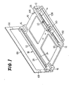
- FIG. 1 a positioning apparatus for positioning a circuit substrate 20 of a printed-wiring board.
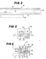
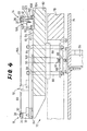
- This substrate positioning apparatus is illustrated in greater detail in a plan view of Fig. 2, a fragmentary rear elevational view of Fig. 3, and a cross sectional view taken along line VI-VI of Fig. 2.
- reference numeral 10 designates a support member in the form of a rectangular support plate which supports a pair of stationary bracket 12, 12 and a pair of movable brackets 16, 16.
- the stationary brackets 12, 12 are fixed to the front left and right corners of the rectangular support plate 10, and supports a stationary guide 14 i
- the movable brackets 16, 16 slidably engage the left and right sides of the support plate 10, and supports a movable guide 18 fixed thereto.
- the movable brackets 16, 16 and the movable guide 18 are movable along a Y axis toward and away from the stationary brackets 12, 12 and the stationary guide 14, whereby the stationary and movable guides 14, 18 are engageable with the opposite front and rear sides of the substrate 20 parallel to an X axis perpendicular to the Y axis.
- the stationary brackets 12, 12 and the stationary guide 14 constitute a stationary Y-axis positioning member while the movable brackets 16, 16 and the movable guide 18 constitute a movable Y-axis positioning member.
- the stationary and movable Y-axis positioning members form a pair of Y-axis positioning members for positioning the substrate 20 in the Y-axis direction, as well as for supporting the substrate 20.
- the stationary and movable guides 14, 18 serve to guide the substrate 20 in the X-axis direction (left and right directions in Fig. 2).
- the stationary guide 14 consists of an elongate guide bar 22 which has a rectangular shape in transverse cross section and extends parallel to the X axis, and a retainer plate 2 6 attached to the top surface of the guide bar 22.
- the movable guide 18 consists of an elongate guide bar 24 and a retainer plate 28 parallel to the guide bar 22.
- the guide bars 22, 24 are attached at their opposite ends to the top surfaces of the corresponding stationary and movable brackets 12, 12, 16, 16, so that the guide bars 22, 24 are located a suitable distance above the top surface of the support plate 10.
- the opposed side surfaces of the guide bars 22, 24 have a pair of opposed cutouts 30, 32 at their upper parts. These cutouts 30, 32 cooperate with the retainer plates 26, 28, respectively., to define a pair of guide grooves which are engageable with the front and rear sides of the substrate 20 parallel to the X axis. Since the stationary and movable guides 14, 18 in this specific embodiment are adapted to permit the substrate 20 to be slidably moved in the X-axis direction, the substate 20 is positioned roughly in the Y-axis direction.
- each of the feed-in and feed-out devices 34, 36 has a pair of conveyer belts 38, 40 on which the substrate 20 is placed for loading and unloading via guide plates 42, 44. More specifically, the substrate 20 which has been conveyed to the feed-in end of the feed-in device 34 is slidably moved on the conveyer belts 38, 40 by a loader (not shown) and pushed in between the previously described stationary and movable guides 14, 18. In the meantime, the substrate 20 supported by the guides 14, 18 is slidably moved between the guides 14, 18 by an unloader (not shown), and pulled onto the conveyer belts 38, 40 of the feed-out device 36.
- the movable brackets 16, 16 are constructed and disposed in exact symmetric relation with each other with respect to the Y axis. For this reason, only the movable bracket 16 provided on the left side of the support plate 10 will be described in detail referring to Figs. 5 and 6, and no detailed description of the right bracket 16 will be given.
- the left movable bracket 16 has in its lower portion a rectangular groove 46, so that the left-hand side end portion of the support plate 10 slidably engages the rectangular groove 46, so as to support the movable bracket 16 along the left side edge of the support plate 10, that is, in the Y-axis direction (perpendicular to the X axis), i.e., in the vertical direction of Fig. 2.
- a mounting surface 48 parallel to the rectangular groove 46, so that the corresponding end of the movable guide 18 is fixed to the mounting surface 48.
- the bottom portion of the movable bracket 16 has a rectangular groove 50 which is formed across the groove 46 and so as to extend along the X axis.
- a clamp lever 52 is received within a portion of the groove 50 above the groove 46.
- the clamp lever 52 is supported pivotally about a pin 54 which extends along the Y axis.
- the clamp lever 52 has an operating portion 56 at its one end, which engages one end of a spring 60.
- This spring 60 is accommodated in a round hole 58 which opens in the mounting surface 48 at its one end and communicates with the rectangular groove 50.
- a friction surface 62 of the clamp lever 52 is normally held in pressed contact with the top surface of the support plate 10, whereby the movable bracket 16 is normally held fixed to the support plate, i.e., fixed in position in the Y-axis direction.
- the biasing force exerted on the operating portion of the clamp lever 52 is boosted at the friction surface 62 with a predetermined advantage according to the principle of a lever, whereby the friction surface. 62 is forced against the support plate 10 with a boosted force.
- the other end of the spring 60 bears on the lower surface of the movable guide 18 fixed to the mounting surface 48.
- an engagement groove 64 which extends in the vertical direction, i.e., along a Z axis perpendicular to the X and Y axes, and which terminates into the groove 50 discussed above.
- This engagement groove 64 is adapted to receive corresponding one of two downward extensions 68, 68 of an engagement member 66 (Fig. 1) which is fixed in the Y-axis direction.
- the thicknesses of the extension 68 and the engagement groove 64 are so determined that the extension 68 fits the groove 64 with only a slight clearance in the Y-axis direction, whereby the movable bracket 16 is fixed in place by the engagement member 66 along the Y axis.
- the extension 68 serves as a second engagement member which is engageable with the engagement groove 64 in order to hold the movable bracket 16 and the movable guide 18 fixed in position, while a portion of'the movable bracket 16 in which the engagement groove 64 is formed serves as a first engagement member which is engageable with the second engagement member 68.
- the other end portion 70 of the clamp lever 52 remote from the operating portion 56 at said one end projects into the engagement groove 64, so that when the extension 68 is inserted into the engagement groove 64, the clamp lever 52 is pivoted by the extension 68 against the biasing force of the biasing spring 60 as shown in broken line in Fig. 6.
- the movable bracket 16 and the movable guide 18 are allowed to move relative to the support plate 10 in the Y-axis direction.
- the clamp lever 52, spring 60, etc. constitute a clamp mechanism for clamping the Y-axis positioning member (16, 18) to the support plate 10
- the extension 68 of the engagement member 66 constitutes an unclamping member for bringing the clamp mechanism into its unclamp position from its clamp position.
- the extension 68 serves not only as the second engagement member, but also as the unclamping member for the clamp mechanism.
- the support plate 10 which supports the stationary and movable brackets 12, 12, 16, 16 and the stationary and movable guides 14, 18, is mounted on an NC (numerically controlled) table 72 which is moved in the X-Y plane.
- the NC table 72 is a well known X-Y table which includes an X-axis slide 78 which is linearly moved along the X axis by a drive motor 76 attached to a base 74, and a Y-axis slide 82 which rests on the X-axis slide 78 and is linearly moved along the Y axis by a drive motor 80.
- the support plate 10 is supported on the Y-axis slide 82 such that the plate 10 is not movable relative to the Y-axis slide 80 in the X- and Y-axis directions, but is movable relative to the Y-axis slide 80 in the vertical direction, that is, along the Z axis normal to the X and Y axes.
- the Y-axis slide 82 has a pair of holes 84, 84 formed in the Z-axis direction through its thickness. Through these holes 86, 86 are inserted a corresponding pair of rods 86, 86 such that the rods 86, 86 are slidable relative to the Y-axis slide 82.
- the support plate 10 is fixed to the top ends of the rods 86, 86 which protrude above the upper surface of the Y-axis slide 82.
- the lower ends of the rods 86, 86 which protrude below the bottom surface of the Y-axis slide 82 are connected to each other by a connecting bar 88, which is held in biased contact with one end of a spring 92 received in a hole 90 formed in the Y-axis slide 82.
- the connecting bar 88 biased downwardly by the spring 92, the support plate 10 is normally held in its lower position in which the bottom surface of the plate 10 abuts on stopper bosses 94 formed on the Y-axis slide 82.
- a cylinder 96 is attached to the base 74.
- a piston rod of the cylinder 96 has an adjusting bolt 98 fixed thereto, so that the adjusting bolt 98 is abutable on the bottom of the connecting bar' 88 to elevate the support plate 10 to its upper position which is spaced a predetermined distance from the upper surface of the Y-axis slide 82.
- the cutouts 30, 32 in the movable and stationary guides 14, 18 are substantially aligned with the upper surfaces of the conveyer belts 38, 40 of the feed-in and feed-out devices 34, 36 previously described. In this condition, the substrate 20 can be transferred from the feed-in device 34, and toward the feed-out device 36.
- the support plate 10 and the substrate 20 supported on the plate 10 are located below the level of the feed-in and feed-out devices 34, 36, so that the support plate 10 and the substrate 20 can be moved along the X and Y axes by and together with the Y-axis slide 82, without an interference with the feed-in and feed-out devices 34, 36.
- the upper opening of the hole 90 in the Y-axis slide 82 is closed by a covering member 100 on which the upper end of the spring 92 bears.
- the X-axis slide 78 is formed with a cutout 102 which extends in the Y-axis direction, so as to permit the lower portions of the rods 86, 86 below the Y-axis slide 82, the connecting bar 88 and other members to be moved with the Y-axis slide 82 in the Y-axis direction.
- the substrate positioning apparatus is provided with movable means which comprises the X-axis slide 78 for moving the substrate 20 along the X axis, the Y-axis slide 82 for moving the substrate 20 along the Y axis, and the support plate 10 for moving the substrate 20 along the Z axis.
- the NC table 72 provides the X- and Y-axis movements of the substrate 20, and the support plate 10 provides the Z-axis movements of the substrate 20.
- a rectangular groove 104 in the X-axis direction In the front portion of the Y-axis slide 82, there is formed a rectangular groove 104 in the X-axis direction. At the right-hand side end portion of this rectangular groove 104 is fixedly disposed a primary positioning member 106. In the remaining portion of the groove 104, there is fixed a guide rail 108 of a U-shape in transverse cross section such that the opening of the U-shape is on the upper side, as clearly shown in Fig. 4. The guide rail 108 slidably supports a secondary positioning member 110 so that the latter is movable in the former in the X-axis direction.
- These primary and secondary positioning members 106, 110 serves to accurately position the substrate 20 along the X and Y axes, after the substrate 20 has been roughly positioned along the Y-axis with the stationary and movable guides 14, 18.
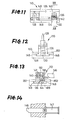
- the primary positioning member 106 comprises a positioning pin 114 which projects upward from a block 112 fixed in the rectangular groove 104, and further comprises a dog plate 118 which is supported pivotally about-a pin 116 fixed to a side surface of the block 112.
- the positioning pin 114 is normally held by a spring 120 in its upper position of Fig. 10. In this upper position, the tip of the positioning pin 114 is lower than the upper surface of the substrate 20 which is supported by the stationary and movable guides 14, 18 while the support plate 10 is in its upper position.
- the positioning pin 114 is inserted through a positioning hole formed in the substrate 20 if the substrate 20 transferred from the feed-in device 34 is correctly positioned.
- the positioning pin 114 is pushed down by the substrate 20 into the block 112 against the biasing action of the spring'120, as indicated in broken line in Fig. 10, when the support plate 10 is lowered to its lower position.
- the positioning pin 114 is formed with a projection 122 at its lower portion.
- This projection 122 extends out of the block 112 through a cutout 123 formed in the block 112, and engages an elongate hole 124 formed in an intermediate portion of the dog plate 118.
- the cutout 123 formed in the block 112 is dimensioned so that the projection 122 is movable in the vertical direction when the pin 114 is moved.
- the secondary positioning member 110 comprises a positioning pin 128 protruding above a block 126 which slidably fits the guide rail 108.
- This positioning pin 128 is normally held by a spring 130 in its upper position.
- the upper position of the positioning pin 128 is determined such that the tip of the positioning pin 128 is lower than the upper surface of the substrate 20 supported by the support plate 10 in its upper position.
- the positioning pin 128 is inserted through another positioning hole formed in the substrate 20, thus cooperating with the positioning pin 114 of the primary positioning member 106 to position the substrate 20 with high precision.
- the positioning pin 128 is pushed down by the substrate 20 into the block 126 against the biasing action of the spring 130.
- a vertical groove 132 In the front portion of the block 126, i.e., on the right side of the block 126 as viewed in Fig. 13, there is formed a vertical groove 132 in which is supported a clamp lever 134 pivotally about a pin 136.
- a hole 140 is formed in the block 126 such that the hole 140 opens in the groove 132.
- One end portion 138 of the clamp lever 134 is held in engagement with one end of a spring 142 the other end of which bears on the bottom of the hole 140. With the above one end portion 138 biased by the spring 142, the other end portion 144 of the clamp lever 134 is normally held in pressed contact with the guide rail 108. In this arrangement, the secondary positioning member 110 is normally clamped to the guide rail 108. As indicated in Fig.
- a cylinder 147 is provided to actuate an unclamping member 146 which is supported by a stationary member such as the base 74, such that the unclamping member 146 is movable in the Y-axis direction but not in the X-axis direction.
- the unclamping member 146 is adapted so as to abut on the previously-indicated on end portion 138 of the clamp lever 134 when the unclamping member 146 is advanced by the cylinder 147.
- the clamp lever 134 is pivoted by the unclamping member 146 against the biasing force of the spring 142, whereby the secondary positioning member 110 is unclamped with respect to the guide rail 108, and to the support plate 10.
- the secondary positioning member 110 is allowed to move in the X-axis direction.
- the free end of the unclamping lever 146 has substantially the same width as the groove 132, so that the free end may fit the groove 132 in the block 126. In this manner, therefore, the secondary positioning member 110 is held fixed in the X-axis direction by the unclamping lever 146.
- the block 126 has, at its bottom portion, a pair of flanges 148, 148 which extend in the opposite directions along the Y axis.
- 'a pair of retainer plates 150, 150 are attached to the upper surfaces of the guide rail 108 .
- retainer plates 150, 150 cooperate with the guide rail 108 to define a pair of guide grooves in which the flanges 148, 148 of the block 126 are slidably received to guide the block 126 along the X axis.
- the block 126 is prevented from tilting when it is clamped to the guide rail 108 by the clamp lever 134.
- the support plate 10 has a cutout 152 in its front portion so as to accommodate a portion of the guide rail 108 on the Y-axis slide 82, and portions of the primary and secondary positioning members 106, 110, so that the previously described positioning pins 114, 128 are located at the rear of the stationary guide 14.
- the previously indicated engagement member 66 is fixed to a suitable stationary member such as the base, such that the engagement member 66 is located at a predetermined position above the NC table 72, and is aligned with the movable guide 18.
- the support plate 10 is elevated by the cylinder 96 to its upper position, the movable brackets 16, 16 are moved to their upper position in which the extensions 68, 68 of the engagement member 66 engages the engagement grooves 64, 64 in the movable brackets 16, 16.
- the movement of the support plate 10 to its upper position causes the clamp levers 52, 52 in the movable brackets 16, 16 to be pivoted by the extensions 68, 68.
- the movable brackets 16, 16 are fixed in position in the Y-axis direction, and at the same time the brackets 16, 16 are unclamped with respect to the support plate 10. In this condition, therefore, it is possible to move the support plate 10 in the Y-axis direction relative to the movable brackets 16, 16, by moving the Y-axis slide 82. Hence, for example, when' it is desired to position a substrate 154 (Figs.
- the Y-axis slide 82 is moved along the Y axis until the distance between the stationary and movable guides 14, 18 is reduced to a value corresponding to the Y-axis dimension of the small substrate 154, as indicated in two-dot chanin line in Figs. 2 and 4.
- the stationary and movable guides 14, 18 can be readily and accurately moved relative to each other along the Y axis, whereby the distance between the two guides 14, 18 can be adjusted to a desired value that suits the Y-axis dimension of any substrates of different sizes.
- the cylinder 96, spring 92 and other components for moving the support plate 10 cooperate to constitute a first driving device for moving the movable brackets 16, 16 (first engagement member) and the extensions 68, 68 (second engagement member) relative to each other in the vertical directions, for effecting engagement of the first and second engagement members to hold the movable brackets 16, 16 fixed in position in the Y-axis direction.
- this first driving device serves also as a second driving device for moving the extensions 68, 68 (unclamping member) and the clamp levers 52, 52 (clamp mechanism) relative to each other in the Y-axis direction, to cause the clamp mechanism to be brought into the unclamp position by the unclamping member.
- the conveyer belts 40 and the guide plates 44 of the feed-in and feed-out devices 34, 36 are adapted to be moved relative to the opposite conveyer belts 38 and guide plates 42, to adjust the distance between the conveyer belts 38, 40 and the distance between the guide plates 42, 44, depending upon the Y-axis dimension of the substrate. More specifically, these distances may be changed by operating a handwheel 162 which are connected to one of a plurality of adjusting screws 160 (only one screw 160 for the feed-in device 34 is shown in Fig. 2) which are operativelly connected to each other by a chain 156 and sprockets 158.
- the secondary positioning member 110 is readily and accurately positioned at a suitable location along the X axis, which location is determined depending upon the X-axis dimension of the substrate.
- the X-axis slide 78 is first moved along the X axis so that the groove 132 in the secondary positioning member 110 is aligned with the unclamping member 146.
- the cylinder 147 is activated to advance the unclamping member 146 into the groove 132, for pivoting the clamp lever 134 to unclamp the secondary positioning member 110 with respect to the guide rail 108, and for holding the secondary positioning member fixed in position in the X-axis direction.
- the X-axis slide 78 is moved along the X axis to move the secondary positioning member 110 relative to the guide rail 108, i.e., relative to the support plate 10, for example, to the position indicated in two-dot chain line in Fig. 2, which corresponds to the X-axis dimension of the small substrate 154 previously indicated.
- the unclamping member 146 is retracted for disengagement thereof from the groove 132 in the block 126, whereby the secondary positioning member 110 is again clamped to the guide rail 108 by the clamp lever 134.
- the secondary positioning member 110 is fixed in position in the X-axis direction, with respect to the support plate 10.
- the unclamping member 146 serves as a fourth engagement member which is fixed in position in the X-axis direction and which engages the groove 132 to hold the secondary positioning member 110 fixed in the X-axis direction.
- the block 126 having the groove 132 serves as a third engagement member engageable with the fourth engagement member 146.
- the cylinder 147 for operating the unclamping member 146 in the Y-axis direction serves as a third driving device for moving the third and fourth engagement members relative to each other along the Y axis, to effect engagement of the third and fourth engagement members, for holding the secondary positioning member 110 fixed in the X-axis direction.
- the Y-axis position of the movable guide 18 (Y-axis positioning member) and the X-axis position of the secondary positioning member (X-axis positioning member) can be changed to meet various sizes of a substrate to be handled, by utilizing accurate positioning capability of the NC table 72 the X and Y movements of which are precisely controlled by a numerical control unit. Therefore, the movable guide 18 and the secondary positioning member 110 can be positioned more rapidly and precisely, than the corresponding components in the conventional apparatus wherein the positioning of those components is made by the operator, directly by hand or by operating a screw-and-nut feed system or other mechanical means. Further, the movable guide 18 and the positioning member 110 can be operated in an automatic fashion, without an expensive additional drive unit for accurate positioning. Thus, the present substrate positioning system is accurate and efficient in operation, simple in construction, and available at a reduced cost.
- the movable guide 18 and the secondary positioning member 110 which are movable relative to the support plate 10, can be clamped by the clamp levers 52 and the clamp lever 134, respectively, such that they are normally fixed in position in the Y-axis and X-axis directions, respectively. Therefore, the positions of the movable guide 18 and the secondary positioning member 110 relative to the support plate 10 will not be changed during movements of the NC table 72 for positioning the substrate in drilling holes therein or placing chips thereon. This means improved accuracy of positioning of the substrate. Since the clamp levers 52, 134 are automatically operated by the extensions 68, 68 and the unclamping member 146 into their unclamp position prior to changing the positions of the movable guide 18.
- the unclamping members 68, 68 and 146 also serve as engagement members for holding the movable guide 18 (brackets 16, 16) and the secondary positioning member 110 at the predetermined Y-axis and X-axis positions, respectively, as previously described. Hence, the construction of the apparatus is further simplified.
- the driving device comprising the cylinder 96 and the spring 92 for operating the support plate 10 between its upper and lower positions is not provided exclusively for engagement of the engagement grooves 64, 64 with the extensions 68, 68.
- this driving device is absolutely necessary for elevating and lowering the support plate 10 for engagement and disengagement of the positioning pins 114, 128 with respect to the positioning holes in the substrate, when the substrate is supplied to or discharged from the support plate 10 by means of the feed-in and feed-out devices 34, 36.
- the engagement and disengagement of the engagement grooves 64 with respect to'the extensions 68, 68 do not require an exclusive driving device, which would complicate the positioning apparatus.
- the illustrated embodiment is adapted to accurately position the substrate by both of the primary and second positioning members 106, 110 and to change the X-axis position of the secondary positioning member 110 to suit the size of the substrate
- the secondary positioning member is disposed near and in fixed relation with the right-hand side movable bracket 16 (in Fig. 2) so that the secondary positioning member may be moved in the Y-axis direction together with the movable brackets 16, that is, the Y-axis position of the secondary positioning member may be changed simultaneously when the position of the movable guide 18 is changed.
- the X-axis position of the substrate is established by using only one of the primary and secondary positioning members (X-axis positioning member).
- the primary and second positioning members 106, 110 of the illustrated embodiment are disposed on the Y-axis slide 82 and their positioning pins 114, 128 are inserted into the positioning holes in the substrate to position the substrate in the X-axis direction as well as in the Y-axis direction, it is possible that the X-axis positioning of the substrate is effected by other suitable arrangements such as an X-axis positioning member which is adapted to abut on the side of the substrate parallel to the Y axis.
- the positioning members 106, 110 may be disposed on the support plate 10 or on the movable and stationary guides 14, 18, if the positioning pins 114, 128 are operated between their upper and lower positions by suitable cylinders, or if the substrate is placed on the support plate 10 after the substrate is once positioned above the support plate 10.
- the extensions 68, 08 of the engagement member 66 serves not only as the second engagement member engageable with the first engagement member 16, 16 for holding the movable guide 18 at a fixed Y-axis position, but also as the unclamping member for bringing the clamp levers 52 into their unclamp position.
- the second engagement member and the unclamping member are provided as separate members.
- the unclamping member 146 may be replaced by two separate members which serve, respectively, as the fourth engagement member for holding the secondary positioning member 110 at a fixed X-axis position, and as the unclamping member for bringing the clamp lever 134 to its unclamp position.
- clamp levers 52, 134 for clamping the movable brackets 16, 16 and the secondary positioning member 110
- other clamping means such as air cylinders.
- clamping means may be eliminated, if the friction force between the movable brackets 16, 16 and the support plate 10, or between the secondary positioning member 110 and the guide rail 108, is so large that the brackets 16, 16 or the secondary positioning member are (is) not slidably movable relative to the support plate 10 or the guide rail 108.
- the engagement member 66 may be adapted to be movable in the vertical direction for effecting engagement of its extensions 68, 68 with the grooves 64, 64 in the movable brackets, rather than the support plate 10 is moved from its lower position to its upper position for the same purpose.
- the unclamping member 146 as the fourth engagement member engageable with the groove 132 of the secondary positioning member may be fixed in the Y-axis as well as in the X-axis direction. In this case, the engagement of the engagement member 146 with the groove 132 may be attained by moving the Y-axis slide 82 in the Y-axis direction.
- the illustrated positioning apparatus is loaded and unloaded by means of the feed-in and feed-out devices 34, 36 of belt-conveyer type, in combination with loading and unload devices for transferring the substrate to and from the positioning apparatus, this conveyer and loading/unloading system may be replaced by other suitable systems.
- the automatic loading and unloading operations of the substrates by the' loader and unloader arrangement may be replaced by manual loading and unloading operations by the operator who changes the substrate on the support plate 10, from one to another.
- the substrate holder for supporting the substrate on the support plate 10 be capable of guiding the substrate in the X-axis direction, like the substrate holder provided in the illustrated embodiment in the form of the stationary and movable guides 14, 18.
- the substrate holder is required merely to position the substrate in the Y axis direction by engagement thereof with the two sides of the substrate parallel to the X axis, before the substrate is held by the substrate holder.
Landscapes
- Engineering & Computer Science (AREA)
- Manufacturing & Machinery (AREA)
- Microelectronics & Electronic Packaging (AREA)
- Supply And Installment Of Electrical Components (AREA)
- Jigs For Machine Tools (AREA)
- Control Of Conveyors (AREA)
Applications Claiming Priority (2)
| Application Number | Priority Date | Filing Date | Title |
|---|---|---|---|
| JP8807/85 | 1985-01-21 | ||
| JP60008807A JPS61168446A (ja) | 1985-01-21 | 1985-01-21 | プリント基板位置決め装置 |
Publications (3)
| Publication Number | Publication Date |
|---|---|
| EP0189290A2 true EP0189290A2 (de) | 1986-07-30 |
| EP0189290A3 EP0189290A3 (en) | 1987-08-05 |
| EP0189290B1 EP0189290B1 (de) | 1991-05-29 |
Family
ID=11703106
Family Applications (1)
| Application Number | Title | Priority Date | Filing Date |
|---|---|---|---|
| EP86300314A Expired - Lifetime EP0189290B1 (de) | 1985-01-21 | 1986-01-17 | Vorrichtung zum Positionieren von Substraten verschiedener Grösse von gedruckten Schaltungen |
Country Status (4)
| Country | Link |
|---|---|
| US (1) | US4649635A (de) |
| EP (1) | EP0189290B1 (de) |
| JP (1) | JPS61168446A (de) |
| DE (1) | DE3679413D1 (de) |
Cited By (3)
| Publication number | Priority date | Publication date | Assignee | Title |
|---|---|---|---|---|
| EP0271006A3 (de) * | 1986-12-10 | 1989-02-22 | Sanyo Electric Co., Ltd | Vorrichtung zum Positionieren von Leiterplatten |
| EP0416878A1 (de) * | 1989-09-06 | 1991-03-13 | Matsushita Electric Industrial Co., Ltd. | Vorrichtung für elektronische Bauteile und Verfahren für die Bestückung der elektronischen Bauteile |
| EP0355852A3 (de) * | 1988-08-25 | 1991-12-11 | Kabushiki Kaisha Toshiba | Einrichtung zum Überführen von leitendem Rahmen |
Families Citing this family (15)
| Publication number | Priority date | Publication date | Assignee | Title |
|---|---|---|---|---|
| JPH0432194Y2 (de) * | 1985-02-15 | 1992-08-03 | ||
| JP2513031B2 (ja) * | 1989-05-26 | 1996-07-03 | 日本電気株式会社 | バスライン・システム |
| US5873939A (en) | 1997-02-21 | 1999-02-23 | Doyle; Dennis G. | Dual track stencil/screen printer |
| US6066206A (en) | 1997-02-21 | 2000-05-23 | Speedline Technologies, Inc. | Dual track stenciling system with solder gathering head |
| US6189448B1 (en) | 1997-11-07 | 2001-02-20 | O'neal Dennis | Dual image stencil apparatus having stencil including sections with curled edges |
| US6032577A (en) | 1998-03-02 | 2000-03-07 | Mpm Corporation | Method and apparatus for transporting substrates |
| JP4268318B2 (ja) * | 2000-06-29 | 2009-05-27 | 芝浦メカトロニクス株式会社 | 基板搬送装置および基板搬送方法 |
| US6631798B1 (en) * | 2000-11-01 | 2003-10-14 | Micron Technology, Inc. | Printed circuit board support |
| US20030221312A1 (en) * | 2002-05-31 | 2003-12-04 | Ta Liang Technology Co., Ltd. | PCB auto-unloading mechanism |
| US7093704B2 (en) * | 2004-08-17 | 2006-08-22 | Micron Technology, Inc. | Printed circuit board support |
| JP5258232B2 (ja) * | 2007-08-30 | 2013-08-07 | 株式会社ミマキエンジニアリング | 印刷装置 |
| WO2017009967A1 (ja) * | 2015-07-15 | 2017-01-19 | 富士機械製造株式会社 | 対基板作業機、および対基板作業システム |
| CN110430745B (zh) * | 2019-08-23 | 2024-07-02 | 南京信息职业技术学院 | 一种用于电子制造的贴片机 |
| CN114585162B (zh) * | 2022-04-28 | 2022-07-26 | 深圳市恒讯通电子有限公司 | 一种印刷电路用基板定位装置 |
| WO2026009349A1 (ja) * | 2024-07-03 | 2026-01-08 | 株式会社Fuji | 実装関連装置、支持ユニット及び実装関連処理方法 |
Family Cites Families (5)
| Publication number | Priority date | Publication date | Assignee | Title |
|---|---|---|---|---|
| US3395439A (en) * | 1965-10-20 | 1968-08-06 | Palesi Marie | Apparatus for attaching components to a circuit board |
| FR2365209A1 (fr) * | 1976-09-20 | 1978-04-14 | Cii Honeywell Bull | Procede pour le montage de micro-plaquettes de circuits integres sur un substrat et installation pour sa mise en oeuvre |
| US4283847A (en) * | 1979-05-24 | 1981-08-18 | Lear Siegler, Inc. | Circuit board assembly |
| AT371045B (de) * | 1980-03-21 | 1983-05-25 | Schelling & Co | Einrichtung an auflagetischen fuer werkzeugmaschinen zum ausrichten von grossformatigen, streifen- oder plattenfoermigen werkstuecken |
| JPS60189291A (ja) * | 1984-03-09 | 1985-09-26 | 株式会社日立製作所 | 電子部品の自動插入装置 |
-
1985
- 1985-01-21 JP JP60008807A patent/JPS61168446A/ja active Granted
-
1986
- 1986-01-15 US US06/819,021 patent/US4649635A/en not_active Expired - Lifetime
- 1986-01-17 EP EP86300314A patent/EP0189290B1/de not_active Expired - Lifetime
- 1986-01-17 DE DE8686300314T patent/DE3679413D1/de not_active Expired - Lifetime
Cited By (4)
| Publication number | Priority date | Publication date | Assignee | Title |
|---|---|---|---|---|
| EP0271006A3 (de) * | 1986-12-10 | 1989-02-22 | Sanyo Electric Co., Ltd | Vorrichtung zum Positionieren von Leiterplatten |
| EP0355852A3 (de) * | 1988-08-25 | 1991-12-11 | Kabushiki Kaisha Toshiba | Einrichtung zum Überführen von leitendem Rahmen |
| EP0416878A1 (de) * | 1989-09-06 | 1991-03-13 | Matsushita Electric Industrial Co., Ltd. | Vorrichtung für elektronische Bauteile und Verfahren für die Bestückung der elektronischen Bauteile |
| US5115559A (en) * | 1989-09-06 | 1992-05-26 | Matsushita Electric Industrial Co., Ltd. | Electronic component mounting apparatus |
Also Published As
| Publication number | Publication date |
|---|---|
| US4649635A (en) | 1987-03-17 |
| DE3679413D1 (de) | 1991-07-04 |
| JPS61168446A (ja) | 1986-07-30 |
| EP0189290A3 (en) | 1987-08-05 |
| EP0189290B1 (de) | 1991-05-29 |
| JPH0255177B2 (de) | 1990-11-26 |
Similar Documents
| Publication | Publication Date | Title |
|---|---|---|
| EP0189290B1 (de) | Vorrichtung zum Positionieren von Substraten verschiedener Grösse von gedruckten Schaltungen | |
| EP0189289B1 (de) | Transport- und Positionierungsvorrichtung für Leitersubstrate von Leiterplatten | |
| CN117241945A (zh) | 输送夹具及作业装置 | |
| US5210933A (en) | Circuit assembly robot | |
| US12328822B2 (en) | Substrate support pin installation jig | |
| US6199290B1 (en) | Method and apparatus for automatic loading and registration of PCBs | |
| EP4480706A1 (de) | Automatisch einstellbares h-turmstützblocksystem für schablonendrucker | |
| JP2000124690A (ja) | マウンタの基板セット装置およびバックアップピン切替方法 | |
| JP7113989B2 (ja) | 対基板作業装置 | |
| EP0466062A1 (de) | Palettenwechsler | |
| CN110603910B (zh) | 元件插入机以及引脚切断方法 | |
| JP2538337B2 (ja) | 基板位置決め装置 | |
| JPH0255178B2 (de) | ||
| JP7814572B2 (ja) | 印刷装置及び搬送治具 | |
| JP3758932B2 (ja) | マウンタの基板セット装置及びバックアップピン切替え方法 | |
| JPH09307293A (ja) | 基板位置決め装置 | |
| JPS63154233A (ja) | ワ−ク送り装置 | |
| CN214732667U (zh) | 自动化装载设备 | |
| EP0909608A2 (de) | Vorrichtung zum Ausrichten und Aufspannen von Werckstücken insbesondere von Leiterplattenpackungen, auf Werkzeugmaschinen | |
| JP2025064046A (ja) | 基板支持装置および基板処理装置 | |
| JP2025180433A (ja) | 作業装置および支持部材採取装置 | |
| JP2025064048A (ja) | 基板支持装置および基板処理装置 | |
| JP3446880B2 (ja) | バックアップピンセット治具 | |
| JPH0569674B2 (de) | ||
| EP0491539A1 (de) | Elektronische Bauteile-Bestückungsvorrichtung |
Legal Events
| Date | Code | Title | Description |
|---|---|---|---|
| PUAI | Public reference made under article 153(3) epc to a published international application that has entered the european phase |
Free format text: ORIGINAL CODE: 0009012 |
|
| AK | Designated contracting states |
Kind code of ref document: A2 Designated state(s): BE DE FR GB IT |
|
| PUAL | Search report despatched |
Free format text: ORIGINAL CODE: 0009013 |
|
| AK | Designated contracting states |
Kind code of ref document: A3 Designated state(s): BE DE FR GB IT |
|
| 17P | Request for examination filed |
Effective date: 19870930 |
|
| 17Q | First examination report despatched |
Effective date: 19890922 |
|
| GRAA | (expected) grant |
Free format text: ORIGINAL CODE: 0009210 |
|
| AK | Designated contracting states |
Kind code of ref document: B1 Designated state(s): BE DE FR GB IT |
|
| ITF | It: translation for a ep patent filed | ||
| REF | Corresponds to: |
Ref document number: 3679413 Country of ref document: DE Date of ref document: 19910704 |
|
| ET | Fr: translation filed | ||
| PLBE | No opposition filed within time limit |
Free format text: ORIGINAL CODE: 0009261 |
|
| STAA | Information on the status of an ep patent application or granted ep patent |
Free format text: STATUS: NO OPPOSITION FILED WITHIN TIME LIMIT |
|
| 26N | No opposition filed | ||
| PGFP | Annual fee paid to national office [announced via postgrant information from national office to epo] |
Ref country code: FR Payment date: 20001228 Year of fee payment: 16 |
|
| PGFP | Annual fee paid to national office [announced via postgrant information from national office to epo] |
Ref country code: BE Payment date: 20010130 Year of fee payment: 16 |
|
| REG | Reference to a national code |
Ref country code: GB Ref legal event code: IF02 |
|
| PG25 | Lapsed in a contracting state [announced via postgrant information from national office to epo] |
Ref country code: BE Free format text: LAPSE BECAUSE OF NON-PAYMENT OF DUE FEES Effective date: 20020131 |
|
| BERE | Be: lapsed |
Owner name: FUJI MACHINE MFG. CO. LTD Effective date: 20020131 |
|
| PG25 | Lapsed in a contracting state [announced via postgrant information from national office to epo] |
Ref country code: FR Free format text: LAPSE BECAUSE OF NON-PAYMENT OF DUE FEES Effective date: 20020930 |
|
| REG | Reference to a national code |
Ref country code: FR Ref legal event code: ST |
|
| PGFP | Annual fee paid to national office [announced via postgrant information from national office to epo] |
Ref country code: GB Payment date: 20040126 Year of fee payment: 19 |
|
| PGFP | Annual fee paid to national office [announced via postgrant information from national office to epo] |
Ref country code: DE Payment date: 20040227 Year of fee payment: 19 |
|
| PG25 | Lapsed in a contracting state [announced via postgrant information from national office to epo] |
Ref country code: IT Free format text: LAPSE BECAUSE OF NON-PAYMENT OF DUE FEES;WARNING: LAPSES OF ITALIAN PATENTS WITH EFFECTIVE DATE BEFORE 2007 MAY HAVE OCCURRED AT ANY TIME BEFORE 2007. THE CORRECT EFFECTIVE DATE MAY BE DIFFERENT FROM THE ONE RECORDED. Effective date: 20050117 Ref country code: GB Free format text: LAPSE BECAUSE OF NON-PAYMENT OF DUE FEES Effective date: 20050117 |
|
| PG25 | Lapsed in a contracting state [announced via postgrant information from national office to epo] |
Ref country code: DE Free format text: LAPSE BECAUSE OF NON-PAYMENT OF DUE FEES Effective date: 20050802 |
|
| GBPC | Gb: european patent ceased through non-payment of renewal fee |
Effective date: 20050117 |