EP0154848A2 - Vorrichtung zum automatischen Einstecken eines elektronischen Bauteils - Google Patents
Vorrichtung zum automatischen Einstecken eines elektronischen Bauteils Download PDFInfo
- Publication number
- EP0154848A2 EP0154848A2 EP85101837A EP85101837A EP0154848A2 EP 0154848 A2 EP0154848 A2 EP 0154848A2 EP 85101837 A EP85101837 A EP 85101837A EP 85101837 A EP85101837 A EP 85101837A EP 0154848 A2 EP0154848 A2 EP 0154848A2
- Authority
- EP
- European Patent Office
- Prior art keywords
- electronic part
- printed board
- automatically inserting
- insertion unit
- hand
- Prior art date
- Legal status (The legal status is an assumption and is not a legal conclusion. Google has not performed a legal analysis and makes no representation as to the accuracy of the status listed.)
- Withdrawn
Links
Images


Classifications
-
- H—ELECTRICITY
- H05—ELECTRIC TECHNIQUES NOT OTHERWISE PROVIDED FOR
- H05K—PRINTED CIRCUITS; CASINGS OR CONSTRUCTIONAL DETAILS OF ELECTRIC APPARATUS; MANUFACTURE OF ASSEMBLAGES OF ELECTRICAL COMPONENTS
- H05K13/00—Apparatus or processes specially adapted for manufacturing or adjusting assemblages of electric components
- H05K13/04—Mounting of components, e.g. of leadless components
-
- Y—GENERAL TAGGING OF NEW TECHNOLOGICAL DEVELOPMENTS; GENERAL TAGGING OF CROSS-SECTIONAL TECHNOLOGIES SPANNING OVER SEVERAL SECTIONS OF THE IPC; TECHNICAL SUBJECTS COVERED BY FORMER USPC CROSS-REFERENCE ART COLLECTIONS [XRACs] AND DIGESTS
- Y10—TECHNICAL SUBJECTS COVERED BY FORMER USPC
- Y10T—TECHNICAL SUBJECTS COVERED BY FORMER US CLASSIFICATION
- Y10T29/00—Metal working
- Y10T29/53—Means to assemble or disassemble
- Y10T29/5313—Means to assemble electrical device
- Y10T29/53174—Means to fasten electrical component to wiring board, base, or substrate
- Y10T29/53183—Multilead component
-
- Y—GENERAL TAGGING OF NEW TECHNOLOGICAL DEVELOPMENTS; GENERAL TAGGING OF CROSS-SECTIONAL TECHNOLOGIES SPANNING OVER SEVERAL SECTIONS OF THE IPC; TECHNICAL SUBJECTS COVERED BY FORMER USPC CROSS-REFERENCE ART COLLECTIONS [XRACs] AND DIGESTS
- Y10—TECHNICAL SUBJECTS COVERED BY FORMER USPC
- Y10T—TECHNICAL SUBJECTS COVERED BY FORMER US CLASSIFICATION
- Y10T29/00—Metal working
- Y10T29/53—Means to assemble or disassemble
- Y10T29/5313—Means to assemble electrical device
- Y10T29/53261—Means to align and advance work part
Definitions
- This invention relates to an apparatus for automatically inserting an electronic part such as an integrated circuit, semiconductor device, connector or coil.
- a still further object is to obtain an apparatus for automatically inserting electronic parts capable of conducting lead correction and lead cutting and of improving the ratio of success in insertion.
- an apparatus is provided with an electrornic part supplying means, an electronic part feeding means, an insertion unit, an X-Y table, a clinching means and a control means.
- the electrornic part supplying means is fixed at a predetermined position for storage and successive supply of a multiplicity of electronic parts.
- the electroncpart feeding means feeds the electrornic part which is supplied successively by the electrornic part supplying means to a predetermined supply positioning end.
- the insertion unit takes out the electroncpart from the supply positioning end by the action of a chuck and transfers it to a predetermined specific position.
- This insertion unit has a hand which inserts, at the specific position, the lead of the electronic part into an electron part receiving hole of a printed board located at a suitable position in relation to the specific position.
- the X-Y table holds the printed board into which the electron part is inserted, and locates this printed board at a predetermined position on the X-Y plane of the printed board in accordance with an insertion position instruction which is different for each electron part.
- the clinching means which is situated on the opposite side of the printed board to the insertion unit means, approaches the printed board from this position so as to support it and clinches the end of the lead of the electron part inserted into the printed board.
- the control means controls a predetermined operation of each of the above-described means.
- a single apparatus can insert plural kinds of electron parts having different configurations into a printed board with efficiency and a high ratio of success in insertion.
- the insertion unit the movable portions of which have a large weight, has only to move reciprocally. between a predetermined supply positioning end and a predetermined specific position, which is the minimum necessary movement, the insertion tact time can be shortened.
- the specific position is a fixed position in correspondence with the position where the clinching means is disposed and all kinds of electron parts are inserted here. Since the insertion position of any electron part is fixed in this way, control of movement of the insertion unit is easier, which contributes to shortening of the insertion tact time.
- This positioning is preferably conducted during the period between the point where the insertion unit means goes to a predetermined supply positioning end to take out the electron part and the point where the insertion unit carries the electron part to the above-described specific position. This also greatly contributes to shortening the insertion tact time.
- the insertion unit is retained by a transferring means which is capable of reciprocating said insertion unit in one predetermined direction.
- This constitution is able to carry to a position away from the specific position an electron part grasped by the chuck which proves to be inappropriate for insertion, for example, an electron part in which the lead is extremely bent, and then releases it.
- a multiplicity of supply positioning ends in this predetermined direction, and providing electron part supplying and feeding means at each positioning end, a greater number of electron parts can be inserted at a time.
- the insertion unit has a plurality of hands, whereby a single operation can carry many electron parts to the insertion position, which also contributes to shortening the insertion tact time. In this case, control is facilitated by operating each hand separately from each other only during the period when each electron part is inserted at the specific position by the hand which grasps it, and operating them simultaneously during other periods.
- the insertion unit is supported by a shaft on the opposite side to that where the hands are attached, such as to be rotatable around the supporting point.
- This rotatable action transfers the hands from the supply positioning end to the specific position. This makes the movement of the insertion unit smooth and more rapid, which contributes all the more to a shortened insertion tact time.
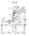
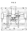
- Figs. 1, 2 and 3 are respectively an elevational view, side elevational view and a plan view of the exterior of an embodiment of the present invention.
- referential symbol V denotes a part supplying means, S a chute means, INS an insertion unit, T an X-Y table, C a clinching means and F a body frame.
- the part supplying means V is disposed in an inclined manner with the insertion unit INS facing downwards, and is provided with stacked magazines 2 each of which accomodates a multiplicity of electron parts. The lowermost magazine 2 is discharged after it is confirmed that no part is left therein, and thereafter the next magazine 2 descends to automatically supply an electron part.
- Electron parts supplied from the magazine 2 consistently go to the location of a supply positioning end 3 of the chute means S by virtue of gravitational effect.
- Some electron parts have such high centers of gravity and are so easy to overturn that the effect of gravity-drop cannot be utilized.
- the parts may be arranged horizontally and be forcibly fed to the supply positioning end 3 by vibration or the like.
- in the case of supplying loose parts it is possible to supply them to the supply position positioning end 3 through an inclined part feeder, a straight feeder or the like.
- the insertion unit INS is composed of a set of four elevating and descending hands 5.
- An insertion unit transferring means 6 has a mechanism for transferring the insertion unit INS in the direction X shown in Fig. 1.
- This structure makes it possible to insert a multiplicity of kinds of parts of any number (N) provided that the number of hands is a factor of N, and to conduct the discharge of a defective part, lead correction or automatic replacement of a chuck by making use of an idle station.
- the X-Y table T which drives a screw shaft (ball screw) by a servo-motor, carries out positioning in two directions orthogonal to each other in the same plane.
- the clinching means C is composed of a set of four clinching units 9 which are correspondent with the hands 5 and which clinch or crush the leads of an electron parts such as to prevent the electron part from slipping off the printed board after insertion.
- the clinching units 9 includes a mechanism for rotating an electron part by 90 degrees, a lead detection mechanism for confirming that a part has been inserted and a mechanism for holding a warp of the printed board.
- the hand 5 is provided with a mechanism for grasping an electron part and a mechanism for rotating the electron part by 90 degrees.
- the control means CON stores a device for controlling the entire operation.
- the insertion unit transferring means 6 Under the instruction of the control means CON, the insertion unit transferring means 6 first transfers the insertion unit INS to a position above the selected supply positioning end 3. The four hands 5 of the insertion unit INS are next lowered to grasp the electron part at the supply positioning end 3 and are then elevated, whereupon the insertion unit INT is transferred to a position above the clinching means C having clinching units 9 which correspond to each hand 5. Thereafter under the instruction of the control means CON the X-Y table T transfers a printed board 12 which is set on the upper table such that an electron part receiving hole of the printed board 12 corresponds to the insertion position of the part which is held by one of the hands 5 of the insertion unit INS.
- position correction by means of an optical quarter-wave plate it fits the insertion position by detecting and correcting the amount of deviation, when the part insertion hole of the printed board is not in the correct position.
- the clinching unit 9 of the clinching means C under the printed board 12 which is in correspondence with the insertion hand 5 is elevated and assumes a state of waiting for insertion while holding the warp of the printed board 12.
- the selected hand 5 is next lowered to insert the leads of the electron part held by it into the electron part receiving hole of the printed board 12, and an optical sensor built in the clincher of the clinching unit 9 detects and clinches the leads.
- the electron part is judged as a mis-insertion and is discharged to a defective part discharging means.
- This action is called "retry" and the number of times retry is attempted can be set freely.
- retry is carried out at most three times, and when retry has been unsuccessfully attempted three times, the apparatus indicates abnormality and stops before a fourth retry. In this way, the action of positioning in relation to the printed board 12, insertion and clinching is repeated for every part held by the hand 5, and the hand 5 then returns to the initial action of grasping a part at the supply positioning end 3 and this sequence of actions is repeated.
- the structure of each means for performing the above-described actions will be explained in detail in the following.
- This supplying means V essentially consists of a magazine charging means Va, a part escape means Vb, and a lead correcting mechanism Vc.
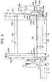
- Figs. 4, 5 and 6 are a side elevational view, a plan view and a rear view, respectively, of the magazine charging means Va.
- this charging means Va utilizes gravity-drop, it is fixed at an incline of about 40 degrees.
- This charging means Va accommodates about 15 to 20 stacked magazines 120, which are supported by forward magazine guides 103a, 103b and 105 arranged ahead of the magazine 120 and rear magazine guides 102, 102b and 104 arranged at the back of the magazine 120.
- a magazine retainer 106 supports the lower end of the magazine 120 from the lowermost layer and the other escape retainer 107 is situated at a position where it fits into the depression (120a) in the center of the rear end of the next magazine 130 (Fig. 7).
- the magazine retainer 106 has a drive solenoid 108 attached to an arm 109 portion with a pin 108a in such a manner that the upper end thereof is rotatable.
- the magazine retainer 106 is rotatable around a shaft 106a, and has a slit 106b for driving the magazine retainer 107.
- the magazine retainer 107 is rotatable around a shaft 107a, and the rotation is urged in the direction opposite to the retainer 106 by a pin 107b inscribed in the slit 106b.
- the magazine retainer 106 is urged by a spring 121 in a direction which enables it to support the rear end of the lowermost magazine 120 in the normal state.
- a switch 115 for detecting the last magazine remaining after the other magazines have been discharged.
- the actuator 114 of the switch 115 is disposed such as to project from the groove 105a formed on the guide 105 and to be actuated by the end surface of the second lowermost magazine 130.
- the end portion llla facing the magazine 120 of a chute rail 111 of the chute means S projects slightly (about 5 mm) from the forward magazine guide 105, and has an appropriate difference in level lllb at its end such as to fit into the depression 120a of the fore end of the magazine 120 and enable smooth drop of an electric part when the magazine 120 is located at the right position, as is shown in Fig. 8.
- Magazines 120 each of which is charged with 15 to 20 electron parts P are laid one on top of the other between the forward and rear guides with their openings facing the forward magazine guides after the plugs employed for retaining electron parts have been removed.
- the fore end 120a of the magazine 120 is supported by the end portion llla of the chute rail 111 and the rear end of the magazine 120 is supported by the magazine retainer 106.
- In the middle a space is provided which allows an empty magazine to be discharged.
- the lowermost magazine has the magazine 130 and the other magazines above it, and when the lowermost magazine 120 is discharged, each of these remaining magazines moves down to the next level in succession.
- the magazine retainer 106 moves in the direction of the arrow, as described above, and releases the rear end of the lowermost magazine 120, the other magazine retainer 107 is driven to support the rear end of the next magazine 130.
- the slit 106b moves in the direction opposite to the driving direction of the magazine retainer 106 around the shaft 106a, as is indicated by the arrow, and drives the pin 107b which is secured to the magazine retainer 107 in the same direction, thereby driving the magazine retainer 107 around the shaft 107a in the direction indicated by the arrow.
- empty magazines 120 are discharged downwardly in succession, and magazines containing electron parts are located at the opening portion 113 for feeding to the inserting machine body by means of the chute rail 111.
- a warning signal giving a prior warning of the impending exhaustion of the supply of parts is output by releasing the actuator 114 of the switch 115.
- the magazine retainer 106 is formed such as to have a U-like configuration in cross section and the position 150 of the supporting point of the shaft 106a is determined such as to be substantially the same as the position of the rear end of the magazine 120. This is useful for preventing the generation of moment force which would rotate the magazine retainer 106 rightwardly or leftwardly as a result of the force produced by the dropping of the magazine 120, and for preventing the magazine retainer 106 from being pushed in the direction indicated by the arrow, in resistance to the force of the spring 121, by virtue of the impact force produced when adding a magazine from above or dropping all the magazines, and thus prevents any undesirable dropping of a magazine.
- Electron parts P in the magazine 120 pass through the chute rail 111 and drop to the supply positioning end 3 where the insertion hand 5 conducts the action of grasping. Between the chute rail 111 and the supply positioning end 3 an escape mechanism for feeding parts individually as they drop from the magazine 120 in succession.
- Fig. 9 is a side elevational view of the escape mechanism Vb and Fig. 10 a plan view thereof.
- This escape mechanism is composed of a detent 312 for temporarily stopping the dropping electron parts P, a solenoid 312 for vertically moving the detent 314, a support pin 314b for rotatably supporting the detent 314, a spring 317 which is urged in the normal state such as to press the end of the detent 314a through the support pin 314b and thereby to retain the parts, a controllable spring plunger 316 which is fixed on the detent 314 at a position above the part P2 next to the part Pl to be retained, and members 313, 311 for fixing the solenoid 312, spring 317, and support pin 314b.
- the operation of the escape mechanism is as follows.
- the electron parts P which have dropped from the magazine 120 through the chute rail 111 are retained by the end portion 314a of the detent 314 and are stopped in a line.
- the sensor 302 confirms a presence of a part and outputs a signal to the solenoid 312
- the plunger 315 is urged and draws the detent 314 upwards in resistance to the force of the spring 317, whereby the detent 314 moves around the support point 314b in the direction indicated by the arrow.
- the part Pl is released to drop down the chute rail 111.
- the spring plunger 316 is pushed downwardly in the direction indicated by the arrow and presses the upper surface of the next part P2. In this way, only the part Pl is released.
- the urging of the solenoid 312 is stopped, whereby the detent 314 is restored to its original state by the force of the spring 317, and the end portion of the detent 314a returns to the retaining state.
- the spring plunger 316 moves upward as it presses the part P2, whereby the part P2 is released and drops to the point where it is retained by the detent end 314a. Repetition of this process allows the parts which have dropped from the magazine 120 in succession to be fed to the handling portion one by one.
- the use of the spring plunger 316 solves the problem of parts lacking in uniformity of height, and enables a stable escape action.
- the electron parts P which are separated from each other by the escape mechanism Vb drop onto the inclined chute rail 111 of the chute means S and drop by gravity to the supply positioning end 3, where they are retained by stopping means SS precisely at the stop position.
- Fig. 11 is a side elevational view of the stopping means SS
- Fig. 12 a plan view thereof
- Fig. 13 an elevational view thereof.
- the stopping means SS is composed of a stopper project 331, a pin 332 which rotatably retains the stopper barn 331, and a fixing member 333 for holding the pin 332.
- the fixing member 333 is secured to the chute rail 111 by bolts 334 in such a mammer that microadjustment control is possible.
- the chute rail lll is angled such that the inclined part of the rail changes midway into a horizontal rail, but in some cases, depending upon the structure of the hand, the entire length of the chute rail may be an inclined rail at a constant angle and be retained by the stopping means SS.
- the electron part P which has fallen to the stopping means SS is retained by the stopper cord 331.
- a referential numeral 304 denotes a supporting member which functions to securing the side of the positioning end 3 of the chute means S to the frame of the body F.
- the object of lead correction of an electron part is to correct inward deflection of the lead ends of a part which has leads arranged in pairs such as an IC part, and this invention is characterized in that lead correction is conducted successively at some position on the chute rail 111.
- Fig. 11 is a side elevational view of the lead correction means Vc and Fig. 14 an elevational view thereof.
- This means Vc is composed of an upper guide 353 for holding a part P from the topside at the time of correction and two correction claws 352 which hold the part P from the lower side, an air cylinder 351 for vertically moving the claws 352 and a side plate 360 for supporting the part P.
- the upper guide 353 and the correction claws 352 each have configurations which corresponds to the electron part P, and the correction claws 352 have configuration which allows them to be lifted from both sides of the rail 111 in order to prevent interference with the chute rail 111.
- the width of the chute rail may be changed, as occasion demands, such as to prevent such interference.
- the end portion 352a of the correction claws 352 is designed to have a width narrower than the distance between a pair of leads of a part before correction and to have, on both sides, slanting surfaces tapering upwardly and converging at an angle suitablee for spreading each pair of leads with the ascent of the claws 352.
- this means is also provided with a retaining member 356 which is supported such as to be rotatable around a support point 358, a solenoid 354 and a plunger 357 for vertically moving the retaining member 356, a spring 359 which urges the retaining member 356 in the normal state, and side plates 360 for fixing the support point 358, the solenoid 354, the spring 359 and the like.
- a sensor 303 for detecting a part P, sensors 304a and 304b for detecting the upper and lower edges of the air cylinder 351, and a sensor 305 for confirming the vertical motion of the retaining member 305 may be attached in accordance with demands.
- the correcting means 350 is usually provided between the escape means 310 and the supply positioning end 3.
- a part P is fed from the escape means 310 individually, it drops onto the chute rail 111 and is retained by the retaining member 356.
- the correction claws 352 are elevated by the air cylinder 351.
- the upper surface of the part P is fixed by the guide 353, and the pairs of leads PF of the part P are spread outwardly by virtue of the inclined surfaces 352a.
- the air cylinder 351 and the correction claws 332 are lowered and the retaining member 356 is lifted by virtue of the urging of the solenoid 354, whereby the part P released from the retaining drops onto the chute rail 111 by gravity and arrives at the part stopper means 330.
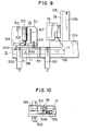
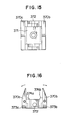
- correction claws having a structure the plan view of which are shown in Fig. 15 and the side elevational view of which are shown in Fig. 16.
- These correction claws 370a and 370b are rotatably supported by a support pin 372 which is secured to a supporting member 371.
- the correction claws 370a and 370b are situated on both sides of the supporting member 371 and have adjustment screws 373a and 373b, respectively, which makes the working range controllable.
- the supporting member 371 is secured to the rod of the air cylinder 351, as in the case shown in Fig. 14, and moves vertically.
- the correction claws 370a and 370b are provided with protrusions 374a and 374b, respectively, on the side surfaces facing the chute rail 111.
- the height of the protrusions is determined by an appropriate divergence of the correction claws 370a and 370b.
- the remaining structural features are substantially the same as the correction claws shown in Fig. 14.
- the operation of the correction claws 370a and 370b is as follows.
- the correction claws 370a and 370b are elevated at the same time when the supporting member 371 above the cylinder 351 is lifted, and immediately before the upper limit the protrusions 374a and 374b come into contact with the lower surface of the chute rail 111.
- the air cylinder 351 continues to be elevated and pushes up the support pin 372, whereby the moment force which opens the correction claws 370a and 370b outwardly around the support pin 372 is applied to the claws. In this way the end portions of the claws are opened in the directions indicated by the arrows in Fig. 17, thereby spreading the leads RF outwardly.
- This divergence can be controlled so as to be suitable for the leads PF of the part by the adjustment screws 373a, 373b, the protrusions 374a, 374b, the cylinder stroke employed and the like.
- this control mechanism can correct an inward deflection of the lead PF by the ascending action, or, if necessary, by the ascending and opening action, of the inlined surfaces of the correction claws 352.
- the leads PF which has been spread outwardly are introduced to the fingers of the hand 5 by means of a guide groove formed for the purpose of guiding leads and are positioned accurately at the time of grasping.
- This correction mechanism is characterized in that the correction means 350 can be disposed between the escape mechanism 310 and the stopper means 330 by extending the chute rail 111, that continuous correction is enabled by taking advantage of the fact that parts are individually fed from the escape mechanism 310, and that the entire mechanism can be made compact by reducing the widthwise size thereof.
- the fixed guide 353 is on the upper side of the rail and the claws 352 are on the lower side, but it is possible to use a structure the other way with the driving source on the upper side.
- the insertion unit INS grasps an electron part P located at the supply positioning end 3 and inserts it into a predetermined position of the printed board 12 which has been located by the X-Y table T.
- This unit 4 is mainly composed of hands for grasping electron parts P, a hand elevating means for elevating and lowering the hands and a hand transferring means for transferring the hand in the direction X and Y shown in Figs. 1 and 2.
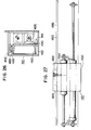
- Figs. 17 to 21 show the insertion unit INS, wherein Fig. 17 is an elevational view of the insertion unit INS, Fig. 18 a side elevational view thereof; Fig. 19 a cutaway side elevational view of the hand transferring means of the insertion unit INS; Fig. 20 a cutaway side elevational view illustrating the hand transferring means; and Fig. 21 a partially cutaway plan view of the hand transferring means illustrating the transfer in the direction X.
- the hand will first be explained.
- the hand 5 has fingers 401 which grasp an electron part P by closing and opening action; pins 402 which are supporting points for the opening and closing action; finger bodies 403 for holding the fingers 401; a swivel air actuator for swivelling the finger bodies 403 which consists of a vane 404, a vane housing 405, a packing 406, and a bolt 407 for securing the vane 4G4 to the finger body 403; a single-acting air cylinder which consists of a piston rod 408, a piston 409, a cylinder tube 410, a cylinder cover 411, a compression spring 412, a packing 413, and a bolt 414 for connecting the piston rod 408 and the piston 409; ball bearings 415 which are sliding portions of the piston rod and which transmit the action of the piston rod 408 to the fingers 401 so as to open or close the fingers 401; pins 416 for attaching the ball bearings to the fingers 401; a detection lever 417 which operates in combination with the opening
- the hand elevating means is mainly composed of a guide bar 420 for elevating or lowering the hand 5 so as to insert the electron part P held by the fingers 401 into the printed board 12; a cover ring 421 for retaining the guide bar 420 to the cylinder cover 411; a linear motion ball bearing 422 for guiding the guide bar 420; a holder 423 for holding the linear motion ball bearing 422; an insertion air cylinder 424 for elevating or lowering the hand 5 by elevating or lowering the guide bar 420; and a connecting plate for connecting the air cylinder 424 and the guide bar 420.
- the hand transferring means are composed of a hand holding plate 426 which holds a plurality of hands 5 and hand elevating means; a cross roller guide 427 which is designed to elevate or lower all the hands 5 simultaneously by elevating or lowering the hand holding plate 426; a bearing box 428 for holding the cross roller guide 427; an elevating air cylinder 429 for elevating or lowering the hand holding plate 426; a connecting plate 430 for connecting the elevating air cylinder 429 and the hand holding plate 426, a hand holding plate 431 for holding the elevating air cylinder 429 and the bearing box 428; an air cylinder 433 attached to a hand transferring plate 432 which horizontally moves an electron part from the supply positioning end 3 to the position where it is inserted to a printed board; a guide bar 434, a linear motion ball bearing 435; holding plates 436 which hold the linear motion ball bearing 435 and the air cylinder 433; Y axial moving frame 437 for moving the hand 5 in the direction Y so as to take a desired part out of
- the finger 401 is open, the insertion cylinder 424 is elevated, the elevating air cylinder 429 is at the upper limit, the air cylinder 433 is at the withdrawal end, and the finger 401 is stopped right over the supply positioning end 3.
- all the insertion cylinders 424 are lowered ready for grasping of the electron parts P by the fingers 401.
- air is introduced into the lower portion of the piston 409 in the cylinder tube 410, the piston 409 is elevated and in conjunction with it the piston rod 408 is also elevated. This action lifts the ball bearings 415 which are retained in the fingers 401 and the fingers 401 are rotated around the pins 402 to grasp thee electron part P.
- the transmission ring 418a is elevated, and the detection lever 417 which is engaged with the transmission ring 418a rotates around the holding fitting 418b.
- This detection lever 417 interrupts the sensor 419 and detects that the fingers are closed.
- the insertion cylinder 424 is elevated up to the upper limit.
- the part grasped at the supply positioning end be inserted into the printed board 12 in a state wherein the part P has been rotated by 90 degrees from the position at which it was grasped
- air is blown into the vane housing 405 to rotate the vane 404 and to swivel the fingers 401 which are indirectly connected to the vane 404, thereby rotating the part P.
- the elevating air cylinder 429 is lowered.
- the corresponding insertion air cylinder 424 is lowered, whereby the part P is inserted into the printed board 12.
- the compression spring 412 presses and lowers the piston 409.
- the fingers 401 are opened and the detection lever 417 is restored to its original position and interrupts the sensor 419.
- the insertion cylinder 424 is elevated.
- the insertion of the first electron part P is completed in this way, and a second and later parts P are subsequently inserted.
- the second and later insertions are conducted only by elevation and lowering of the insertion cylinder 424 and the opening action of the fingers 401.
- the elevating cylinder 429 is elevated.
- the air cylinder 433 withdraws and returns to its original position.
- the hand 5 is further composed of a piston rod 408 - 1, a pusher 408 - 2, a compression spring 408 - 3, a pusher retainer 408-4 and a locking nut 408 - 5.
- this hand 5 grasps the electron part P at the supply positioning end 3 and when the insertion cylinder 424 is lowered, the pusher 408 - 2 comes into contact with the part P and withdraws. In this state the electron part P is grasped for insertion into the printed board 12.
- the pushers 408 - 2 presses the electron part P downward by the force of the compression spring 408 - 3 so as to insert the leads PF deeper into the printed board 12.
- the hand 5 When the hand 5 is transferred to a desired supply positioning end 3, it is transferred by the rotation of a ball screw 442 driven by a motor 444.
- the hand 5 may also be transferred by means of a chain or a wire in place of the ball screw, or by means of a rack and a cyllinder, or an air cylinder.
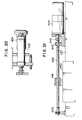
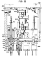
- Figs. 22 to 27 show an improved insertion unit the improvements of which are chiefly applied to the hands 5.
- Fig. 22 is a partially cutaway elevational view-of the insertion unit
- Fig. 23 a side elevational view thereof
- Fig. 24 a cutaway bottom view of the rotating means of a chuck
- Fig. 25 a cutaway plan view of a means for removing the chuck
- Figs. 26 and 27 are respectively a cutaway side view and a rear view of a hand transferring means.
- this unit will be explained with reference to the Figures.
- the insertion unit has new features in that the process of inserting the electron part P on the supply positioning end 3 into the printed board 12 is shortened, that a single swivel actuator swivels the plurality of hands 5 simultaneously, and that the hands 5 are easily replaceable.
- This insertion unit INS includes chucks 458, the hands 5 which have the main bodes for rotatably supporting the chucks 458, and a transferring means which transfers the hands 5 in the X axial direction.
- the chuck 458 will be explained first.
- the chuck 458 is composed of fingers 450 for grasping the electron part P by an opening and closing action; pins 451 which are supporting points for the opening and closing action of the fingers 450; a finger body 452 for holding the fingers 450; a piston 453 for opening or closing the fingers 450; a compression spring 454 for returning the poiston 453; a finger joint 455 which serves as a joint when the fingers 450 are replaced; a stopper 456 for fixing the chuck 458 when it is jointed; and a tension spring 457 for compressing the stopper 456.
- the main body of the hand 5 includes a joint shaft 459 for putting air into the chuck 458 and jointing the chuck 458; an elevating cylinder 460 for elevating or lowering the joint shaft 459; a connecting plate 461 which connects the joint shaft 459 and the elevating cylinder 469; a linear motion bearing 462 for guiding the joint shaft 459; a bearing holder 463 which retains the linear motion bearing 462; a radial bearing 464 which retains the outer periphery of the bearing holder 463; a hand holder 464 which holds the radial bearing 464; a swivel air cylinder 466 for swivelling the chuck 458; a swivel pusher 467 which is actuated by the swivel air cylinder 466; a rack 468 which engages with the swivel pusher 467 and which is divided at every chuck 458; rings 469 provided between the divided portions of the rack 468 and at both ends thereof; compression spring
- the transferring means includes an upper guide rail 488 which retains and guides the hand transferring means 481; an upper guide rail bearing 489; a lower guide rail 490; a cam follower 491; a hand transferring means plate 492 which holds the upper guide rail bearing 489 and the cam follower 491; a hand transferring means frame 493 which holds the upper guide rail 488 and the lower guide rail 490; a transferring cylinder 494 for transferring the hand transferring means frame 493 and the hand transferring means plate 492; and a connecting plate 495 which connects the hand transferring means plate 492 and the transferring cylinder 494.
- the swing cylinder 484 advances to swivel the hand 5 to a position right over the supply positioning end 3.
- the elevating cylinder 460 is next lowered.
- air is drawn into the finger body 452 through the joint shaft 459, and the fingers 450 are closed to grasp the electron part P.
- the elevating cylinder 460 is elevated after grasping the part P and the swing cylinder 484 is withdrawn, the hand 5 is swivelled to a position above the printed board 12.
- the swivel air cylinder 466 By actuating the swivel air cylinder 466 during the swivel of the hand 5, the swivel pusher 467 is actuated and the ring 469 push the compression spring 470 and the rack 468.
- This action of the rack 468 enables the pinion 473 to rotate, and the roller 474 which is integral with pinion 473 to rotate the joint shaft 459 and the fingers 450, whereby the electron part P can be rotated.
- the elevating cylinder 460 When the fingers 450 holding the electron part P arrive at a position above the printed board 12, the elevating cylinder 460 is lowered for insertion of the electron part P into the printed board 12.
- the piston 453 When air which has been drawn into the finger body 452 is stopped after the insertion of the electron part P, the piston 453 is restored to its original position by means of the compression spring 454, and the fingers 450 are opened. Thereafter the elevating cylinder 460 is lifted to insert a second electron part P.
- the stopper 456 In the case of removing the chuck 458 from the joint shaft 459, the stopper 456 is pushed toward the outer periphery of the chuck 458 in order to be removed from the groove of the joint shaft 459 and the chuck is lowered for removal.
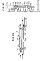
- Figs. 28, 29 and 30 show the structure of the X-Y table T which carries the printed board 12 and positions it by moving it on the horizontal plane.
- Fig. 29 is a plan view of the X-Y table T
- Figs. 30 and 31 are respectively an elevational view and a side view thereof.
- the X-Y table T is composed of an upper table 701 and a lower table 702.
- the two tables 701 and 702 are slidable in the direction Y and the direction X, which is orthogonal to Y, respectively.
- the lower table 702 is mounted through bearings 705 on a pair of rails 704 which are laid on a bed plate 703 in the direction X.
- the upper table 701 is mounted through bearings 710 on a pair of rails.709 which are laid on the lower table 702 in the direction Y.
- the lower table 702 is driven by rotating a motor 717 which is mounted on the bed plate 703 and thereby rotating a male screw 707 through a coupling 706 and sliding a female screw 708 which is secured to the lower table 702.
- the upper table 701 is driven by rotating a motor 711 which is mounted on the lower table 702 and thereby rotating a male screw 713 through a coupling 712 and sliding a female screw 714 which is secured to the upper table 701.
- Each of the driving motors 711 and 717 is provided with encoders 715 and 716, respectively, which detect an appropriate position in the positioning of the X-Y table T.
- Figs. 31, 32, 33 show an example of a frame device for holding the printed board which is mounted on the upper table 701, wherein Fig. 31 is a plan view of the device, and Figs. 32 and 33 are respectively an elevational view and a side elevational view thereof.
- Figs. 34 and 35 are detailed views of a pin lever and a printed board stopper, respectively.
- This printed board holding device is provided with a pair of guide rails 721 and 722 which have guide grooves for holding the printed board 12 and which are parallel to each other in the direction X.
- One guide rail 721 is fixed and the opposite guide rail 722 is slidable in the direction Y in accordance with the width of the printed board 12 to be carried.
- This rail 723 can be fixed by tightening T bolts 723 in slits 720 which are formed on the upper table 701.
- Levers 725 having pins 724 for positioning the printed board 12 and a blocking stopper 726 are provided on the side of the fixed rail 721.-
- the levers 725 are attached to a rotatable shaft 728 which is parallel to the fixed rail 721 and are movable in the direction of the shaft in accordance with the length of the printed board 12.
- the lever 725 is clamped by a spring 731 in the normal state and is unclamped by pressing the end of the lever.
- Fig. 35 is a detailed side elevational view of the printed board stopper 726.
- the printed board stopper 726 which is connected to the shaft 728 through a bearing 729, is located at the blocking position by a spring 730 in the normal state and is released by pushing the lever of the blocking stopper 726.
- a dog 732 is provided at a position at the stroke end of the X-Y table T where the pin lever 724 and the printed board stopper 726 come into contact with the dog 732.
- the pin lever 725 or the printed board stopper 726 By pushing the pin lever 725 or the printed board stopper 726 by the dog 732, the positioning pins 724 and the printed board stopper 726 are released. In this way, without providing an actuator on the sliding X-Y table T, the levers are actuated by making use of the positioning device of the X-Y table.
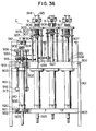
- the clinching means C will next be explained.
- the clinching means has four clinching units 9. Since the power source for the four clinching units 9 is air pressure, pressurized air is put into the clinching means C by way of a pipe from the power source.
- the pressurized air is divided by an air regulator into two, namely, air the pressure of which is low (hereinunder referred to as low pressure air) and the air the pressure of which is that existing before being lowered (hereinunder referred to as normal pressure air), and each of them is controlled by the control means CON so as to actuate the four clinching units.
- Figs. 36, 37 and 38 show the clinching means C, wherein Fig. 36 is a partially cutaway view of the clinching means C, Fig.
- a referential numeral 901 represents a single-acting double rod cylinder, 902 an auxiliary rod, 903 a pre-load adjusting nut, 905 a parallel adjusting nut, 906 a pre-load spring, 907 a cover ring, 908 a clinch actuator rod, 909 a roller, 910 a roller retaining shaft; 911 a clincher block for transmitting a clinching action; 912 a clincher set-screw; 913 a clincher shaft, 914 printed board supporter; 915 a clincher; 916 a clinching unit elevation stopper, 917 a clinching unit elevation adjusting nut, 918 a clinching unit swivel plate; 919 a bearing, 920 a clinching unit swivel plate; 921 a bearing slip stopping plate, 922 a bearing
- the clinching unit swivel plate 918 is screwed to the upper portion of the sigle-acting double rod cylinder 901 and the clinching unit swivel plate 920 is screwed to the lower portion of the cylinder 901.
- the clinching unit swivel plate 920 on the lower portion is inserted into the bearing 922 and is prevented from slipping off by the snap ring 923.
- the bearing 922 is inserted into the bearing receiving hole on the lower clinching unit supporting plate 803, and is attached to the lower clinching unit supporting plate 803 by the bearing slip stopping plate 921.
- Three auxiliary rods 902 are provided such as to penetrate through the upper clinching unit supporting plate 918.
- each auxiliary rod 902 On the upper portion of the three auxiliary rods 902 the pre-load supporting plate 918 is provided such that the three rods penetrate the supporting plate 918.
- a cover ring 907 is disposed, and the pre-load supporting plate 903 is disposed above each ring 907.
- the uppermost end of each auxiliary rod 902 is threaded and after the parallel adjusting nut 905 is threaded to each rod 902, each rod 902 is screwed into each corresponding hole formed on the clinching unit head base 936.
- the clinching unit head base-936 and the pre-load supporting plate 903 are adjusted to be parallel and horizontal and the pre-load of the pre-load spring 906 is also adjusted by the parallel adjusting nut 905.
- each of the three auxiliary rods 902 is inserted into each corresponding hole formed on the clinching unit elevation stopper 916, and at the lowermost threaded end of each auxiliary rod 902 the clinching unit elevation adjusting nut 917 is mounted to adjust the stroke of the elevation of the clinching unit 9.
- the bearing 919 is provided on the outer periphery of the clinching unit swivel plate 918, and the bearing 919 is inserted into the bearing receiving hole on the upper clinching unit supporting plate 802.
- the upper and lower clinching unit supporting plates 802 and 803 holding four clinching units 9 of the above-described structure are supported by the two side plates 801 and the back plate 805 and the entire portion of the clinching means C is secured to the main body by the adapter plate 804.
- the elevating and lowering action of the clinching unit 9 is as follows. Low pressure air is first put into the air inlet 935 of the single-action double rod cylinder 901. The low pressure air acts within the cylinder 901 and elevates the upper cylinder rod 924. This elevating force is transmitted from the clinching unit head base 936 to the three auxiliary rods 902 through the pre-load spring 906, thereby elevating the three auxiliary rods 902 and the clinching unit head base 936 together with the upper cylinder rod 924.
- the clinching unit elevation stopper 916 which is attached to the three auxiliary rods 902 abuts the upper clinching unit supporting plate 802
- the upper cylinder rod 924 is stopped through the three auxiliary rods 902
- the pre-load compression spring 906 is compressed by the parallel adjusting nut 905 such as to be pre-loaded. This state is illustrated in the first action shown in Fig. 36.
- the pressure of the low pressure air is balanced by the inner descending force of the single-acting double rod cylinder 901, the gravity force of that which has been elevated at the ascending time and the force applied on the pre-load spring 906.
- the force applied on the pre-load spring supports the printed board supporter 914 so that the printed board is not warped.
- the ascending stroke at this time is adjusted by the clinching unit elevation adjusting nut 917.
- Each of the two cylindrical rollers 909 is attached to the roller retaining shaft 910 such as to be rotatable in the peripheral direction.
- the roller retaining shaft 910 is attached to the corresponding clincher blocks 911.
- the clincher blocks 911 are attached symmetrically by the clincher shaft 913.
- To each clincher block 911 above the clincher shaft 913 is attached the clinchers 915.
- the sensor 937 for detecting the presence of the leads of the part in the direction in which the clinchers 915 move is provided within each clinder 915. Both ends of the clincher shaft 913 are held by the printed board supporter 914.
- the rollers 909 are disposed such as to be symmetrical with each other in the axial direction of the clincher shaft 913, and in the normal state the two rollers 909 are in contact with each other by virtue of the effect of gravity or the spring force provided between the two retaining shafts 910.
- the cylindrical clinch actuator rod 908 is disposed below the abutting rollers 9.
- the clinching action of the clinchers 915 will be next explained.
- the air pressure source is changed from the low pressure air to the normal pressure air, and the air to be supplied to the air inlet 935 is also changed from the low pressure air to the normal pressure air.
- This difference in pressure between the normal pressure air and the low pressure air compresses the pre-load spring 906, whereby the pre-load supporting plate 903, the upper cylinder rod 924 and the clinch actuator rod 908 are elevated.
- the pre-load spring 906 pushes the pre-load supporting plate 903 downwardly such as to stretch itself, and the pre-load supporting plate 903 abuts the cover ring 907.
- the upper cylinder 924 is lowered to assume its normal state, as is shown in Fig. 36.
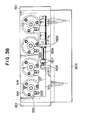
- Fig. 38 is a cutaway plan view of the rotating mechanism.
- the clinching unit rotating plate 918 is provided with the rotation transmitting shaft 933 in a circumferentially intermediate position between any two adjacent holes selected from among the three holes into which the three auxiliary rods 902 are inserted.
- the bearing 932 is provided on the outer periphery of the rotation transmitting shaft 933.
- the rotation transmitting plate 931 which retains the bearing 932 of each of the four clinching units 9 with the same pitch
- the-transmitting plate 928 which connects the rotation transmitting plate 931 and the cylinder rod 934
- the rotation angle adjusting nut 927 which positions the transmitting plate 928 and the cylinder rod 934
- the rotation stopper 926 for blocking the cyoinder rod 934 which is attached to the back plate 805
- the cylinder adapter plate 929 for securing the double-acting cylinder rod 930 to the back plate 805.
- the operation will be explained in the following.
- the linear motion of the double-acting cylinder rod 930 is transmitted to the linear motion of the rotation transmitting plate 931 through the transmitting plate 928, and this linear motion is converted into the rotary motion which rotates the clinching unit rotating plate 918 around the single-acting double rod cylinder 901 through the bearing 932 and the rotation transmitting shaft 933.
- This rotary motion is transmitted to the three auxiliary rods 902 and the single-acting double rod cylinder 901 through the clinching unit rotating plate 918, thereby rotating the clinching unit 9.
- Since the rotation transmitting plate 931 connects the four clinches 9, all the four clinching units 9 rotate simultaneously.
- the rotation angle can be adjusted by changing the distance of the linear motion of the rotation transmitting plate 931.
- the position of the lower cylinder rod 925 is detected by a sensor.
Landscapes
- Engineering & Computer Science (AREA)
- Manufacturing & Machinery (AREA)
- Microelectronics & Electronic Packaging (AREA)
- Supply And Installment Of Electrical Components (AREA)
Applications Claiming Priority (2)
| Application Number | Priority Date | Filing Date | Title |
|---|---|---|---|
| JP44015/84 | 1984-03-09 | ||
| JP59044015A JPS60189291A (ja) | 1984-03-09 | 1984-03-09 | 電子部品の自動插入装置 |
Publications (2)
| Publication Number | Publication Date |
|---|---|
| EP0154848A2 true EP0154848A2 (de) | 1985-09-18 |
| EP0154848A3 EP0154848A3 (de) | 1989-05-17 |
Family
ID=12679854
Family Applications (1)
| Application Number | Title | Priority Date | Filing Date |
|---|---|---|---|
| EP85101837A Withdrawn EP0154848A3 (de) | 1984-03-09 | 1985-02-20 | Vorrichtung zum automatischen Einstecken eines elektronischen Bauteils |
Country Status (3)
| Country | Link |
|---|---|
| US (1) | US4637134A (de) |
| EP (1) | EP0154848A3 (de) |
| JP (1) | JPS60189291A (de) |
Cited By (3)
| Publication number | Priority date | Publication date | Assignee | Title |
|---|---|---|---|---|
| EP0189290A3 (en) * | 1985-01-21 | 1987-08-05 | Fuji Machine Mfg. Co., Ltd. | Apparatus for positioning substrates of different sizes of printed-wiring boards |
| DE3625019A1 (de) * | 1986-07-24 | 1988-01-28 | Siemens Ag | Vorrichtung zur halterung von leiterplatten |
| RU2129113C1 (ru) * | 1993-09-21 | 1999-04-20 | Эйсай Ко., Лтд. | Циклогексановое производное, способ расслабления гладкой мышцы млекопитающего |
Families Citing this family (11)
| Publication number | Priority date | Publication date | Assignee | Title |
|---|---|---|---|---|
| US4850785A (en) * | 1987-03-13 | 1989-07-25 | Quality Automation, Inc. | Eprom feed apparatus |
| DE3722587A1 (de) * | 1987-07-08 | 1989-01-19 | Guglhoer Bernhard Praezision | Vorrichtung zum gleichzeitigen befestigen einer anzahl von kontaktstiften in elektronischen leiterplatten |
| DE4002075A1 (de) * | 1990-01-25 | 1991-08-08 | Antriebs Steuerungstech Ges | Handhabungsvorrichtung und verfahren zum handhaben von werkstuecken |
| JP2906371B2 (ja) * | 1993-09-20 | 1999-06-21 | 富士通株式会社 | 系の切替え方式 |
| US5828310A (en) * | 1997-05-20 | 1998-10-27 | Motorola, Inc. | Indicator system having plurality of feeders and actuators arranged to selectively actuate a sensor |
| WO2000016602A1 (en) * | 1998-09-10 | 2000-03-23 | Matsushita Technology (S) Pte Ltd | A method of supplying components to an electronic component mounting or insertion machine |
| US6192576B1 (en) * | 1999-06-15 | 2001-02-27 | Advanced Micro Devices, Inc. | Mechanism for loading a respective fuzz button into each of a high number of button holes within an IC contactor |
| RU2426284C2 (ru) * | 2009-11-02 | 2011-08-10 | ОАО "Концерн "Моринформсистема-Агат" | Паяльная головка автомата пайки электроэлементов на печатные платы |
| LT6438B (lt) | 2015-10-21 | 2017-08-25 | Uab "Neurotechnology" | Bekontakčio manipuliavimo įrenginys, surinkimo būdas ir 3d spausdinimas |
| RU182904U1 (ru) * | 2017-10-27 | 2018-09-05 | Акционерное общество "Головное производственно-техническое предприятие "Гранит" | Устройство для ремонта сменных элементов радиоэлектронной аппаратуры |
| CN110076541B (zh) * | 2019-06-05 | 2024-06-04 | 深圳市昊云智能科技有限公司 | 一种装配设备的线圈卡环上料装配机构 |
Family Cites Families (6)
| Publication number | Priority date | Publication date | Assignee | Title |
|---|---|---|---|---|
| DE2265183A1 (de) * | 1971-07-26 | 1976-10-14 | Matsushita Electric Ind Co Ltd | Montagevorrichtung |
| US3893232A (en) * | 1973-08-16 | 1975-07-08 | Ibm | Electronic component assembly apparatus |
| US4202092A (en) * | 1976-09-17 | 1980-05-13 | Matsushita Electric Industrial Co., Ltd. | Automatic part insertion machine |
| JPS5534461A (en) * | 1978-08-31 | 1980-03-11 | Matsushita Electric Industrial Co Ltd | Device for automatically inserting electric part |
| US4459743A (en) * | 1980-12-05 | 1984-07-17 | J. Osawa Camera Sales Co., Ltd. | Automatic mounting apparatus for chip components |
| US4387506A (en) * | 1981-06-09 | 1983-06-14 | Usm Corporation | Component inserting machine |
-
1984
- 1984-03-09 JP JP59044015A patent/JPS60189291A/ja active Pending
-
1985
- 1985-02-15 US US06/702,265 patent/US4637134A/en not_active Expired - Lifetime
- 1985-02-20 EP EP85101837A patent/EP0154848A3/de not_active Withdrawn
Cited By (3)
| Publication number | Priority date | Publication date | Assignee | Title |
|---|---|---|---|---|
| EP0189290A3 (en) * | 1985-01-21 | 1987-08-05 | Fuji Machine Mfg. Co., Ltd. | Apparatus for positioning substrates of different sizes of printed-wiring boards |
| DE3625019A1 (de) * | 1986-07-24 | 1988-01-28 | Siemens Ag | Vorrichtung zur halterung von leiterplatten |
| RU2129113C1 (ru) * | 1993-09-21 | 1999-04-20 | Эйсай Ко., Лтд. | Циклогексановое производное, способ расслабления гладкой мышцы млекопитающего |
Also Published As
| Publication number | Publication date |
|---|---|
| US4637134A (en) | 1987-01-20 |
| EP0154848A3 (de) | 1989-05-17 |
| JPS60189291A (ja) | 1985-09-26 |
Similar Documents
| Publication | Publication Date | Title |
|---|---|---|
| US4637134A (en) | Apparatus for automatically inserting electronic part | |
| US4725182A (en) | Printed circuit board load-unload system and method | |
| EP0772381A1 (de) | Verfahren und Vorrichtung zum Bestücken einer Leiterplatte mit elektronischen Bauteilen | |
| CN112571006B (zh) | 穿管装置 | |
| EP1161131B1 (de) | Bestückungsverfahren und Bestückungsvorrichtung für elektrisches Bauteil | |
| EP0080512A1 (de) | Vorrichtung zum einbau eines elektrischen teiles | |
| EP0277732A2 (de) | Mittel für Komponentenzulieferung | |
| EP1161129A2 (de) | Bestückungsvorrichtung für elektrisches Bauteil | |
| EP0243543A1 (de) | Roboterzusammenbaugerät mit Roboterwerkzeug zum Setzen mehrerer Komponenten auf einem Werkstück | |
| CN108417900A (zh) | 一种锂电池贴胶机 | |
| US2928165A (en) | Component assembly machine and process | |
| EP0655883A1 (de) | Allzweckbearbeitungsmaschine für Anschlussdrähte | |
| CN215120502U (zh) | 转子组装设备 | |
| JPH06155119A (ja) | 平板用全自動穿孔機 | |
| CN210360138U (zh) | 一种自动压线夹设备 | |
| KR100318674B1 (ko) | 이형부품삽입기 | |
| CN217832598U (zh) | 一种传感器的自动装配设备 | |
| EP0278608A2 (de) | Ansaug-Aufnahmevorrichtung für elektrische und elektronische Komponenten | |
| JPH038599B2 (de) | ||
| CN223073467U (zh) | 一种cell双工位检测设备 | |
| CN112563524B (zh) | 圆柱电芯加工设备 | |
| JP3324082B2 (ja) | 平型被加工物自動選別装置 | |
| EP4274398B1 (de) | Zuführung von komponenten aus einem durchgehenden material zu einer platzierungsmaschine | |
| CN223000060U (zh) | 一种cdc减震器工作缸装配机 | |
| JP3304569B2 (ja) | 排出シュータ付き搬送レール機構 |
Legal Events
| Date | Code | Title | Description |
|---|---|---|---|
| PUAI | Public reference made under article 153(3) epc to a published international application that has entered the european phase |
Free format text: ORIGINAL CODE: 0009012 |
|
| AK | Designated contracting states |
Designated state(s): DE FR GB IT SE |
|
| PUAL | Search report despatched |
Free format text: ORIGINAL CODE: 0009013 |
|
| AK | Designated contracting states |
Kind code of ref document: A3 Designated state(s): DE FR GB IT SE |
|
| 17P | Request for examination filed |
Effective date: 19890704 |
|
| 17Q | First examination report despatched |
Effective date: 19910430 |
|
| STAA | Information on the status of an ep patent application or granted ep patent |
Free format text: STATUS: THE APPLICATION HAS BEEN WITHDRAWN |
|
| 18W | Application withdrawn |
Withdrawal date: 19920824 |
|
| RIN1 | Information on inventor provided before grant (corrected) |
Inventor name: HOSAKA, KENJI Inventor name: OKUBO, TAKESI Inventor name: ASHIHARA, HIROMOTO Inventor name: MATSUO, KUNIYUKI Inventor name: HIRAMOTO, SOTOZI Inventor name: FUJINO, MOTOAKI Inventor name: TOMITA, TOMOYA Inventor name: NAKAMURA, MITSUO Inventor name: TAKAHASHI, TSUTOMU |