EP0185577A1 - Elektrischer Schalter mit Schirm - Google Patents
Elektrischer Schalter mit Schirm Download PDFInfo
- Publication number
- EP0185577A1 EP0185577A1 EP85402287A EP85402287A EP0185577A1 EP 0185577 A1 EP0185577 A1 EP 0185577A1 EP 85402287 A EP85402287 A EP 85402287A EP 85402287 A EP85402287 A EP 85402287A EP 0185577 A1 EP0185577 A1 EP 0185577A1
- Authority
- EP
- European Patent Office
- Prior art keywords
- case
- screen
- contacts
- switch device
- switch
- Prior art date
- Legal status (The legal status is an assumption and is not a legal conclusion. Google has not performed a legal analysis and makes no representation as to the accuracy of the status listed.)
- Granted
Links
Images
Classifications
-
- H—ELECTRICITY
- H01—ELECTRIC ELEMENTS
- H01H—ELECTRIC SWITCHES; RELAYS; SELECTORS; EMERGENCY PROTECTIVE DEVICES
- H01H9/00—Details of switching devices, not covered by groups H01H1/00 - H01H7/00
- H01H9/30—Means for extinguishing or preventing arc between current-carrying parts
- H01H9/32—Insulating body insertable between contacts
Definitions
- the invention relates to an electrical switch containing in an enclosure an insulating screen which is moved rapidly between the two contacts to destabilize the arc appearing at their opening by shearing against a neighboring insulating wall.
- Such switches which operate an extremely rapid breaking of currents can be advantageously used either in devices or combinations of devices, intended in particular to protect the lines against short-circuit currents, or in breaking devices having to interrupt currents important workbenches.
- Screen switches are already known having the above-mentioned constitution and in which the screen is propelled either by electromagnetic means placed in series, or by elastic means.
- the object of the invention is therefore to provide means capable of giving a screen switch the property of cutting the currents in such a way that this cut-off speed is all the higher that these will be more important, and thanks to an exploitation of the energy of the arc appearing at the cut.
- the desired object is achieved thanks to the fact that the two contacts of the switch are carried by a fixed insulating support piece, around which slides the skirt of a mobile insulating case whose internal volume, which is between a bottom of this case serving as a drive flap when exposed to gas pressure and this support piece, contains the two contacts, the screen being moved by the movement of this case at least when the arc shears.
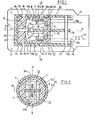
- the switch comprises two contacts 1, 2 which are both movable here. These contacts are, for example, carried by two symmetrical and parallel levers 3, 4 which are pivoted at 5, 6 in a chamber 8 belonging to a fixed insulating support part 7 and which are subjected to the action of springs represented schematically by 9, 10 so that the contact pressure is established.
- the opening means of these contacts can be of different types depending on the purpose sought for this opening; if the switch acts as a protection device against significant current overcurrents in its circuit, these levers can each be actuated by a transmission rod being connected to a pallet or a magnetizable core which is itself attracted by a coil placed in series with the contacts; if the current intensities which it is desired to interrupt reach the limit values encountered in short circuits, these levers can be actuated by the electrodynamic forces developed in these levers, on the one hand, thanks to the loop effect and, on the other hand, thanks to the known use of magnetizable parts of U-shaped attraction.
- An insulating support piece 7 comprises a base 15 which is for example integral with a shoemaker 16 of the device, and a transverse bottom 17 which is held by partitions 18, 19; a first through slot 20 of the base is aligned with a second slot 21 of the bottom in a plane PP 'which is substantially a plane of symmetry.
- the outer surface 33 of the insulating part is, for example, cylindrical, see FIG.
- first vents 32, 37 of the skirt leave the cylindrical surface 33 of the insulating part in front of which they were facing, while that second vents 34, 35 of this skirt come opposite openings such as 36a, 36b respectively leading to the chambers 8a, 8b.
- the amplitude of the repulsion forces which electrodynamically separate the contact levers during the passage of an excessive current, arriving for example by the conductors 38a, 38b connected to the line, is improved by the presence around the levers of magnetizable U-shaped structures, 39a, 39b.
- Damping means are provided between the case and the case to prevent it from rebounding at the end of the stroke, as well as reset members which restore the case to the position shown in the opposite direction to F.
- the switch operates here when an overcurrent appears in the circuit, because this first causes the separation of the contacts; as soon as this is established the arc which appears between them creates in the chamber 8 a pressure which is communicated by the second slot 21 to the space 40 located between the bottoms 17, 23 and drives the case in the direction arrow F.
- This extremely rapid movement causes the edge 41 of the screen to shear the arc against the partition 17 and simultaneously establishes total electrical isolation between the half-chambers 8a and 8b.
- the contacts can either return to the rest position and thus rest on the opposite faces of the screen, or else be kept in the open position by latches not shown or by means actuated by a mechanism linked to a magnetizable pallet or core associated with a coil 42 placed in series.
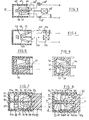
- the screen 44 or the case 45 if the latter is linked to it without play are suddenly moved either by an elastic mechanism 46 ′ previously armed and released by a core or pallet d 'a magnetic coil 43', either directly by means 43 ", 46"; in this case, the end 47 of the screen is bevelled to separate the two contacts 48, 49, and the arc which then appears causes as previously movement of the case which here adds its effects to those of the mechanism or the nucleus but after the separation of the contacts.
- the screen 44 and the case 45 can be associated with a certain axial play XX ′ so that the screen when it is moved by the means 46 first produces an initial opening of the contacts, the rapid movement for the shearing of the arc then being caused by the driving of the screen by the case.
- the case 110 and the screen 111 are linked axially and the movable contact levers 112, 113 are moved before them either simultaneously by an energy accumulator mechanism such as 115 which is triggered as before by the action of a coil 114, or simultaneously by mechanical transmission means 117 associated with this coil. It is also possible to provide a combination of these means.
- the two contacts are mobile; comparable arrangements can also be used if one of the contacts is fixed, such as the contact 50 shown in FIG. 5; in this case, the latter is not on the route followed by screen 51.
- Such an intermediate contact has the advantage of putting two arcing voltages in series.
- the screen receives a push coming from the right of the figures; in the arrangement shown in Figure 7, the screen 85 is subjected to a traction exerted on the left side of the figure, thanks to the fact that the end 86 of this screen is integral with the bottom 87 of the case 88.
- the part support 89 contacts 90, 91 here also has a bottom 92, but it has two openings 93, 94 which allow, on the one hand, the transmission of the pressure prevailing in each of the chambers 95a, 95b to the spaces 96a , 96b placed between this first bottom and the bottom 87 of the case 88 to cause displacement and, on the other hand, the emptying of the gases contained in these chambers through the orifices 97, 98 of the case.
- the screen has an opening 100 through which the movable contact (s) pass, and enters with a functional clearance in a slot 101 in the bottom 92 having the same section; thanks to lateral guides and baffles comparable to those used in FIG. 2, the screen establishes effective electrical isolation between the chambers 95a, 95b, 96a, 96b when the opening 100 is stopped in the slot 101.
- a variant of the device which has just been described and which is illustrated in FIG. 8 uses a connection of the screen and the case comparable to that illustrated previously.
- the insulating piece 62 which here receives two contact levers 63, 64 has no bottom, but has in the plane PP 'a central rib 65 which has an opening 66 inside which the two contacts 67, 68 penetrate.
- a case 69 having a bottom 70 also has a cylindrical skirt 71 which slides on the surface 62s of the part insulating; this case which comprises at least one flat screen, parallel to the longitudinal plane PP 'such as 72 which is applied to the rib 65 and has an opening 65g, may also include a second 73. This screen, or these two screens, is extend laterally to the skirt by limiting two half-chambers 74a, 74b which communicate only for the rest position of the case, see FIG.
- vents 75a, 75b establish a venting for a certain working position of the case; an orifice 77 may be disposed between the end 78 of the rib and the bottom of the case to facilitate or control the penetration of air into the space 80 when the case is expelled by the gases in the direction of the arrow F.
- the bottom of the case which may if necessary include calibrated orifices connected or not to the atmosphere to reduce the pressure , serves as a training flap for the entire case and the screen connected to it with or without axial play.
- the section of this case which for reasons of technical facilities has been illustrated by a circular shape, can also take a different outline insofar as this case as well as the contact support part can be produced by molding of suitable plastics .
Landscapes
- Arc-Extinguishing Devices That Are Switches (AREA)
- Push-Button Switches (AREA)
- Electrical Discharge Machining, Electrochemical Machining, And Combined Machining (AREA)
- Driving Mechanisms And Operating Circuits Of Arc-Extinguishing High-Tension Switches (AREA)
- Relay Circuits (AREA)
- Electrophonic Musical Instruments (AREA)
- Input Circuits Of Receivers And Coupling Of Receivers And Audio Equipment (AREA)
- Automatic Disk Changers (AREA)
- Cookers (AREA)
- Switches That Are Operated By Magnetic Or Electric Fields (AREA)
- Oscillators With Electromechanical Resonators (AREA)
- Switches With Compound Operations (AREA)
- Keying Circuit Devices (AREA)
- Distribution Board (AREA)
- Circuit Breakers (AREA)
Priority Applications (1)
| Application Number | Priority Date | Filing Date | Title |
|---|---|---|---|
| AT85402287T ATE39782T1 (de) | 1984-11-26 | 1985-11-25 | Elektrischer schalter mit schirm. |
Applications Claiming Priority (2)
| Application Number | Priority Date | Filing Date | Title |
|---|---|---|---|
| FR8417962A FR2573912B1 (fr) | 1984-11-26 | 1984-11-26 | Interrupteur electrique a ecran |
| FR8417962 | 1984-11-26 |
Publications (2)
| Publication Number | Publication Date |
|---|---|
| EP0185577A1 true EP0185577A1 (de) | 1986-06-25 |
| EP0185577B1 EP0185577B1 (de) | 1989-01-04 |
Family
ID=9309924
Family Applications (1)
| Application Number | Title | Priority Date | Filing Date |
|---|---|---|---|
| EP85402287A Expired EP0185577B1 (de) | 1984-11-26 | 1985-11-25 | Elektrischer Schalter mit Schirm |
Country Status (14)
| Country | Link |
|---|---|
| US (1) | US4677266A (de) |
| EP (1) | EP0185577B1 (de) |
| JP (1) | JPS61153908A (de) |
| AT (1) | ATE39782T1 (de) |
| BR (1) | BR8505922A (de) |
| CA (1) | CA1256918A (de) |
| CH (1) | CH664846A5 (de) |
| DE (1) | DE3541746C2 (de) |
| ES (1) | ES8609805A1 (de) |
| FR (1) | FR2573912B1 (de) |
| GB (1) | GB2169136B (de) |
| IE (1) | IE56974B1 (de) |
| IT (1) | IT1186214B (de) |
| ZA (1) | ZA859036B (de) |
Cited By (1)
| Publication number | Priority date | Publication date | Assignee | Title |
|---|---|---|---|---|
| EP0346249A1 (de) * | 1988-06-10 | 1989-12-13 | Merlin Gerin | Strombegrenzender Selbstschalter für Niederspannung mit abgedichteter Schaltkammer |
Families Citing this family (20)
| Publication number | Priority date | Publication date | Assignee | Title |
|---|---|---|---|---|
| JPH01231238A (ja) * | 1987-11-09 | 1989-09-14 | Fuji Electric Co Ltd | 回路遮断器の接触子装置 |
| CH677986A5 (de) * | 1988-07-27 | 1991-07-15 | Sprecher & Schuh Ag | |
| US5126517A (en) * | 1990-09-11 | 1992-06-30 | Square D Company | Arc suppressing current interrupter |
| US5933311A (en) * | 1998-04-02 | 1999-08-03 | Square D Company | Circuit breaker including positive temperature coefficient resistivity elements having a reduced tolerance |
| CA2266560A1 (en) * | 1997-08-25 | 1999-03-04 | Square D. Company | Current limiting circuit breakers with ptc (positive temperature coefficient resistivity) elements and arc extinguishing capabilities |
| US5886860A (en) * | 1997-08-25 | 1999-03-23 | Square D Company | Circuit breakers with PTC (Positive Temperature Coefficient resistivity |
| US6128168A (en) * | 1998-01-14 | 2000-10-03 | General Electric Company | Circuit breaker with improved arc interruption function |
| US6020802A (en) * | 1998-04-02 | 2000-02-01 | Square D Company | Circuit breaker including two magnetic coils and a positive temperature coefficient resistivity element |
| US6144540A (en) * | 1999-03-09 | 2000-11-07 | General Electric Company | Current suppressing circuit breaker unit for inductive motor protection |
| US6157286A (en) * | 1999-04-05 | 2000-12-05 | General Electric Company | High voltage current limiting device |
| DE10001632A1 (de) | 2000-01-17 | 2001-08-02 | Harting Automotive Gmbh & Co | Leitungsunterbrecher |
| US6839209B2 (en) * | 2002-06-14 | 2005-01-04 | Eaton Corporation | Shorting switch and system to eliminate arcing faults in power distribution equipment |
| EP1803137B1 (de) * | 2004-10-08 | 2012-12-05 | ABB France | Überspannungsschutzeinrichtung mit bogenschneidmitteln und entsprechendes verfahren |
| US7138597B2 (en) * | 2004-11-12 | 2006-11-21 | Eaton Corporation | Circuit breaker with arc gas propelled movable contact and opposed arc cutoff shutters |
| DE102007049166A1 (de) * | 2007-10-13 | 2009-04-16 | GM Global Technology Operations, Inc., Detroit | Elektrischer Schalter |
| CN104022000B (zh) * | 2014-05-27 | 2017-04-05 | 通能顺达科技国际有限公司 | 一种快速反应脱离断路器和断路器的快速反应脱离方法 |
| CN104022002B (zh) * | 2014-05-27 | 2015-12-02 | 通能顺达科技国际有限公司 | 一种快速切弧断路器 |
| DE102016119202B4 (de) * | 2016-10-10 | 2019-12-05 | Phoenix Contact Gmbh & Co. Kg | Überspannungsschutzelement |
| EP3561831B1 (de) * | 2018-04-24 | 2022-10-26 | ABB Schweiz AG | Elektrischer schalter |
| KR102026642B1 (ko) * | 2018-05-11 | 2019-09-30 | 엘에스산전 주식회사 | 배선용 차단기 |
Citations (5)
| Publication number | Priority date | Publication date | Assignee | Title |
|---|---|---|---|---|
| DE472305C (de) * | 1927-10-30 | 1929-02-26 | Siemens Schuckertwerke Akt Ges | Loeschkammer fuer Schalter |
| FR1238660A (fr) * | 1958-10-16 | 1960-08-12 | Siemens Ag | Dispositif pour allonger les arcs électriques |
| EP0087642A1 (de) * | 1982-02-23 | 1983-09-07 | Siemens Aktiengesellschaft | Leitungsschutzschalteranordnung, geeignet als Vorautomat |
| EP0118334A1 (de) * | 1983-02-04 | 1984-09-12 | Telemecanique | Strombegrenzender Schalter |
| EP0118333A1 (de) * | 1983-02-04 | 1984-09-12 | Telemecanique | Schalter mit einer sich beim Ausschalten zwischen den Kontakten einschiebenden Isolierstoffwand und mit Lichtbogenabquetschmittel zwischen der Isolierstoffwand und einem Isolierstoffgehäuse |
Family Cites Families (9)
| Publication number | Priority date | Publication date | Assignee | Title |
|---|---|---|---|---|
| DE591598C (de) * | 1931-08-19 | 1934-01-24 | Aeg | Elektrischer Schalter mit Lichtbogenloeschung durch ein stroemendes, gasfoermiges Medium |
| DE663263C (de) * | 1936-01-12 | 1938-08-01 | Bruno Fassmann | Vorrichtung zum Unterbrechen des Stromkreises von Widerstandsschweissmaschinen |
| BE635001A (de) * | 1962-07-16 | |||
| US3542986A (en) * | 1968-02-23 | 1970-11-24 | Gen Electric | Quick-make,quick-break actuator for high voltage electrical contacts |
| FR2339976A2 (fr) * | 1975-03-25 | 1977-08-26 | Alsthom Cgee | Cellule d'appareillage electrique a haute tension |
| DE2907691A1 (de) * | 1979-02-27 | 1980-09-04 | Siemens Ag | Druckgasschalter |
| US4342978A (en) * | 1979-03-19 | 1982-08-03 | S&C Electric Company | Explosively-actuated switch and current limiting, high voltage fuse using same |
| US4370531A (en) * | 1980-09-19 | 1983-01-25 | S&C Electric Company | Electric switch and improved device using same |
| FR2520928A1 (fr) * | 1982-02-04 | 1983-08-05 | Alsthom Atlantique | Disjoncteur a auto-soufflage pneumatique |
-
1984
- 1984-11-26 FR FR8417962A patent/FR2573912B1/fr not_active Expired
-
1985
- 1985-11-25 CH CH5011/85A patent/CH664846A5/fr not_active IP Right Cessation
- 1985-11-25 EP EP85402287A patent/EP0185577B1/de not_active Expired
- 1985-11-25 IT IT22975/85A patent/IT1186214B/it active
- 1985-11-25 CA CA000496137A patent/CA1256918A/fr not_active Expired
- 1985-11-25 US US06/802,093 patent/US4677266A/en not_active Expired - Fee Related
- 1985-11-25 AT AT85402287T patent/ATE39782T1/de active
- 1985-11-26 DE DE3541746A patent/DE3541746C2/de not_active Expired - Fee Related
- 1985-11-26 ZA ZA859036A patent/ZA859036B/xx unknown
- 1985-11-26 JP JP60265973A patent/JPS61153908A/ja active Pending
- 1985-11-26 BR BR8505922A patent/BR8505922A/pt not_active IP Right Cessation
- 1985-11-26 GB GB8529131A patent/GB2169136B/en not_active Expired
- 1985-11-26 IE IE2968/85A patent/IE56974B1/xx unknown
- 1985-11-26 ES ES549291A patent/ES8609805A1/es not_active Expired
Patent Citations (5)
| Publication number | Priority date | Publication date | Assignee | Title |
|---|---|---|---|---|
| DE472305C (de) * | 1927-10-30 | 1929-02-26 | Siemens Schuckertwerke Akt Ges | Loeschkammer fuer Schalter |
| FR1238660A (fr) * | 1958-10-16 | 1960-08-12 | Siemens Ag | Dispositif pour allonger les arcs électriques |
| EP0087642A1 (de) * | 1982-02-23 | 1983-09-07 | Siemens Aktiengesellschaft | Leitungsschutzschalteranordnung, geeignet als Vorautomat |
| EP0118334A1 (de) * | 1983-02-04 | 1984-09-12 | Telemecanique | Strombegrenzender Schalter |
| EP0118333A1 (de) * | 1983-02-04 | 1984-09-12 | Telemecanique | Schalter mit einer sich beim Ausschalten zwischen den Kontakten einschiebenden Isolierstoffwand und mit Lichtbogenabquetschmittel zwischen der Isolierstoffwand und einem Isolierstoffgehäuse |
Cited By (3)
| Publication number | Priority date | Publication date | Assignee | Title |
|---|---|---|---|---|
| EP0346249A1 (de) * | 1988-06-10 | 1989-12-13 | Merlin Gerin | Strombegrenzender Selbstschalter für Niederspannung mit abgedichteter Schaltkammer |
| FR2632771A1 (fr) * | 1988-06-10 | 1989-12-15 | Merlin Gerin | Disjoncteur limiteur basse tension a chambre de coupure etanche |
| US4943691A (en) * | 1988-06-10 | 1990-07-24 | Merlin Gerin | Low-voltage limiting circuit breaker with leaktight extinguishing chamber |
Also Published As
| Publication number | Publication date |
|---|---|
| IE56974B1 (en) | 1992-02-26 |
| FR2573912A1 (fr) | 1986-05-30 |
| IT1186214B (it) | 1987-11-18 |
| DE3541746C2 (de) | 1995-04-20 |
| GB2169136A (en) | 1986-07-02 |
| ATE39782T1 (de) | 1989-01-15 |
| DE3541746A1 (de) | 1986-05-28 |
| IE852968L (en) | 1986-05-26 |
| ES549291A0 (es) | 1986-07-16 |
| CA1256918A (fr) | 1989-07-04 |
| BR8505922A (pt) | 1986-08-19 |
| FR2573912B1 (fr) | 1987-01-09 |
| CH664846A5 (fr) | 1988-03-31 |
| US4677266A (en) | 1987-06-30 |
| GB8529131D0 (en) | 1986-01-02 |
| ES8609805A1 (es) | 1986-07-16 |
| EP0185577B1 (de) | 1989-01-04 |
| IT8522975A0 (it) | 1985-11-25 |
| ZA859036B (en) | 1986-08-27 |
| GB2169136B (en) | 1989-06-01 |
| JPS61153908A (ja) | 1986-07-12 |
Similar Documents
| Publication | Publication Date | Title |
|---|---|---|
| EP0185577B1 (de) | Elektrischer Schalter mit Schirm | |
| EP1146529B1 (de) | Pol für einen strombegrenzenden Niederspannungsleistungsschalter und damit ausgestalteter Leistungsschalter | |
| FR2540665A1 (fr) | Dispositif interrupteur muni d'un ecran isolant s'interposant entre les contacts lors de la coupure et de moyen de cisaillement de l'arc entre cet ecran et une paroi isolante | |
| FR2815461A1 (fr) | Dispositif de commutation | |
| EP0042778B1 (de) | Einpol- und Nulleiter-Kleinschalter | |
| EP0185576B1 (de) | Elektrischer Schalter mit Schirm | |
| EP0817224B1 (de) | Unterbrechungsvorrichtung für hochkalibrigen Lastschalter | |
| EP0027404B1 (de) | Elektrischer Miniaturschutzschalter mit gegossenem Gehäuse | |
| EP0261189B1 (de) | Schutzschaltergerät mit trennwand zum unterbrechen des lichtbogens | |
| EP1017074B1 (de) | Elektrisches Schaltgerät mit einem geschlitzten Kontakt | |
| FR2703821A1 (fr) | Disjoncteur électrique à répulsion électrodynamique des contacts et à chambres de coupure double. | |
| CH667942A5 (fr) | Appareil interrupteur protege contre les courants de court-circuit. | |
| FR2815463A1 (fr) | Dispositif de commutation a attenuation de chocs | |
| EP1134767B1 (de) | Magnetisch wirkende Auslösevorrichtung für einen Schutzschalter, und elektrischer Schutzapparat ausgerüstet mit einer solchen Vorrichtung | |
| EP3605581B1 (de) | Elektrisches schaltgerät mit trennbaren kontakten | |
| FR2475290A1 (fr) | Chambre de coupure de disjoncteurs basse tension a joues composites de guidage de l'arc | |
| EP0884745B1 (de) | Leistungsschalter mit einem Einschaltwiderstand | |
| EP0045672B1 (de) | Kleinschalter mit Abschaltung des Nulleiters und des Phasenleiters | |
| EP3035363B1 (de) | Lichtbogen-schaltkammer für einen leistungsschalter, und leistungsschalter, der eine solche kammer umfasst | |
| EP0905735B1 (de) | Schutzschalter mit elektromagnetischen Auslöser mit Antrieb für einen beweglichen und gabelförmigen Kontakt | |
| EP0693765B1 (de) | Elektromagnetischer Auslöser für einen Niederspannungsschutzschalter | |
| EP0118334A1 (de) | Strombegrenzender Schalter | |
| FR2511542A1 (fr) | Dispositif de liberation des contacts mobiles de contacteurs aptes a limiter les courants de courts-circuits | |
| EP0580515B1 (de) | Lastschalter mit zwei konzentrischen Löschkammern | |
| EP2619783B1 (de) | Schutzschalter mit einer vorrichtung für den einsatz eines resistors in eine stromleitung |
Legal Events
| Date | Code | Title | Description |
|---|---|---|---|
| PUAI | Public reference made under article 153(3) epc to a published international application that has entered the european phase |
Free format text: ORIGINAL CODE: 0009012 |
|
| 17P | Request for examination filed |
Effective date: 19851128 |
|
| AK | Designated contracting states |
Kind code of ref document: A1 Designated state(s): AT BE LU NL SE |
|
| 17Q | First examination report despatched |
Effective date: 19880519 |
|
| GRAA | (expected) grant |
Free format text: ORIGINAL CODE: 0009210 |
|
| AK | Designated contracting states |
Kind code of ref document: B1 Designated state(s): AT BE LU NL SE |
|
| REF | Corresponds to: |
Ref document number: 39782 Country of ref document: AT Date of ref document: 19890115 Kind code of ref document: T |
|
| PLBI | Opposition filed |
Free format text: ORIGINAL CODE: 0009260 |
|
| 26 | Opposition filed |
Opponent name: SACHSENWERK AKTIENGESELLSCHAFT Effective date: 19890921 |
|
| NLR1 | Nl: opposition has been filed with the epo |
Opponent name: SACHSENWERK AKTIENGESELLSCHAFT. |
|
| PGFP | Annual fee paid to national office [announced via postgrant information from national office to epo] |
Ref country code: AT Payment date: 19911018 Year of fee payment: 7 |
|
| PGFP | Annual fee paid to national office [announced via postgrant information from national office to epo] |
Ref country code: LU Payment date: 19911118 Year of fee payment: 7 |
|
| PGFP | Annual fee paid to national office [announced via postgrant information from national office to epo] |
Ref country code: NL Payment date: 19911130 Year of fee payment: 7 |
|
| PGFP | Annual fee paid to national office [announced via postgrant information from national office to epo] |
Ref country code: BE Payment date: 19911217 Year of fee payment: 7 |
|
| EPTA | Lu: last paid annual fee | ||
| PLAB | Opposition data, opponent's data or that of the opponent's representative modified |
Free format text: ORIGINAL CODE: 0009299OPPO |
|
| R26 | Opposition filed (corrected) |
Opponent name: AEG SACHSENWERK GMBH Effective date: 19890921 |
|
| NLXE | Nl: other communications concerning ep-patents (part 3 heading xe) |
Free format text: IN PAT.BUL.02/90,CORR.:AEG SACHSENWERK GMBH |
|
| PG25 | Lapsed in a contracting state [announced via postgrant information from national office to epo] |
Ref country code: LU Free format text: LAPSE BECAUSE OF NON-PAYMENT OF DUE FEES Effective date: 19921125 Ref country code: AT Effective date: 19921125 |
|
| PLBN | Opposition rejected |
Free format text: ORIGINAL CODE: 0009273 |
|
| STAA | Information on the status of an ep patent application or granted ep patent |
Free format text: STATUS: OPPOSITION REJECTED |
|
| PG25 | Lapsed in a contracting state [announced via postgrant information from national office to epo] |
Ref country code: BE Effective date: 19921130 |
|
| 27O | Opposition rejected |
Effective date: 19920814 |
|
| NLR2 | Nl: decision of opposition | ||
| BERE | Be: lapsed |
Owner name: LA TELEMECANIQUE ELECTRIQUE Effective date: 19921130 |
|
| PG25 | Lapsed in a contracting state [announced via postgrant information from national office to epo] |
Ref country code: NL Effective date: 19930601 |
|
| NLV4 | Nl: lapsed or anulled due to non-payment of the annual fee | ||
| EAL | Se: european patent in force in sweden |
Ref document number: 85402287.8 |
|
| PGFP | Annual fee paid to national office [announced via postgrant information from national office to epo] |
Ref country code: SE Payment date: 19961127 Year of fee payment: 12 |
|
| PG25 | Lapsed in a contracting state [announced via postgrant information from national office to epo] |
Ref country code: SE Free format text: LAPSE BECAUSE OF NON-PAYMENT OF DUE FEES Effective date: 19971126 |
|
| EUG | Se: european patent has lapsed |
Ref document number: 85402287.8 |