EP0905735B1 - Schutzschalter mit elektromagnetischen Auslöser mit Antrieb für einen beweglichen und gabelförmigen Kontakt - Google Patents
Schutzschalter mit elektromagnetischen Auslöser mit Antrieb für einen beweglichen und gabelförmigen Kontakt Download PDFInfo
- Publication number
- EP0905735B1 EP0905735B1 EP19980410097 EP98410097A EP0905735B1 EP 0905735 B1 EP0905735 B1 EP 0905735B1 EP 19980410097 EP19980410097 EP 19980410097 EP 98410097 A EP98410097 A EP 98410097A EP 0905735 B1 EP0905735 B1 EP 0905735B1
- Authority
- EP
- European Patent Office
- Prior art keywords
- circuit breaker
- magnetic circuit
- movable contact
- gap
- branches
- Prior art date
- Legal status (The legal status is an assumption and is not a legal conclusion. Google has not performed a legal analysis and makes no representation as to the accuracy of the status listed.)
- Expired - Lifetime
Links
Images


Classifications
-
- H—ELECTRICITY
- H01—ELECTRIC ELEMENTS
- H01H—ELECTRIC SWITCHES; RELAYS; SELECTORS; EMERGENCY PROTECTIVE DEVICES
- H01H71/00—Details of the protective switches or relays covered by groups H01H73/00 - H01H83/00
- H01H71/10—Operating or release mechanisms
- H01H71/12—Automatic release mechanisms with or without manual release
- H01H71/24—Electromagnetic mechanisms
- H01H71/2418—Electromagnetic mechanisms combined with an electrodynamic current limiting mechanism
-
- H—ELECTRICITY
- H01—ELECTRIC ELEMENTS
- H01H—ELECTRIC SWITCHES; RELAYS; SELECTORS; EMERGENCY PROTECTIVE DEVICES
- H01H71/00—Details of the protective switches or relays covered by groups H01H73/00 - H01H83/00
- H01H71/10—Operating or release mechanisms
- H01H71/12—Automatic release mechanisms with or without manual release
- H01H71/24—Electromagnetic mechanisms
- H01H71/2472—Electromagnetic mechanisms with rotatable armatures
Definitions
- Document FR-A-2495826 which is considered to be the closest state of the art relates to a known circuit breaker of the kind mentioned, in which the two breaking chambers are separated from one another by a partition insulating.
- the electromagnetic trip unit comprises an electromagnet equipped with a striker that acts directly on the fork of the movable contact to accelerate the movement of the latter to the open position.
- the striker is mechanically coupled to a movable core of the magnetic circuit of the electromagnet, and acts on the moving contact after catching a dead stroke.
- the performance of such a circuit breaker is nevertheless limited.
- the object of the invention is to provide a circuit breaker with high ratings, and high breaking capacity.
- the upper branch of the magnetic circuit is equipped with two curved extensions extending parallel in the direction of the arms of the movable contact so as to frame the two opposite slots of the lower branch.
- Such a forked contact arrangement in the first air gap makes it possible to obtain an addition of Laplace elementary forces for rapid opening when the intensity of the current in the pole exceeds a predetermined threshold.
- the two branches of the magnetic circuit are offset from each other along the axis of displacement of the moving contact to obtain an asymmetrical shift of the first air gap to prolong the effect of the forces Laplace in the sense of openness.
- the pallet of the magnetic circuit is provided with a first flat part and a second enveloping part arranged opposite the branches at the level of the second gap to adapt the slope of the applied stress curve. to the triggering member.
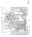
- a high-breaking miniature circuit-breaker is housed in a housing 10 made of molded insulating material, and comprises, by pole, a movable contact 12 in the form of a fork cooperating with two fixed contacts 14, 16 to constitute a contact bridge with two cut-off intervals connected in series.
- the movable contact 12 fork is actuated by a mechanism 18 for manual control by a joystick 20 and automatic via a magnetothermal trip.
- the magnetothermal trip unit comprises a thermal bimetallic trip unit (not shown), and an electromagnetic thruster 28 placed above the arc extinction chambers 24, 26.
- the electromagnetic thruster 28 comprises a magnetic circuit 30 H-shaped having a first gap 32 for housing the movable contact 12 fork, and a second air gap 34 cooperating with a pallet 36 pivoting associated with a trigger member 38.
- the circuit magnetic 30 has two branches lateral 37, 39 joined by a central branch 41 on which is wound an excitation coil 40 traversed by the current flowing through the contacts of the pole.
- the movable contact 12 has a common support arm 12A of insulating material extending vertically in a central slot 42, provided at the upper part of the first gap 32, and a conductive fork having two arms 12B, 12C parallel connected to a horizontal core 44.
- Each arm 12B, 12C extends in the vertical direction inside a slot 46, 48 provided at the lower part of the first air gap 32, and cooperates with a fixed contact 14, 16 through which the current passes through opposite directions.
- the two slots 46, 48 are arranged in the lower branch 39 of the magnetic circuit 30 extending symmetrically with respect to the central slot 42 of the upper branch 37.
- the conductive core 44 extends in the intermediate horizontal slot of the gap 32, and is located between the two branches 37, 39 being traversed unidirectionally by the total current.
- the two branches 37, 39 of the magnetic circuit 30 are magnetized in opposite polarities.
- the magnetic field lines have the same direction in the horizontal slot of the gap 32 and act on the current in the core 44, so as to generate Laplace forces for propelling the movable contact 12 to the open position when the intensity of the current exceeds a predetermined threshold.
- the other two slots 46, 48 are advantageously framed laterally by extensions 50, 52 bent over the upper branch 37 of the magnetic circuit 30.
- the magnetic fields in the two slots 46, 48 are in opposite directions, and act on opposite currents in the arms 12B, 12C of the fork of the movable contact 12, so as to add the Laplace forces in the direction of the opening.
- the presence of the extensions 50, 52 also favors the magnetic blowing of the arc pulled between each fixed contact 14, 16 and the corresponding arm 12B, 12C of the movable contact 12, and driven towards the extinction chamber 24, 26 associated .
- the series connection of the two cutoff intervals, and the addition of the Laplace elementary forces in the first air gap 32 allow to obtain a high breaking capacity, and a fast extinction of the arcs.
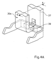
- the two branches 38, 39 of a magnetic circuit 30A of the electromagnetic trip unit are shifted in the axis of displacement of the movable contact 12, so as to obtain an asymmetrical shift of the first gap 32.
- magnetic flux passing through the latter acts on the movable contact 12 over a greater length, so as to prolong the effect of the Laplace force in the direction of opening.
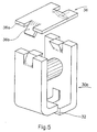
- the magnetic circuit 30B in H of the electromagnetic release comprises in the second gap 34 a pivoting pallet 36 composed of a first flat portion 36A and a second enveloping portion 36B.
- the distribution of the surfaces between the two parts 36A, 36B makes it possible to precisely adjust the slope of response of the stress curve acting on the release member 38 of FIG. 1.
- the size of the first flat portion 36A is increased relative to the second enveloping portion 36B.
- the relative width of the first flat portion 36A will be smaller relative to the second wrapping portion 36B.
Landscapes
- Physics & Mathematics (AREA)
- Electromagnetism (AREA)
- Arc-Extinguishing Devices That Are Switches (AREA)
- Breakers (AREA)
Claims (6)
- Leistungsschalter mit hohem Ausschaltvermögen, der in einem Isolierstoffgehäuse (10) angeordnet ist und pro Pol- zwei im unteren Teil des Gehäuses (10) nebeneinander angeordnete Lichtbogenlöschkammem (24, 26) mit je einem Löschblechpaket,- ein feststehendes Kontaktpaar (14, 16), das den genannten Lichtbogenlöschkammern gegenüberliegt und mit einem gabelförmigen beweglichen Doppelkontakt (12) zusammenwirkt, derart dass zwei elektrisch in Reihe geschaltete Trennstrecken gebildet werden,- sowie einen Antriebsmechanismus (18) zur Handbetätigung über einen Schaltknebel (20) und/oder zur automatischen Betätigung über Auslösemittel umfasst, die auf den über den Pol fließenden Strom ansprechen, wobei die genannten Mittel mindestens einen elektromagnetischen Auslöser mit einem Triebsystem (28) umfassen, das einen mit einem Anker (36) zusammenwirkenden Magnetkreis (30, 30A, 30B) umfasst,dadurch gekennzeichnet, dass
der gabelförmige bewegliche Kontakt (12) in einem ersten Luftspalt (32) des H-förmig ausgebildeten Magnetkreises (30) angeordnet ist, welcher zwei Seitenschenkel (37, 39) umfasst, die durch eine auf einem Mittelschenkel (41) gelagerte Erregerspule (40) mit entgegengesetzter Polarität magnetisiert werden, wobei die leitende Gabel an einem Isolierstoffstützarm (12A) befestigt ist und zwei parallel zueinander angeordnete, mit einem waagerechten Mittelsteg (44) verbundene Arme (12B, 12C) umfasst,- dass der erste Luftspalt (32) einen im oberen Schenkel (37) ausgebildeten Mittelschlitz (42) zur Durchführung des Isolierstoffstützarms (12A) sowie zwei weitere Schlitze (46, 48) umfasst, die zur Durchführung der beiden Arme (12B, 12C) des beweglichen Kontakts (12) an den seitlichen Enden des unteren Schenkels (39) des Magnetkreises (30) ausgebildet sind,und dass der Mittelsteg (44) der Gabel den zwischen den beiden Schenkeln (37, 39) ausgebildeten waagerechten Schlitz des Luftspalts (32) durchragt und durch ein von der Spule (40) erzeugtes, in einer Richtung wirkendes Magnetfeld beaufschlagt wird. - Leistungsschalter nach Anspruch 1, dadurch gekennzeichnet, dass am oberen Schenkel (37) des Magnetkreises (30) zwei umbogene Fortsätze (50, 52) ausgebildet sind, die in Richtung der Arme (12B, 12C) des beweglichen Kontakts (21) parallel zueinander verlaufen, so dass sie die beiden einander gegenüberliegenden Schlitze (46, 48) des unteren Schenkels (39) begrenzen.
- Leistungsschalter nach Anspruch 1 oder 2, dadurch gekennzeichnet, dass die beiden Schlitze (46, 48) des unteren Schenkels (39) symmetrisch zu der Mittelachse angeordnet sind, die durch den im oberen Schenkel (37) ausgebildeten Mittelschlitz (42) verläuft.
- Leistungsschalter nach Anspruch 1, dadurch gekennzeichnet, dass die beiden Schenkel (37, 39) des Magnetkreises (30A) bezüglich der Bewegungsachse des beweglichen Kontakts (12) versetzt zueinander angeordnet sind, um eine asymmetrische Verschiebung der ersten Luftspalts (32) zu erreichen und so die Wirkdauer der Laplaceschen Kräfte in Ausschaltrichtung zu verlängern.
- Leistungsschalter nach Anspruch 1, dadurch gekennzeichnet, dass der Anker (36) des Magnetkreises (30B) einen ersten flachen Bereich (36A) und einen zweiten umgreifenden Bereich (36B) aufweist, die in Höhe des zweiten Luftspalts (34) gegenüber den Schenkeln (37, 39) angeordnet sind und mit denen die Steigung der Kennlinie der auf ein Auslöseglied (38) wirkenden Kraft angepasst werden kann.
- Leistungsschalter nach Anspruch 5, dadurch gekennzeichnet, dass das Auslöseglied (38) als mit dem Anker (36) verbundene Stange ausgebildet ist, die längs des oberen Schenkels (37) des Magnetkreises (30, 30A, 30B) verläuft.
Applications Claiming Priority (2)
| Application Number | Priority Date | Filing Date | Title |
|---|---|---|---|
| FR9712091 | 1997-09-24 | ||
| FR9712091A FR2768856B1 (fr) | 1997-09-24 | 1997-09-24 | Disjoncteur a declencheur electromagnetique a propulseur d'un contact mobile a fourche |
Publications (2)
| Publication Number | Publication Date |
|---|---|
| EP0905735A1 EP0905735A1 (de) | 1999-03-31 |
| EP0905735B1 true EP0905735B1 (de) | 2006-04-12 |
Family
ID=9511587
Family Applications (1)
| Application Number | Title | Priority Date | Filing Date |
|---|---|---|---|
| EP19980410097 Expired - Lifetime EP0905735B1 (de) | 1997-09-24 | 1998-09-04 | Schutzschalter mit elektromagnetischen Auslöser mit Antrieb für einen beweglichen und gabelförmigen Kontakt |
Country Status (4)
| Country | Link |
|---|---|
| EP (1) | EP0905735B1 (de) |
| DE (1) | DE69834159T2 (de) |
| ES (1) | ES2259451T3 (de) |
| FR (1) | FR2768856B1 (de) |
Families Citing this family (2)
| Publication number | Priority date | Publication date | Assignee | Title |
|---|---|---|---|---|
| DE102011008832A1 (de) * | 2011-01-19 | 2012-07-19 | Abb Ag | Installationsschaltgerät |
| CN108321058A (zh) * | 2018-02-28 | 2018-07-24 | 首瑞(天津)电气设备有限公司 | 一种电磁脱扣断路器 |
Family Cites Families (6)
| Publication number | Priority date | Publication date | Assignee | Title |
|---|---|---|---|---|
| FR2495826A1 (fr) * | 1980-12-09 | 1982-06-11 | Merlin Gerin | Disjoncteur miniature a haut pouvoir de coupure |
| US4656446A (en) * | 1985-12-17 | 1987-04-07 | Westinghouse Electric Corp. | Current limiting circuit breaker with series double break contact system per pole |
| FR2708140B1 (fr) * | 1993-07-19 | 1995-09-01 | Merlin Gerin | Disjoncteur pourvu d'un mécanisme de commande à accrochage pilote par un propulseur électromagnétique. |
| FR2722609B1 (fr) * | 1994-07-18 | 1996-08-30 | Schneider Electric Sa | Disjoncteur electrique a actionneur electromagnetique pour calibres eleves |
| FR2722608B1 (fr) * | 1994-07-18 | 1996-08-30 | Schneider Electric Sa | Propulseur electromagnetique de disjoncteur basse tension |
| DE4445419A1 (de) * | 1994-12-20 | 1996-06-27 | Abb Patent Gmbh | Elektrisches Installationsgerät, insbesondere Leitungsschutzschalter |
-
1997
- 1997-09-24 FR FR9712091A patent/FR2768856B1/fr not_active Expired - Fee Related
-
1998
- 1998-09-04 ES ES98410097T patent/ES2259451T3/es not_active Expired - Lifetime
- 1998-09-04 EP EP19980410097 patent/EP0905735B1/de not_active Expired - Lifetime
- 1998-09-04 DE DE1998634159 patent/DE69834159T2/de not_active Expired - Lifetime
Also Published As
| Publication number | Publication date |
|---|---|
| ES2259451T3 (es) | 2006-10-01 |
| EP0905735A1 (de) | 1999-03-31 |
| FR2768856B1 (fr) | 1999-11-12 |
| DE69834159T2 (de) | 2007-01-04 |
| FR2768856A1 (fr) | 1999-03-26 |
| DE69834159D1 (de) | 2006-05-24 |
Similar Documents
| Publication | Publication Date | Title |
|---|---|---|
| EP0619593B1 (de) | Mehrpoliger Strombegrenzungsschalter mit elektrodynamischer Abstossung | |
| EP0560696B1 (de) | Kontakt für Lastschalter mit gegossenem Gehäuse | |
| EP0281443B1 (de) | Fernbetätigter Ein-/Aus-Schutzschalter | |
| EP0042778B1 (de) | Einpol- und Nulleiter-Kleinschalter | |
| EP0185577B1 (de) | Elektrischer Schalter mit Schirm | |
| EP0013642B1 (de) | Strombegrenzender Selbstschalter für Niederspannung | |
| CA1256919A (fr) | Interrupteur electrique a ecran | |
| EP0306382A1 (de) | Schalteranordnung für elektrische mehrpolige Schutzschalter mit mehreren Kontakten | |
| EP0905735B1 (de) | Schutzschalter mit elektromagnetischen Auslöser mit Antrieb für einen beweglichen und gabelförmigen Kontakt | |
| EP0649155B1 (de) | Doppelte Lichtbogenlaufschiene für die Lichtbogenleitkammer eines Schutzschalters | |
| EP0619592B1 (de) | Elektrischer Schutzschalter mit elektrodynamischer Kontaktabstossung und mit Doppellöschkammern | |
| EP0537090B1 (de) | Elektrischer Schützschalter mit Einfügung von zusätzlichen Windungen im Magnetauslöser | |
| FR2595865A1 (fr) | Interrupteur electrique, plus particulierement son actionneur magnetique de contact a haute vitesse | |
| EP0004801B1 (de) | Schalter mit einer elektromagnetischen Einrichtung zur schnellen Öffnung des beweglichen Kontaktes | |
| FR2818003A1 (fr) | Dispositif de commutation comportant un contact rotatif monte flottant et a double coupure | |
| EP0027404A1 (de) | Elektrischer Miniaturschutzschalter mit gegossenem Gehäuse | |
| EP0505292B1 (de) | Phasen- und Nulleiter-Leitungsschutzschalter mit reduziertem Platzbedarf | |
| EP0232637B1 (de) | Elektrischer Kleinschalter mit Mehrfachkontakt | |
| EP0657907B1 (de) | Stromunterbrechungsteil eines Schaltgerätes, insbesonders eines Schützes oder eines Schutzschalters | |
| EP0926693B1 (de) | Selektiver Auslöser für Leistungsschalter | |
| EP0403329A1 (de) | Schalter mit automatischer Auslösung, insbesondere Schutzschalter und Fehlerstromschutzschalter | |
| EP3699943B1 (de) | Magnetauslöser für stromunterbrechungsgerät | |
| EP0693765A1 (de) | Elektromagnetischer Auslöser für einen Niederspannungsschutzschalter | |
| EP0693764A1 (de) | Elektrischer Lastschalter mit elektromagnetischem Betätiger für Hochstrom | |
| FR2584230A1 (fr) | Chambre d'extinction d'arc pour disjoncteur a basse tension a coupure dans l'air |
Legal Events
| Date | Code | Title | Description |
|---|---|---|---|
| PUAI | Public reference made under article 153(3) epc to a published international application that has entered the european phase |
Free format text: ORIGINAL CODE: 0009012 |
|
| AK | Designated contracting states |
Kind code of ref document: A1 Designated state(s): DE ES GB IT |
|
| AX | Request for extension of the european patent |
Free format text: AL;LT;LV;MK;RO;SI |
|
| RAP1 | Party data changed (applicant data changed or rights of an application transferred) |
Owner name: SCHNEIDER ELECTRIC INDUSTRIES SA |
|
| 17P | Request for examination filed |
Effective date: 19990916 |
|
| AKX | Designation fees paid |
Free format text: DE ES GB IT |
|
| RAP1 | Party data changed (applicant data changed or rights of an application transferred) |
Owner name: SCHNEIDER ELECTRIC INDUSTRIES SA |
|
| RAP1 | Party data changed (applicant data changed or rights of an application transferred) |
Owner name: SCHNEIDER ELECTRIC INDUSTRIES SAS |
|
| GRAP | Despatch of communication of intention to grant a patent |
Free format text: ORIGINAL CODE: EPIDOSNIGR1 |
|
| GRAS | Grant fee paid |
Free format text: ORIGINAL CODE: EPIDOSNIGR3 |
|
| GRAA | (expected) grant |
Free format text: ORIGINAL CODE: 0009210 |
|
| AK | Designated contracting states |
Kind code of ref document: B1 Designated state(s): DE ES GB IT |
|
| REG | Reference to a national code |
Ref country code: GB Ref legal event code: FG4D Free format text: NOT ENGLISH |
|
| REF | Corresponds to: |
Ref document number: 69834159 Country of ref document: DE Date of ref document: 20060524 Kind code of ref document: P |
|
| GBT | Gb: translation of ep patent filed (gb section 77(6)(a)/1977) |
Effective date: 20060525 |
|
| REG | Reference to a national code |
Ref country code: ES Ref legal event code: FG2A Ref document number: 2259451 Country of ref document: ES Kind code of ref document: T3 |
|
| PLBE | No opposition filed within time limit |
Free format text: ORIGINAL CODE: 0009261 |
|
| STAA | Information on the status of an ep patent application or granted ep patent |
Free format text: STATUS: NO OPPOSITION FILED WITHIN TIME LIMIT |
|
| 26N | No opposition filed |
Effective date: 20070115 |
|
| PGFP | Annual fee paid to national office [announced via postgrant information from national office to epo] |
Ref country code: ES Payment date: 20130813 Year of fee payment: 16 |
|
| PGFP | Annual fee paid to national office [announced via postgrant information from national office to epo] |
Ref country code: DE Payment date: 20140729 Year of fee payment: 17 |
|
| REG | Reference to a national code |
Ref country code: ES Ref legal event code: FD2A Effective date: 20151026 |
|
| PGFP | Annual fee paid to national office [announced via postgrant information from national office to epo] |
Ref country code: GB Payment date: 20150902 Year of fee payment: 18 |
|
| PGFP | Annual fee paid to national office [announced via postgrant information from national office to epo] |
Ref country code: IT Payment date: 20150925 Year of fee payment: 18 |
|
| PG25 | Lapsed in a contracting state [announced via postgrant information from national office to epo] |
Ref country code: ES Free format text: LAPSE BECAUSE OF NON-PAYMENT OF DUE FEES Effective date: 20140905 |
|
| REG | Reference to a national code |
Ref country code: DE Ref legal event code: R119 Ref document number: 69834159 Country of ref document: DE |
|
| PG25 | Lapsed in a contracting state [announced via postgrant information from national office to epo] |
Ref country code: DE Free format text: LAPSE BECAUSE OF NON-PAYMENT OF DUE FEES Effective date: 20160401 |
|
| GBPC | Gb: european patent ceased through non-payment of renewal fee |
Effective date: 20160904 |
|
| PG25 | Lapsed in a contracting state [announced via postgrant information from national office to epo] |
Ref country code: GB Free format text: LAPSE BECAUSE OF NON-PAYMENT OF DUE FEES Effective date: 20160904 |
|
| PG25 | Lapsed in a contracting state [announced via postgrant information from national office to epo] |
Ref country code: IT Free format text: LAPSE BECAUSE OF NON-PAYMENT OF DUE FEES Effective date: 20160904 |