EP0693765A1 - Elektromagnetischer Auslöser für einen Niederspannungsschutzschalter - Google Patents
Elektromagnetischer Auslöser für einen Niederspannungsschutzschalter Download PDFInfo
- Publication number
- EP0693765A1 EP0693765A1 EP95410062A EP95410062A EP0693765A1 EP 0693765 A1 EP0693765 A1 EP 0693765A1 EP 95410062 A EP95410062 A EP 95410062A EP 95410062 A EP95410062 A EP 95410062A EP 0693765 A1 EP0693765 A1 EP 0693765A1
- Authority
- EP
- European Patent Office
- Prior art keywords
- pallet
- movable contact
- electromagnetic
- contact
- striker
- Prior art date
- Legal status (The legal status is an assumption and is not a legal conclusion. Google has not performed a legal analysis and makes no representation as to the accuracy of the status listed.)
- Granted
Links
Images


Classifications
-
- H—ELECTRICITY
- H01—ELECTRIC ELEMENTS
- H01H—ELECTRIC SWITCHES; RELAYS; SELECTORS; EMERGENCY PROTECTIVE DEVICES
- H01H71/00—Details of the protective switches or relays covered by groups H01H73/00 - H01H83/00
- H01H71/10—Operating or release mechanisms
- H01H71/12—Automatic release mechanisms with or without manual release
- H01H71/24—Electromagnetic mechanisms
- H01H71/2409—Electromagnetic mechanisms combined with an electromagnetic current limiting mechanism
-
- H—ELECTRICITY
- H01—ELECTRIC ELEMENTS
- H01H—ELECTRIC SWITCHES; RELAYS; SELECTORS; EMERGENCY PROTECTIVE DEVICES
- H01H71/00—Details of the protective switches or relays covered by groups H01H73/00 - H01H83/00
- H01H71/10—Operating or release mechanisms
- H01H71/12—Automatic release mechanisms with or without manual release
- H01H71/24—Electromagnetic mechanisms
- H01H71/2472—Electromagnetic mechanisms with rotatable armatures
Definitions
- the present invention relates generally to an electromagnetic booster for a low voltage circuit breaker.
- circuit breakers for example a mains voltage of 220 V and 50 Hz
- a relatively intense current for example a nominal current of 125 A
- the circuit breaker is tripped automatically, by moving a movable contact away from a fixed contact when the intensity of the electric current flowing through the circuit breaker exceeds a predetermined threshold value.
- a well-known phenomenon which is likely to affect the reliability of tripping of the circuit breaker lies in the fact that various physical or chemical phenomena can occur at the point of contact between the mobile electrical contact and the fixed electrical contact and can cause an effect of "bonding" of the electrical contacts.
- Such a known electromagnetic propellant comprises: an electromagnetic body including a core surrounded by a coil and two parallel flanks conducting the magnetic flux and each having first and second opposite ends; a pallet pivotally mounted so as to be able to assume a rest position in which it is spaced relative to said first ends of the two flanks and an actuation position in which it is magnetically attracted until it comes into contact with said first ends of the two sides; a fixed contact located in or in the vicinity of an air gap formed between said second ends of the two sides; a movable contact support arm pivotally mounted in order to move in the air gap by moving the movable contact linked to it between said rest position in which the movable contact is in contact with the fixed contact, and said position of actuation in which the movable contact is moved away from the fixed contact; and a striker consisting of an elongated piece interposed between the pallet and the mobile contact support arm.
- the pallet (v) comprises a central zone in which the electromagnetic attraction effect, one end at which a hinge (w) is arranged for rotating the pallet and another opposite end at which a striker (f) is fixed.
- a movable contact arm (d) is arranged in a substantially parallel manner and it comprises at one end a joint (p) and in the vicinity of its other opposite end a movable contact. If we consider a longitudinal median plane (25) passing through the electromagnetic body (e), we see that the articulation (p) is located opposite the articulation (w) with respect to this longitudinal median plane (25).
- the free end of the striker (f) is intended to come into contact with a central zone of the movable contact arm (d), that is to say that the striker (f) pushes the contact arm mobile (d) at a point between the joint (p) and the mobile contact.
- the striker (f) is located opposite the articulation (w) relative to this longitudinal median plane (25).
- the displacement of the striker (f) is greater than the displacement of the central zone of the pallet (v) at the level of which the effect of electromagnetic attraction takes place.
- the pallet (v) therefore constitutes a lever arm which amplifies the movement at the level of the striker (f). Consequently, the force at the striker (f) is less than the electromagnetic attraction force at the central area of the pallet (v).
- the striker (f) pushes the movable contact arm (v) in a central zone, so that the displacement at the movable contact is greater than the movement of the striker (f) because the arm of movable contact (d) behaves like a lever arm which amplifies the movement of the striker (f).
- An object of the present invention is to provide an electromagnetic thruster for a low voltage circuit breaker having greater reliability in the operation of its tripping.
- Another object of the present invention consists in proposing such an electromagnetic propellant offering greater precision of the threshold of intensity of electric current which causes its triggering.
- Another object of the present invention consists in proposing such an electromagnetic propellant which can be arranged in a more compact manner.
- an electromagnetic propellant for low voltage circuit breaker comprising: an electromagnetic body including a core surrounded by a coil and two parallel flanks conducting the magnetic flux and each having first and second ends opposite; a pallet pivotally mounted around a joint so as to be able to assume a rest position in which it is separated from said first ends of the two sides and an actuating position in which it is attracted magnetically until it comes into contact with said first ends of the two sides; a fixed contact located in or in the vicinity of an air gap formed between said second ends of the two sides; a movable contact support arm pivotally mounted around a joint in order to move in the air gap by moving the movable contact linked to it between said rest position in which the movable contact is in contact with the fixed contact and said actuating position in which the movable contact is moved away from the fixed contact; and a striker consisting of an elongated piece interposed between the pallet and the movable contact support arm; in which the articulation of
- the striker is arranged so that its longitudinal direction makes an angle of 90 ° ⁇ 30 ° with the longitudinal direction of the pallet and also makes an angle of 90 ° ⁇ 30 ° with the longitudinal direction of the movable contact arm.
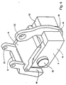
- the circuit breaker 1 comprises a housing 2 which contains a fixed contact 3, a mobile contact 4 which is mounted at the end of a mobile contact arm 5, a breaking chamber 6 and various elements of electrical connections (not shown) allowing to connect the fixed and mobile contacts to terminals (not shown). All these elements are well known in the prior art and do not require here a more detailed description.
- the object of the present invention relates more particularly to the sub-assembly of the circuit breaker which constitutes what is commonly called "an electromagnetic propellant".
- the electromagnetic thruster is used to cause the tripping of the circuit breaker, that is to say the opening of the electrical contact when the electric current intensity exceeds a predetermined threshold.
- the electromagnetic propellant is used to cause this tripping abruptly, that is to say to cause a very rapid separation of the fixed and movable contacts 3, 4.
- the electromagnetic propellant according to the present invention consists essentially of an electromagnetic body 7, a pallet 8 pivotally mounted, and a striker 9.
- the electromagnetic body 7 generally includes a core 10 of cylindrical shape surrounded by a coil (not shown) or at least one turn, and two flanks 11, 12 which are arranged parallel to each other, which extend perpendicular to the longitudinal axis of the core 10 and which are arranged substantially respectively at one and the other of the ends of the core 10.
- the sidewall 11 has a first end 13 directed towards the pallet 8 and a second opposite end 14 and in the same way the side 12 has a first end 15 directed towards the pallet 8 and a second opposite end 16.
- the first ends 13 and 15 form planar faces which are coplanar and which are directed towards the pallet 8.
- the second ends 14 and 16 form flat faces which face each other while being separated from each other by a certain distance a end of constituting between them an air gap 17.
- the pallet 8 has a flat face 18 which faces the ends 13 and 15 of the electromagnetic body 7.
- the vane 8 When the electromagnetic thruster is at rest, the vane 8 is located at a certain distance from the electromagnetic body 7, that is to say that its face 18 is located at a certain distance from the faces of the ends 13 and 15 forming thus, respectively, an air gap 19 and an air gap 20.
- a first magnetic flux is established in closed loop by successively passing through the core 10, a flank part 11, air gap 19, pallet 8, air gap 20 and part of flank 12.
- a second magnetic flux is established by successively crossing the core 10, the other part of flank 11 , the air gap 17 and the other part of the sidewall 12.
- the pallet 8 is mounted in an oscillating manner thanks to an articulation 21 and the movable contact arm 5 is also mounted in an oscillating way thanks to an articulation 22.
- the fixed contact 3 is mounted in the air gap 17 or close to it and at least a part of the movable contact arm 5 extends through the air gap 17.
- the striker 9 is in the form of an elongated part of which one end is connected via a hinge 23 to the pallet 8 and the other free end 24 of which is located near the movable contact arm 5.
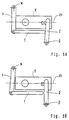
- FIG. 2A the same essential elements can be distinguished schematically as those which have been described previously. For this reason, the same reference indexes have been used in FIGS. 2A and 2B relative to FIGS. 3 to 6 of the particular embodiment, this in order to facilitate understanding of the operation of the device.
- a dashed line 25 shows the trace of a longitudinal median plane of the electromagnetic body 7. This median plane 25 is oriented so as to correspond to a plane including the loops of the magnetic fluxes which have been described previously. (The same median plane 25 has been similarly reported in FIGS.
- FIG. 2A it can be seen that the articulation 21 of the pallet 8 is located at a certain distance from the plane 25 and that the articulation 22 of the movable contact arm 5 is located at another distance from the plane 25 but on the same side than that of articulation 21 with respect to this plane 25.
- the articulation 21 of the pallet 8 and the articulation 22 of the movable contact arm 5 are located on the same side relative to the electromagnetic body 7.
- the surface 18 of the pallet 8 which faces the surfaces 13 and 15 of the ends of the sides 11 and 12 of the electromagnetic body 7 is a surface which is located in an end region 26 of the pallet 8.
- the articulation 23 which connects the striker 9 to the pallet 8 is located in a central zone of the pallet 8, that is to say is situated between the end zone 26 and the articulation 21.
- the free end 24 of the striker 9 is located near the movable contact arm 5 so as to bear against this movable contact arm 5 at a contact point 27 located in a central zone of the movable contact arm 5, that is to say in a area located between a free end 28 of the movable contact arm 5 which supports the movable contact 4 and the articulation 22 of the movable contact arm 5.
- the striker 9 is arranged so that its longitudinal direction is substantially perpendicular to the longitudinal direction of the pallet 8 and also substantially perpendicular to the longitudinal direction of the contact arm mobile 5.
- substantially perpendicular is used here to designate an angle between 60 and 120 °, that is to say an angle of 90 ° ⁇ 30 °.
- the general shape as seen from the side of the assembly constituted by the pallet 8, the striker 9 and the movable contact arm 5 is a shape which resembles that of an H.
- the electromagnetic striker When a current flowing in the coil which surrounds the core 10 is less than a predetermined threshold value, the electromagnetic striker remains in a quiescent condition as shown in FIG. 2A, that is to say a condition in which the pallet 8 is separated from the electromagnetic body 7 and in which simultaneously the movable contact arm 5 is brought closer to the electromagnetic body 7 so that the movable contact 4 is in contact with the fixed contact 3.
- an elastic means (not shown) which permanently pushes the pallet 8 in a direction which moves the end part 26 of the pallet 8 away from the electromagnetic body 7, that is to say in a direction which moves the face 18 away from the faces 13 and 15 to delimit said air gap 19, 20.
- the attractive force which is exerted between the pallet 8 and the electromagnetic body 7 exceeds the elastic pushing force of the elastic means and it follows that the pallet 8 abruptly approaches the electromagnetic body 7 and this pivoting movement causes the striker 9 to move, including the end 24 comes to bear on the movable contact arm 5, then pushes this movable contact arm 5 so as to rotate it to bring it into a condition in which the movable contact 4 is moved away from the fixed contact 3.
- the electromagnetic striker is then brought into a tripping condition as shown in FIG. 2B. In the rest condition shown in FIG. 2A, it can be seen that a slight space is provided between the end 24 of the striker 9 and the contact zone 27 of the movable contact arm 5.
Landscapes
- Physics & Mathematics (AREA)
- Electromagnetism (AREA)
- Breakers (AREA)
- Driving Mechanisms And Operating Circuits Of Arc-Extinguishing High-Tension Switches (AREA)
- Emergency Protection Circuit Devices (AREA)
- Arc-Extinguishing Devices That Are Switches (AREA)
- Mechanisms For Operating Contacts (AREA)
- Elimination Of Static Electricity (AREA)
- Relay Circuits (AREA)
Applications Claiming Priority (2)
| Application Number | Priority Date | Filing Date | Title |
|---|---|---|---|
| FR9409066 | 1994-07-18 | ||
| FR9409066A FR2722608B1 (fr) | 1994-07-18 | 1994-07-18 | Propulseur electromagnetique de disjoncteur basse tension |
Publications (2)
| Publication Number | Publication Date |
|---|---|
| EP0693765A1 true EP0693765A1 (de) | 1996-01-24 |
| EP0693765B1 EP0693765B1 (de) | 1999-03-24 |
Family
ID=9465632
Family Applications (1)
| Application Number | Title | Priority Date | Filing Date |
|---|---|---|---|
| EP95410062A Expired - Lifetime EP0693765B1 (de) | 1994-07-18 | 1995-07-06 | Elektromagnetischer Auslöser für einen Niederspannungsschutzschalter |
Country Status (12)
| Country | Link |
|---|---|
| EP (1) | EP0693765B1 (de) |
| CN (1) | CN1052336C (de) |
| AT (1) | ATE178161T1 (de) |
| AU (1) | AU686809B2 (de) |
| BR (1) | BR9503348A (de) |
| DE (1) | DE69508483T2 (de) |
| ES (1) | ES2130553T3 (de) |
| FR (1) | FR2722608B1 (de) |
| HU (1) | HU217402B (de) |
| RU (1) | RU2144234C1 (de) |
| TR (1) | TR199500863A2 (de) |
| ZA (1) | ZA955705B (de) |
Cited By (3)
| Publication number | Priority date | Publication date | Assignee | Title |
|---|---|---|---|---|
| EP0794547A1 (de) * | 1996-03-08 | 1997-09-10 | Schneider Electric Sa | Elektrischer Schutzschalter mit elektromagnetischen Betätiger und Betätigungsmechanismus |
| FR2768856A1 (fr) * | 1997-09-24 | 1999-03-26 | Schneider Electric Sa | Disjoncteur a declencheur electromagnetique a propulseur d'un contact mobile a fourche |
| EP1376639A1 (de) * | 2002-06-17 | 2004-01-02 | Hager Electro S.A. | Elektromagnetischer Auslöser mit linear bewegtem Tauchkolben |
Families Citing this family (1)
| Publication number | Priority date | Publication date | Assignee | Title |
|---|---|---|---|---|
| JP6752351B2 (ja) * | 2016-08-30 | 2020-09-09 | 趙建平ZHAO, Jianping | 遮断器ブラケット |
Citations (3)
| Publication number | Priority date | Publication date | Assignee | Title |
|---|---|---|---|---|
| DE942455C (de) | 1941-07-12 | 1956-05-03 | Aeg | Elektrischer UEberstromselbstschalter fuer Wechselstrom |
| DE2945618A1 (de) * | 1979-10-23 | 1981-05-07 | BBC AG Brown, Boveri & Cie., Baden, Aargau | Verfahren zum oeffnen eines ueberstromschalters sowie ueberstromschalters sowie ueberstromschalter zur ausfuehrung des verfahrens |
| EP0410257A1 (de) | 1989-07-26 | 1991-01-30 | Siemens Aktiengesellschaft | Elektromechanischer Schnellschalter |
-
1994
- 1994-07-18 FR FR9409066A patent/FR2722608B1/fr not_active Expired - Fee Related
-
1995
- 1995-07-06 EP EP95410062A patent/EP0693765B1/de not_active Expired - Lifetime
- 1995-07-06 DE DE69508483T patent/DE69508483T2/de not_active Expired - Fee Related
- 1995-07-06 AT AT95410062T patent/ATE178161T1/de active
- 1995-07-06 ES ES95410062T patent/ES2130553T3/es not_active Expired - Lifetime
- 1995-07-10 ZA ZA955705A patent/ZA955705B/xx unknown
- 1995-07-12 HU HU9502110A patent/HU217402B/hu not_active IP Right Cessation
- 1995-07-14 AU AU25013/95A patent/AU686809B2/en not_active Ceased
- 1995-07-17 TR TR95/00863A patent/TR199500863A2/xx unknown
- 1995-07-17 RU RU95113143A patent/RU2144234C1/ru not_active IP Right Cessation
- 1995-07-17 BR BR9503348A patent/BR9503348A/pt not_active IP Right Cessation
- 1995-07-18 CN CN95108438A patent/CN1052336C/zh not_active Expired - Fee Related
Patent Citations (3)
| Publication number | Priority date | Publication date | Assignee | Title |
|---|---|---|---|---|
| DE942455C (de) | 1941-07-12 | 1956-05-03 | Aeg | Elektrischer UEberstromselbstschalter fuer Wechselstrom |
| DE2945618A1 (de) * | 1979-10-23 | 1981-05-07 | BBC AG Brown, Boveri & Cie., Baden, Aargau | Verfahren zum oeffnen eines ueberstromschalters sowie ueberstromschalters sowie ueberstromschalter zur ausfuehrung des verfahrens |
| EP0410257A1 (de) | 1989-07-26 | 1991-01-30 | Siemens Aktiengesellschaft | Elektromechanischer Schnellschalter |
Cited By (5)
| Publication number | Priority date | Publication date | Assignee | Title |
|---|---|---|---|---|
| EP0794547A1 (de) * | 1996-03-08 | 1997-09-10 | Schneider Electric Sa | Elektrischer Schutzschalter mit elektromagnetischen Betätiger und Betätigungsmechanismus |
| FR2745949A1 (fr) * | 1996-03-08 | 1997-09-12 | Schneider Electric Sa | Disjoncteur electrique a actionneur electromagnetique et mecanisme de commande |
| FR2768856A1 (fr) * | 1997-09-24 | 1999-03-26 | Schneider Electric Sa | Disjoncteur a declencheur electromagnetique a propulseur d'un contact mobile a fourche |
| EP0905735A1 (de) * | 1997-09-24 | 1999-03-31 | Schneider Electric Sa | Schutzschalter mit elektromagnetischen Auslöser mit Antrieb für einen beweglichen und gabelförmigen Kontakt |
| EP1376639A1 (de) * | 2002-06-17 | 2004-01-02 | Hager Electro S.A. | Elektromagnetischer Auslöser mit linear bewegtem Tauchkolben |
Also Published As
| Publication number | Publication date |
|---|---|
| DE69508483D1 (de) | 1999-04-29 |
| RU95113143A (ru) | 1997-06-27 |
| RU2144234C1 (ru) | 2000-01-10 |
| DE69508483T2 (de) | 1999-10-07 |
| FR2722608A1 (fr) | 1996-01-19 |
| CN1052336C (zh) | 2000-05-10 |
| HU9502110D0 (en) | 1995-09-28 |
| FR2722608B1 (fr) | 1996-08-30 |
| ES2130553T3 (es) | 1999-07-01 |
| HU217402B (hu) | 2000-01-28 |
| CN1124873A (zh) | 1996-06-19 |
| ZA955705B (en) | 1996-05-14 |
| HUT73306A (en) | 1996-07-29 |
| TR199500863A2 (tr) | 1996-06-21 |
| ATE178161T1 (de) | 1999-04-15 |
| EP0693765B1 (de) | 1999-03-24 |
| AU686809B2 (en) | 1998-02-12 |
| AU2501395A (en) | 1996-02-01 |
| BR9503348A (pt) | 1996-07-16 |
Similar Documents
| Publication | Publication Date | Title |
|---|---|---|
| FR2578354A1 (fr) | Disjoncteur pouvant fonctionner en interrupteur | |
| FR2815461A1 (fr) | Dispositif de commutation | |
| CA1112271A (fr) | Contacteur electro-magnetique equipe d'un electro-aimant sensible aux surintensites pour provoquer la limitation et la coupure des courants excessifs | |
| EP2466601B1 (de) | Unterbrechungsvorrichtung mit Monitor mit Lichtbogenunterbrechung | |
| FR2580426A1 (fr) | Disjoncteur pour basse tension avec fonction de commutation pour commande de systeme de gestion d'energie electrique | |
| EP1347479A1 (de) | Superschnelles strombegrenzendes elektrisches Schaltgerät | |
| FR2796202A1 (fr) | Mecanisme d'interrupteur pour disjoncteur | |
| EP0693765B1 (de) | Elektromagnetischer Auslöser für einen Niederspannungsschutzschalter | |
| EP2717284B1 (de) | Bedienungsvorrichtung eines elektrischen Schutzschaltgeräts, und diese umfassendes elektrisches Schutzschaltgerät | |
| EP0325501B1 (de) | Automatische Schalter, insbesondere Differential- und Schutzschaltern | |
| EP0130208B1 (de) | Schalter mit bedientem öffnen und schliessen und mit automatischer öffnung im fall eines überstromes | |
| FR2570869A1 (fr) | Perfectionnement aux ensembles de contact des interrupteurs a coupure | |
| EP0027404A1 (de) | Elektrischer Miniaturschutzschalter mit gegossenem Gehäuse | |
| EP0244276B1 (de) | Elektrischer Schalter für Schutzgerät, wie Schutzschalter | |
| EP0018553B1 (de) | Modulschutzschalter | |
| EP0054499B1 (de) | Schalter mit Trennung des Nulleiters | |
| CH716204B1 (fr) | Combiné disjoncteur et interrupteur sectionneur. | |
| FR2829869A1 (fr) | Appareil electrique interrupteur muni d'un dispositif de commutation de contact | |
| EP1033736A1 (de) | Magnetischer Betätiger mit Klappanker, insbesondere für einen Schutzschalter, und Schutzschalter mit einem solchen Betätiger | |
| EP0693764B1 (de) | Elektrischer Lastschalter mit elektromagnetischem Betätiger für Hochstrom | |
| EP0373018B1 (de) | Handbetätigter Mechanismus für schnelle Unterbrechung für elektrische Schalter | |
| EP0218497B1 (de) | Schutzschalter mit federnder Lasche | |
| FR3093227A1 (fr) | Dispositif de commande de contacts d’une ampoule à vide pour appareil de connexion électrique | |
| FR2559307A1 (fr) | Contact equipe d'un compensateur magnetique autoliberable a partir d'un seuil de force de compensation, et contacteur-disjoncteur utilisant un tel contact | |
| EP0905735A1 (de) | Schutzschalter mit elektromagnetischen Auslöser mit Antrieb für einen beweglichen und gabelförmigen Kontakt |
Legal Events
| Date | Code | Title | Description |
|---|---|---|---|
| PUAI | Public reference made under article 153(3) epc to a published international application that has entered the european phase |
Free format text: ORIGINAL CODE: 0009012 |
|
| AK | Designated contracting states |
Kind code of ref document: A1 Designated state(s): AT BE DE ES GB IT NL SE |
|
| 17P | Request for examination filed |
Effective date: 19960723 |
|
| GRAG | Despatch of communication of intention to grant |
Free format text: ORIGINAL CODE: EPIDOS AGRA |
|
| 17Q | First examination report despatched |
Effective date: 19980602 |
|
| GRAG | Despatch of communication of intention to grant |
Free format text: ORIGINAL CODE: EPIDOS AGRA |
|
| GRAH | Despatch of communication of intention to grant a patent |
Free format text: ORIGINAL CODE: EPIDOS IGRA |
|
| GRAH | Despatch of communication of intention to grant a patent |
Free format text: ORIGINAL CODE: EPIDOS IGRA |
|
| GRAA | (expected) grant |
Free format text: ORIGINAL CODE: 0009210 |
|
| AK | Designated contracting states |
Kind code of ref document: B1 Designated state(s): AT BE DE ES GB IT NL SE |
|
| REF | Corresponds to: |
Ref document number: 178161 Country of ref document: AT Date of ref document: 19990415 Kind code of ref document: T |
|
| REF | Corresponds to: |
Ref document number: 69508483 Country of ref document: DE Date of ref document: 19990429 |
|
| GBT | Gb: translation of ep patent filed (gb section 77(6)(a)/1977) |
Effective date: 19990507 |
|
| REG | Reference to a national code |
Ref country code: ES Ref legal event code: FG2A Ref document number: 2130553 Country of ref document: ES Kind code of ref document: T3 |
|
| PLBE | No opposition filed within time limit |
Free format text: ORIGINAL CODE: 0009261 |
|
| STAA | Information on the status of an ep patent application or granted ep patent |
Free format text: STATUS: NO OPPOSITION FILED WITHIN TIME LIMIT |
|
| 26N | No opposition filed | ||
| PGFP | Annual fee paid to national office [announced via postgrant information from national office to epo] |
Ref country code: DE Payment date: 20010609 Year of fee payment: 7 |
|
| PGFP | Annual fee paid to national office [announced via postgrant information from national office to epo] |
Ref country code: ES Payment date: 20010719 Year of fee payment: 7 |
|
| PGFP | Annual fee paid to national office [announced via postgrant information from national office to epo] |
Ref country code: BE Payment date: 20010918 Year of fee payment: 7 |
|
| REG | Reference to a national code |
Ref country code: GB Ref legal event code: IF02 |
|
| PG25 | Lapsed in a contracting state [announced via postgrant information from national office to epo] |
Ref country code: ES Free format text: LAPSE BECAUSE OF NON-PAYMENT OF DUE FEES Effective date: 20020707 |
|
| PG25 | Lapsed in a contracting state [announced via postgrant information from national office to epo] |
Ref country code: BE Free format text: LAPSE BECAUSE OF NON-PAYMENT OF DUE FEES Effective date: 20020731 |
|
| BERE | Be: lapsed |
Owner name: S.A. *SCHNEIDER ELECTRIC Effective date: 20020731 |
|
| PG25 | Lapsed in a contracting state [announced via postgrant information from national office to epo] |
Ref country code: DE Free format text: LAPSE BECAUSE OF NON-PAYMENT OF DUE FEES Effective date: 20030201 |
|
| REG | Reference to a national code |
Ref country code: ES Ref legal event code: FD2A Effective date: 20030811 |
|
| PG25 | Lapsed in a contracting state [announced via postgrant information from national office to epo] |
Ref country code: IT Free format text: LAPSE BECAUSE OF NON-PAYMENT OF DUE FEES;WARNING: LAPSES OF ITALIAN PATENTS WITH EFFECTIVE DATE BEFORE 2007 MAY HAVE OCCURRED AT ANY TIME BEFORE 2007. THE CORRECT EFFECTIVE DATE MAY BE DIFFERENT FROM THE ONE RECORDED. Effective date: 20050706 |
|
| PGFP | Annual fee paid to national office [announced via postgrant information from national office to epo] |
Ref country code: SE Payment date: 20120711 Year of fee payment: 18 Ref country code: GB Payment date: 20120704 Year of fee payment: 18 |
|
| PGFP | Annual fee paid to national office [announced via postgrant information from national office to epo] |
Ref country code: NL Payment date: 20120710 Year of fee payment: 18 |
|
| PGFP | Annual fee paid to national office [announced via postgrant information from national office to epo] |
Ref country code: AT Payment date: 20120626 Year of fee payment: 18 |
|
| REG | Reference to a national code |
Ref country code: NL Ref legal event code: V1 Effective date: 20140201 |
|
| REG | Reference to a national code |
Ref country code: SE Ref legal event code: EUG |
|
| REG | Reference to a national code |
Ref country code: AT Ref legal event code: MM01 Ref document number: 178161 Country of ref document: AT Kind code of ref document: T Effective date: 20130706 |
|
| GBPC | Gb: european patent ceased through non-payment of renewal fee |
Effective date: 20130706 |
|
| PG25 | Lapsed in a contracting state [announced via postgrant information from national office to epo] |
Ref country code: NL Free format text: LAPSE BECAUSE OF NON-PAYMENT OF DUE FEES Effective date: 20140201 Ref country code: SE Free format text: LAPSE BECAUSE OF NON-PAYMENT OF DUE FEES Effective date: 20130707 Ref country code: GB Free format text: LAPSE BECAUSE OF NON-PAYMENT OF DUE FEES Effective date: 20130706 |
|
| PG25 | Lapsed in a contracting state [announced via postgrant information from national office to epo] |
Ref country code: AT Free format text: LAPSE BECAUSE OF NON-PAYMENT OF DUE FEES Effective date: 20130706 |