EP2619783B1 - Schutzschalter mit einer vorrichtung für den einsatz eines resistors in eine stromleitung - Google Patents
Schutzschalter mit einer vorrichtung für den einsatz eines resistors in eine stromleitung Download PDFInfo
- Publication number
- EP2619783B1 EP2619783B1 EP11758468.0A EP11758468A EP2619783B1 EP 2619783 B1 EP2619783 B1 EP 2619783B1 EP 11758468 A EP11758468 A EP 11758468A EP 2619783 B1 EP2619783 B1 EP 2619783B1
- Authority
- EP
- European Patent Office
- Prior art keywords
- contact
- contacts
- breaker
- circuit
- circuit breaker
- Prior art date
- Legal status (The legal status is an assumption and is not a legal conclusion. Google has not performed a legal analysis and makes no representation as to the accuracy of the status listed.)
- Not-in-force
Links
Images


Classifications
-
- H—ELECTRICITY
- H01—ELECTRIC ELEMENTS
- H01H—ELECTRIC SWITCHES; RELAYS; SELECTORS; EMERGENCY PROTECTIVE DEVICES
- H01H33/00—High-tension or heavy-current switches with arc-extinguishing or arc-preventing means
- H01H33/02—Details
- H01H33/04—Means for extinguishing or preventing arc between current-carrying parts
- H01H33/16—Impedances connected with contacts
- H01H33/166—Impedances connected with contacts the impedance being inserted only while closing the switch
-
- H—ELECTRICITY
- H01—ELECTRIC ELEMENTS
- H01H—ELECTRIC SWITCHES; RELAYS; SELECTORS; EMERGENCY PROTECTIVE DEVICES
- H01H33/00—High-tension or heavy-current switches with arc-extinguishing or arc-preventing means
- H01H33/02—Details
- H01H2033/028—Details the cooperating contacts being both actuated simultaneously in opposite directions
Definitions
- the invention relates to a device for inserting resistance into a cut-off device, or circuit breaker, of a medium, high or very high voltage electricity transmission line comprising a double-contact interrupting chamber.
- the insertion of resistance makes it possible to limit the overvoltage effects present on the line in which the circuit breaker is installed, during a closing operation of the circuit-breaker.
- the breaking chamber comprises a movable main contact, integral with a movable arcing contact, and a semi-mobile main contact integral with a semi-moving arc contact.
- the movable contact and the semi-moving contact are connected to a linkage actuator of the cutting chamber by a drive member here consisting of a return lever which allows to have simultaneous and opposite movements of mobile and semi-mobile contacts.
- the resistor is connected in series with the interrupting chamber, and an electrical switch is connected in parallel with the resistor.
- the switch is closed or not, depending on the state of the breaking chamber, and bypassed, or not, the resistance.
- WO 93/02461 discloses a resistance insertion device in series with an interrupting chamber.
- the insertion device is arranged in line with the interrupting chamber, and an axial rod, through which the chamber of cutoff is actuated, also acts on the device of insertion of the resistance.
- the switch comprises a rocker arm which is pushed by a rod slidably mounted axially in the circuit breaker.
- the dimensions, and thus the mass of the components of the insertion device are important.
- the object of the invention is to provide a resistance inserter in series with a double-contact interrupting chamber, which makes it possible to solve these disadvantages.
- the driving of the contacts of the insertion device by the return lever of the interrupting chamber makes it possible to limit the number of components of the insertion device and to simplify the general structure of the circuit breaker.
- each contact of the insertion device is disengaged from the drive member, during the opening phase of the circuit breaker, and the insertion device comprises additional means for driving each contact during the phase. opening circuit breaker for disconnecting the contacts of the insertion device, said additional drive means being separate from the drive member.
- the additional drive means comprise elastic means for driving said at least one contact towards a position remote from the other contact of the switch.
- the insertion device is of the double contact movement type and the two contacts of the insertion device are movable relative to each other in opposite and simultaneous movements.
- the resistor is connected in series with the interrupting chamber
- the insertion device is connected in parallel with the resistor and is made in such a way that the contacts of the insertion device are brought into contact after closure. of the interrupting chamber during a closing phase of the circuit breaker, and in such a way that the contacts of the insertion device are disconnected after the opening of the interrupting chamber during an opening phase of the circuit breaker.
- the insertion device comprises a pusher associated with each contact which is connected to the drive member and one end of the pusher bears against a bearing portion of the associated contact, in a direction corresponding to the direction moving the contact towards the other contact.
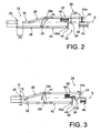
- figure 1 a circuit breaker 10 for a medium, high or very high voltage electricity transmission line.
- the circuit breaker 10 here comprises a switching chamber 12 of the double-contact type which is arranged inside a casing 14 made of insulating material, for example ceramic, which is mounted on a support 16.
- the breaking chamber 12 comprises a movable contact 18, integral with a movable arcing contact, a blowing cylinder and a blowing nozzle (not shown) and comprises a semi-moving contact 20, integral with a semi-moving arc contact (not shown).
- the movable contact 18 and the semi-moving contact 20 are here movable along the main axis A of the breaking chamber 12 in opposite directions.
- the moving contact 18 and the semi-moving contact 20 are driven by a control mechanism (not shown) comprising an operating rod 22 ( figure 1 ) which is coaxial with the breaking chamber 12 and which is movable axially slidably in the interrupting chamber.
- the operating rod 22 drives a drive member 24 of the movable contact 18 and the semi-moving contact 20.
- the drive member 24 consists of a return lever 24 which is pivotally mounted in the breaking chamber 12 about an axis perpendicular to the plane of the figures. It will be understood that the invention is not limited to this embodiment of the drive member 24, which may also consist of a cam, a roller or a rack, which is made to cause the contacts.
- the lever 24 is connected to the operating rod 22 by means not shown, so that a sliding of the rod 22 causes the pivoting of the lever 24 in one direction or the other.
- the movable contact 18 and the semi-moving contact 20 are connected to the return lever 24 so that the moving contact 18 and the semi-moving contact 20 move simultaneously and in opposite directions during the rotation of the lever 24.
- Displacements in opposite directions of the moving contact 18 and the semi-moving contact 20 have the main advantage of having a relative speed of the moving contact 18 relative to the relatively high semi-moving contact 20, while the speed of the moving contact 18 and semi-moving contact 20 in the interrupting chamber 12 is less.
- the lever 24 consists of an oblong element, the long length of which is mainly vertical with reference to the figures, that is to say transverse to the main axis of the breaking chamber 12.
- the lever 24 is pivotally mounted at its center in the interrupting chamber 12, and each upper end 24s or lower 24i of the lever 24 is connected to the moving contact 18 or to the semi-moving contact 20 via a connecting rod 26.
- the lever 24 pivots under the action of the operating rod 22, here in the counterclockwise direction, so that it pushes the movable contact 18 axially towards the semi contact -mobile 20, here to the left, and simultaneously, the lever 24 axially pulls the semi-moving contact 20 to the movable contact 18, here to the right through the connecting rods 26.
- the movable contact 18 and the semi-moving contact 20 are in contact with each other, so that the interrupting chamber 12 is closed.
- the lever 24 pivots clockwise under the action of the operating rod 22, so that the lever 24 axially pulls the movable contact 18 away from the semi-moving contact 20, here to the right and simultaneously, the lever 24 axially pushes the semi-moving contact 20 away from the movable contact 18, here to the left.
- the breaking chamber 12 has returned to its configuration shown in FIG. figure 2 , for which the movable contact 18 and the semi-moving contact 20 are spaced from each other, so that the interrupting chamber 12 is open.
- the circuit breaker 10 also comprises a device 28 for inserting a resistor in series with the breaking chamber 12.
- the insertion device 28 makes it possible to limit the overvoltage effects present on the line on which the circuit breaker 10 is installed during the closing of the breaking chamber 12.
- the resistor is connected in series with the interrupting chamber 12, i.e. one terminal of the resistor is connected to one terminal of the interrupting chamber, and the other terminal of the resistor is connected. to a driver (not shown) of the power line.
- the insertion device 28 also comprises a switch 32 which is connected in parallel with the resistor, and which is able to be closed in order to short-circuit the resistor, so that the current flowing through the current line does not circulate in the circuit. resistance.
- the switch 32 comprises two contacts 36, 38 which are able to be brought into electrical contact with each other when the switch 32 is closed, thereby putting the resistor in short circuit.
- the insertion device 28 is of the type with double movement of the contacts.
- the two contacts 36, 38 of the switch 32 are movable in the insertion device 28 and they are able to move relative to each other along the main axis A of the breaking chamber 12, to get closer or for away, similarly to the displacements of the movable contact 18 and the semi-moving contact 20 of the breaking chamber 12.
- the two contacts 36, 38 of the switch 32 are connected to the lever 24 only during the closing phase of the circuit breaker 10 so that the lever 24 drives the contacts 36, 38 towards each other, to close the switch 32.
- each contact 36, 38 and the lever 24 is formed by means of a pusher 40, 42 associated.
- a first pusher 40 connects the lower end 24i of the lever 24 to the contact 36 which is located on the left
- the second pusher 42 connects the upper end 24s of the lever 24 to the contact 38 which is located on the right.
- Each pusher 40, 42 has an end 40a, 42a which bears against a bearing portion 44 of the associated contact 36, 38, in an axial direction relative to the axis A, and in one direction only, corresponding to the direction moving the contact 36, 38 towards the other contact 36, 38.
- the end 40a of the first pusher 40 is supported axially to the right against a left face of the bearing portion 44 of the contact 36 to the left, to cause the contact 36 of left moving to the right.
- the end 42a of the second pusher 42 is supported axially to the left against a right face of the bearing portion 44 of the contact 38 located on the right, to cause the right-hand contact 38 in axial displacement to the left.
- the lower end 24i of the lever moves to the right, so that the first pusher 40 pushes the contact 36 on the left to the right, and the upper end 24s of the lever 24 moves to the left, so that the second pusher 42 pushes to the left the contact 38 located on the right.
- the insertion device 28 is made in such a way that the switch 32 is closed after closing of the breaking chamber 12.
- the insertion device 28 and the interrupting chamber 12 are made in such a way that, before the start of the closing phase of the circuit breaker 10, as can be seen in FIG. figure 2 the distance D1 between the contacts 36, 38 of the switch 32 is greater than the distance D2 between the moving contact 18 and the semi-moving contact 20 of the breaking chamber 12.
- the rods 26 and the pushers 40, 42 are connected to the lever 24 so that the stroke of the contacts 18, 20 of the breaking chamber 12, that is to say the distance that each travels, during the phase of closing circuit breaker 10, is substantially equal to the travel of the contacts 36, 38 of the switch 32 during this same closing phase.
- the contacts 36, 38 of the switch 32 come into contact with each other, closing the switch 32.
- the resistor is then short-circuited, so that the current carried by the current line does not cross. the resistance, the resistance is no longer inserted.
- the lever 24 is rotated by the operating rod 22 in the clockwise direction, so that it in turn drives the first pusher 40 to the left, and the second push 42 to the right.
- the lever 24 does not therefore cause the contacts 36, 38 of the switch 32 during the opening phase of the circuit breaker 10.
- the insertion device 28 is made such that, at the end of the opening phase of the circuit breaker, the interrupting chamber 12 and the switch 32 are open, the circuit breaker 10 is then in a state similar to that shown to the figure 2 .
- the insertion device 28 comprises additional means for driving the contacts 36, 38 in position remote from each other, to open the switch 32.
- the additional drive means comprise elastic return means 46, which are here represented in the form of compression springs, and which exert on each contact 36, 38 a force tending to move the contact 36, 38 of the other contact 36, 38.
- the elastic return means 46 are dimensioned so that the speed of displacement contacts 36, 38 of the switch is less than the speed of movement of the ends 40a, 42a of the pushers 40, 42 during the opening phase of the circuit breaker 10, so that the opening of the switch 32 is effected after the opening of the interrupting chamber 12.
- the additional drive means also comprise damping elements (not shown) to further reduce the speed of movement of the contacts 36, 38.
- the elastic return means 46 exert on the contacts 36, 38 their return force. However, this force is less than the force produced by the lever 24, coming from the control mechanism, so that the elastic return means do not prevent the closing of the breaking chamber 12 and the switch 32.
- the contacts 36, 38 of the switch 32 move at a defined speed such that the switch opens after the opening of the breaking chamber 12.
- the resistance is not covered by the current carried by the current line during the entire opening phase of the circuit breaker 10.
- the resistance does not undergo any effects of the current produced when opening the breaking chamber 12.
- the two contacts 36, 38 of the insertion device 28 which has just been described are both mobile and move in opposite movements.
- a single contact of the switch is movable in the insertion device 28, the other contact being stationary.
- Such an insertion device 28 is similar to that of the insertion device 28 has been previously described, that is to say that the movable contact 36 is connected to the lower end 24i of the lever 24 by a pusher 40 whose end 40a of the pusher 40 bears against a bearing portion 44 of the movable contact 36.
- This support of the end 40a of the pusher 40 is in a single direction, that is to say in the direction of the contact 38 which is fixed, to cause the movable contact 36 during the closing phase of the circuit breaker 10.
- the end 40a of the pusher 40 is no longer supported against the bearing portion 44 of the movable contact 36, and it is the return means 46 which cause the movable contact 36 , so that the switch 32 is open after the opening of the interrupting chamber 12.
- the two contacts 36, 38 of the switch 32 are movable relative to each other, and only one of these contacts 36, 38 is driven by the lever 24, for example the left contact 36 as just described.
- the second contact here the right contact 38 is driven by separate drive means of the lever 24, for example by the control means of the interrupting chamber 12, via the operating rod 22.
- the closing of the switch 32 must be carried out in a relatively short time interval after the interrupting chamber 12 is closed.
- the length of this time interval is between four and fifteen milliseconds.
- the distance between the two contacts 36, 38 of the switch 32, as well as the relative speed of the contacts 36, 38 during the closing phase of the circuit breaker 10 are defined to allow to have an optimal time interval, while limiting the risk of having an electric arc between the contacts 36, 38 of the switch 32 when the interrupting chamber 12 is not closed.
- the invention is not limited to a circuit breaker 10 having only one breaking chamber 12 and that the circuit breaker can have several cutoff chambers 12, for example two cutoff chambers 12 arranged on either side of the support 16.
- the circuit breaker 10 then comprises two resistors and two resistance insertion devices 28 as described above, each of which is associated with an interrupting chamber 12.
- the contacts 36, 38 of the switch 32 can move in a direction different from the axial direction of the breaking chamber 12.
- circuit breaker 10 which has just been described has a resistor which is connected in series with the breaking chamber 12. It will be understood that the invention also applies to a circuit breaker 10 comprising a resistance insertion device 28. in parallel with the interrupting chamber 12.
- the insertion device 28 is made such that the contacts 36, 38 of the switch 32 are brought into contact before closing the chamber 12, and are disconnected when the interrupting chamber 12 is closed.
- the insertion device 28 may also be of the double-contact type, and each contact of the switch 32 is driven by the lever 24.
Landscapes
- Circuit Breakers (AREA)
- Arc-Extinguishing Devices That Are Switches (AREA)
Claims (6)
- Schalter (10) für eine Stromleitung mit mittlerer, hoher oder sehr hoher Spannung, umfassend:- wenigstens eine Unterbrecherkammer (12) vom Typ mit doppelter Kontaktbewegung, die einen mobilen Kontakt (18) und einen semimobilen Kontakt (20) umfasst, die dazu ausgelegt sind, zusammenzuwirken, um die Unterbrecherkammer (12) zu schließen;- ein Organ (24) zum Antrieb des mobilen Kontakts (18) und des semimobilen Kontakts (20) mit gleichzeitigen und gegenläufigen Bewegungen;- eine Vorrichtung (28) zum Einfügen eines Widerstands in die Stromleitung, umfassend zwei Kontakte (36, 38), die dazu ausgelegt sind, in Kontakt miteinander gebracht zu werden,dadurch gekennzeichnet, dass jeder Kontakt (36, 38) der Einfügevorrichtung (28) mit dem Antriebsorgan (24) derart verbunden ist, dass das Antriebsorgan (24) die Kontakte (36, 38) der Einfügevorrichtung gleichzeitig mit dem Antrieb der Kontakte (18, 20) der Unterbrecherkammer (12) nur während einer Schließphase des Schalters (10) antreibt.
- Schalter (10) nach dem vorhergehenden Anspruch, dadurch gekennzeichnet, dass jeder Kontakt (36, 38) der Einfügevorrichtung (28) während der Öffnungsphase des Schalters (10) von dem Antriebsorgan (24) gelöst ist,
und dass die Einfügevorrichtung (28) zusätzliche Mittel (46) zum Antrieb jedes Kontakts (36, 38) während der Öffnungsphase des Schalters (10) umfasst, um die Verbindung der Kontakte (36, 38) der Einfügevorrichtung (28) zu lösen, wobei die zusätzlichen Antriebsmittel (46) von dem Antriebsorgan (24) getrennt sind. - Schalter (10) nach dem vorhergehenden Anspruch, dadurch gekennzeichnet, dass die zusätzlichen Antriebsmittel (46) elastische Mittel (46) zum Antrieb jedes Kontakts (36, 38) in eine Position umfassen, die von dem anderen Kontakt (36, 38) des Unterbrechers (32) beabstandet ist.
- Schalter (10) nach dem vorhergehenden Anspruch, dadurch gekennzeichnet, dass die Einfügevorrichtung (28) vom Typ mit doppelter Kontaktbewegung ist, und dass die zwei Kontakte (36, 38) der Einfügevorrichtung (28) relativ zueinander in gegenläufigen und gleichzeitigen Bewegungen mobil sind.
- Schalter (10) nach einem der vorhergehenden Ansprüche, dadurch gekennzeichnet, dass der Widerstand in Reihe mit der Unterbrecherkammer (12) angeschlossen ist, und dass die Einfügevorrichtung (28) parallel zum Widerstand montiert und derart realisiert ist, dass die Kontakte (36, 38) der Einfügevorrichtung (28) nach dem Schließen der Unterbrecherkammer (12) während einer Schließphase des Schalters (10) in Kontakt gebracht werden, sowie derart, dass die Kontakte (36, 38) der Einfügevorrichtung (28) nach dem Öffnen der Unterbrecherkammer (12) während einer Öffnungsphase des Schalters (10) gelöst sind.
- Schalter (10) nach einem der vorhergehenden Ansprüche, dadurch gekennzeichnet, dass die Einfügevorrichtung (28) eine jedem Kontakt (36, 38) zugeordnete Drückvorrichtung (40, 42) umfasst, die mit dem Antriebsorgan (24) verbunden ist, und wobei ein Ende (40a, 42a) der Druckvorrichtung (40, 42) gegen einen Druckbereich (44) des zugeordneten Kontakts (36, 38) in einer Richtung drückt, die der Richtung der Verlagerung des Kontakts (36, 38) in Richtung auf den anderen Kontakt (36, 38) zu entspricht.
Applications Claiming Priority (2)
| Application Number | Priority Date | Filing Date | Title |
|---|---|---|---|
| FR1057543A FR2965096B1 (fr) | 2010-09-21 | 2010-09-21 | Disjoncteur comportant un dispositif d'insertion de resistance dans une ligne de transport de courant |
| PCT/EP2011/066281 WO2012038401A1 (fr) | 2010-09-21 | 2011-09-20 | Disjoncteur comportant un dispositif d'insertion de resistance dans une ligne de transport de courant |
Publications (2)
| Publication Number | Publication Date |
|---|---|
| EP2619783A1 EP2619783A1 (de) | 2013-07-31 |
| EP2619783B1 true EP2619783B1 (de) | 2014-06-18 |
Family
ID=43858308
Family Applications (1)
| Application Number | Title | Priority Date | Filing Date |
|---|---|---|---|
| EP11758468.0A Not-in-force EP2619783B1 (de) | 2010-09-21 | 2011-09-20 | Schutzschalter mit einer vorrichtung für den einsatz eines resistors in eine stromleitung |
Country Status (3)
| Country | Link |
|---|---|
| EP (1) | EP2619783B1 (de) |
| FR (1) | FR2965096B1 (de) |
| WO (1) | WO2012038401A1 (de) |
Families Citing this family (1)
| Publication number | Priority date | Publication date | Assignee | Title |
|---|---|---|---|---|
| EP3155627B1 (de) * | 2014-06-13 | 2019-08-28 | ABB Schweiz AG | Schaltergesteuerte resistorschaltanordnung |
Family Cites Families (4)
| Publication number | Priority date | Publication date | Assignee | Title |
|---|---|---|---|---|
| US5245145A (en) | 1991-07-23 | 1993-09-14 | Abb Power T&D Company Inc. | Modular closing resistor |
| ATE214199T1 (de) | 1995-01-06 | 2002-03-15 | Gec Alsthom T & D Sa | Lastschalter mit zwei löschkammern je pol |
| FR2760126B1 (fr) * | 1997-02-27 | 1999-04-02 | Gec Alsthom T & D Sa | Disjoncteur a haute tension a resistance de fermeture |
| FR2773909B1 (fr) * | 1998-01-22 | 2000-04-07 | Gec Alsthom T & D Sa | Disjoncteur a double mouvement avec un dispositif d'insertion d'une resistance de fermeture |
-
2010
- 2010-09-21 FR FR1057543A patent/FR2965096B1/fr not_active Expired - Fee Related
-
2011
- 2011-09-20 EP EP11758468.0A patent/EP2619783B1/de not_active Not-in-force
- 2011-09-20 WO PCT/EP2011/066281 patent/WO2012038401A1/fr not_active Ceased
Also Published As
| Publication number | Publication date |
|---|---|
| FR2965096B1 (fr) | 2014-02-07 |
| WO2012038401A1 (fr) | 2012-03-29 |
| EP2619783A1 (de) | 2013-07-31 |
| FR2965096A1 (fr) | 2012-03-23 |
Similar Documents
| Publication | Publication Date | Title |
|---|---|---|
| EP1580783B1 (de) | Steuervorrichtung für die coordinierte Betätigung mindestens zweier Schaltgeräte, wovon eines ein Vakuumschalter ist | |
| EP2791957B1 (de) | Mobile fördereinheit für einen leistungsschalter mit einer feder zur beschleunigung der trennung von lichtbogenkontakten | |
| EP0161120B1 (de) | Anordnung zur Lastunterbrechung und sichtbaren Trennung eines elektrischen Stromkreises | |
| EP2943967B1 (de) | Trennschalter mit lichtbogendrehkontakt | |
| EP0540971B1 (de) | Hoch- oder Mittelspannungsschalter mit Dreifachbewegung | |
| WO2014114637A1 (fr) | Appareillage electrique a double mouvement de contacts comportant un dispositif de renvoi a deux leviers | |
| EP3095125B1 (de) | Trennschalter zur erkennung des defekts einer beschleunigungsfeder eines lichtbogenkontakts | |
| CA2526344C (fr) | Cinematique d'entrainement dans un disjoncteur hybride | |
| EP2575155B1 (de) | Gerät zur verteilung von strom mittlerer spannung | |
| EP0185576B1 (de) | Elektrischer Schalter mit Schirm | |
| EP2619783B1 (de) | Schutzschalter mit einer vorrichtung für den einsatz eines resistors in eine stromleitung | |
| EP2717284B1 (de) | Bedienungsvorrichtung eines elektrischen Schutzschaltgeräts, und diese umfassendes elektrisches Schutzschaltgerät | |
| CA2202294C (fr) | Commande a ressorts rectilignes pour disjoncteur a haute tension | |
| EP0665564A1 (de) | Antriebsmechanismus für einen Schutzschalter | |
| EP0704872B1 (de) | Mittelspannungsschalter oder Schutzschalter | |
| EP3226276B1 (de) | Trennschalter, der an mittel- und hochspannungen angepasst ist, und abschaltmethode mithilfe dieses trennschalters | |
| EP2402970B1 (de) | Unterbrechungskammer eines Schutzschalters für Hoch- und Mittelspannung mit reduzierter Bedienungsenergie und kleineren Abmessungen | |
| EP3151261B1 (de) | Trennschalter mit nockenscheibe für mittel- und hochspannungen | |
| EP3792949B1 (de) | Elektrische schaltvorrichtung mit trennbaren kontakten | |
| EP3664118B1 (de) | Einschaltsystem einer vakuumlampe | |
| FR2675944A1 (fr) | Dispositif de coupure d'exterieur pour ligne electrique. | |
| FR2590720A1 (fr) | Dispositif de commande d'un disjoncteur haute tension equipe de resistances de fermeture | |
| FR3093227A1 (fr) | Dispositif de commande de contacts d’une ampoule à vide pour appareil de connexion électrique | |
| WO2011018426A1 (fr) | Chambre de coupure pour disjoncteur a moyenne ou haute tension a energie de manœuvre reduite | |
| WO2013011009A1 (fr) | Sectionneur pour une installation a isolation gazeuse comportant une ampoule a vide |
Legal Events
| Date | Code | Title | Description |
|---|---|---|---|
| PUAI | Public reference made under article 153(3) epc to a published international application that has entered the european phase |
Free format text: ORIGINAL CODE: 0009012 |
|
| 17P | Request for examination filed |
Effective date: 20130321 |
|
| AK | Designated contracting states |
Kind code of ref document: A1 Designated state(s): AL AT BE BG CH CY CZ DE DK EE ES FI FR GB GR HR HU IE IS IT LI LT LU LV MC MK MT NL NO PL PT RO RS SE SI SK SM TR |
|
| DAX | Request for extension of the european patent (deleted) | ||
| GRAP | Despatch of communication of intention to grant a patent |
Free format text: ORIGINAL CODE: EPIDOSNIGR1 |
|
| INTG | Intention to grant announced |
Effective date: 20140116 |
|
| GRAS | Grant fee paid |
Free format text: ORIGINAL CODE: EPIDOSNIGR3 |
|
| GRAA | (expected) grant |
Free format text: ORIGINAL CODE: 0009210 |
|
| AK | Designated contracting states |
Kind code of ref document: B1 Designated state(s): AL AT BE BG CH CY CZ DE DK EE ES FI FR GB GR HR HU IE IS IT LI LT LU LV MC MK MT NL NO PL PT RO RS SE SI SK SM TR |
|
| REG | Reference to a national code |
Ref country code: GB Ref legal event code: FG4D Free format text: NOT ENGLISH |
|
| REG | Reference to a national code |
Ref country code: CH Ref legal event code: EP |
|
| REG | Reference to a national code |
Ref country code: CH Ref legal event code: NV Representative=s name: BOVARD AG, CH Ref country code: AT Ref legal event code: REF Ref document number: 673773 Country of ref document: AT Kind code of ref document: T Effective date: 20140715 |
|
| REG | Reference to a national code |
Ref country code: IE Ref legal event code: FG4D Free format text: LANGUAGE OF EP DOCUMENT: FRENCH |
|
| REG | Reference to a national code |
Ref country code: DE Ref legal event code: R096 Ref document number: 602011007830 Country of ref document: DE Effective date: 20140731 |
|
| PG25 | Lapsed in a contracting state [announced via postgrant information from national office to epo] |
Ref country code: CY Free format text: LAPSE BECAUSE OF FAILURE TO SUBMIT A TRANSLATION OF THE DESCRIPTION OR TO PAY THE FEE WITHIN THE PRESCRIBED TIME-LIMIT Effective date: 20140618 Ref country code: GR Free format text: LAPSE BECAUSE OF FAILURE TO SUBMIT A TRANSLATION OF THE DESCRIPTION OR TO PAY THE FEE WITHIN THE PRESCRIBED TIME-LIMIT Effective date: 20140919 Ref country code: LT Free format text: LAPSE BECAUSE OF FAILURE TO SUBMIT A TRANSLATION OF THE DESCRIPTION OR TO PAY THE FEE WITHIN THE PRESCRIBED TIME-LIMIT Effective date: 20140618 Ref country code: FI Free format text: LAPSE BECAUSE OF FAILURE TO SUBMIT A TRANSLATION OF THE DESCRIPTION OR TO PAY THE FEE WITHIN THE PRESCRIBED TIME-LIMIT Effective date: 20140618 Ref country code: NO Free format text: LAPSE BECAUSE OF FAILURE TO SUBMIT A TRANSLATION OF THE DESCRIPTION OR TO PAY THE FEE WITHIN THE PRESCRIBED TIME-LIMIT Effective date: 20140918 |
|
| REG | Reference to a national code |
Ref country code: NL Ref legal event code: VDEP Effective date: 20140618 |
|
| REG | Reference to a national code |
Ref country code: AT Ref legal event code: MK05 Ref document number: 673773 Country of ref document: AT Kind code of ref document: T Effective date: 20140618 |
|
| REG | Reference to a national code |
Ref country code: LT Ref legal event code: MG4D |
|
| PG25 | Lapsed in a contracting state [announced via postgrant information from national office to epo] |
Ref country code: SE Free format text: LAPSE BECAUSE OF FAILURE TO SUBMIT A TRANSLATION OF THE DESCRIPTION OR TO PAY THE FEE WITHIN THE PRESCRIBED TIME-LIMIT Effective date: 20140618 Ref country code: LV Free format text: LAPSE BECAUSE OF FAILURE TO SUBMIT A TRANSLATION OF THE DESCRIPTION OR TO PAY THE FEE WITHIN THE PRESCRIBED TIME-LIMIT Effective date: 20140618 Ref country code: HR Free format text: LAPSE BECAUSE OF FAILURE TO SUBMIT A TRANSLATION OF THE DESCRIPTION OR TO PAY THE FEE WITHIN THE PRESCRIBED TIME-LIMIT Effective date: 20140618 Ref country code: RS Free format text: LAPSE BECAUSE OF FAILURE TO SUBMIT A TRANSLATION OF THE DESCRIPTION OR TO PAY THE FEE WITHIN THE PRESCRIBED TIME-LIMIT Effective date: 20140618 |
|
| PG25 | Lapsed in a contracting state [announced via postgrant information from national office to epo] |
Ref country code: PT Free format text: LAPSE BECAUSE OF FAILURE TO SUBMIT A TRANSLATION OF THE DESCRIPTION OR TO PAY THE FEE WITHIN THE PRESCRIBED TIME-LIMIT Effective date: 20141020 Ref country code: SK Free format text: LAPSE BECAUSE OF FAILURE TO SUBMIT A TRANSLATION OF THE DESCRIPTION OR TO PAY THE FEE WITHIN THE PRESCRIBED TIME-LIMIT Effective date: 20140618 Ref country code: RO Free format text: LAPSE BECAUSE OF FAILURE TO SUBMIT A TRANSLATION OF THE DESCRIPTION OR TO PAY THE FEE WITHIN THE PRESCRIBED TIME-LIMIT Effective date: 20140618 Ref country code: EE Free format text: LAPSE BECAUSE OF FAILURE TO SUBMIT A TRANSLATION OF THE DESCRIPTION OR TO PAY THE FEE WITHIN THE PRESCRIBED TIME-LIMIT Effective date: 20140618 Ref country code: CZ Free format text: LAPSE BECAUSE OF FAILURE TO SUBMIT A TRANSLATION OF THE DESCRIPTION OR TO PAY THE FEE WITHIN THE PRESCRIBED TIME-LIMIT Effective date: 20140618 Ref country code: ES Free format text: LAPSE BECAUSE OF FAILURE TO SUBMIT A TRANSLATION OF THE DESCRIPTION OR TO PAY THE FEE WITHIN THE PRESCRIBED TIME-LIMIT Effective date: 20140618 |
|
| PG25 | Lapsed in a contracting state [announced via postgrant information from national office to epo] |
Ref country code: NL Free format text: LAPSE BECAUSE OF FAILURE TO SUBMIT A TRANSLATION OF THE DESCRIPTION OR TO PAY THE FEE WITHIN THE PRESCRIBED TIME-LIMIT Effective date: 20140618 Ref country code: IS Free format text: LAPSE BECAUSE OF FAILURE TO SUBMIT A TRANSLATION OF THE DESCRIPTION OR TO PAY THE FEE WITHIN THE PRESCRIBED TIME-LIMIT Effective date: 20141018 Ref country code: AT Free format text: LAPSE BECAUSE OF FAILURE TO SUBMIT A TRANSLATION OF THE DESCRIPTION OR TO PAY THE FEE WITHIN THE PRESCRIBED TIME-LIMIT Effective date: 20140618 Ref country code: PL Free format text: LAPSE BECAUSE OF FAILURE TO SUBMIT A TRANSLATION OF THE DESCRIPTION OR TO PAY THE FEE WITHIN THE PRESCRIBED TIME-LIMIT Effective date: 20140618 |
|
| REG | Reference to a national code |
Ref country code: DE Ref legal event code: R097 Ref document number: 602011007830 Country of ref document: DE |
|
| PLBE | No opposition filed within time limit |
Free format text: ORIGINAL CODE: 0009261 |
|
| STAA | Information on the status of an ep patent application or granted ep patent |
Free format text: STATUS: NO OPPOSITION FILED WITHIN TIME LIMIT |
|
| PG25 | Lapsed in a contracting state [announced via postgrant information from national office to epo] |
Ref country code: DK Free format text: LAPSE BECAUSE OF FAILURE TO SUBMIT A TRANSLATION OF THE DESCRIPTION OR TO PAY THE FEE WITHIN THE PRESCRIBED TIME-LIMIT Effective date: 20140618 Ref country code: IT Free format text: LAPSE BECAUSE OF FAILURE TO SUBMIT A TRANSLATION OF THE DESCRIPTION OR TO PAY THE FEE WITHIN THE PRESCRIBED TIME-LIMIT Effective date: 20140618 Ref country code: MC Free format text: LAPSE BECAUSE OF FAILURE TO SUBMIT A TRANSLATION OF THE DESCRIPTION OR TO PAY THE FEE WITHIN THE PRESCRIBED TIME-LIMIT Effective date: 20140618 Ref country code: LU Free format text: LAPSE BECAUSE OF FAILURE TO SUBMIT A TRANSLATION OF THE DESCRIPTION OR TO PAY THE FEE WITHIN THE PRESCRIBED TIME-LIMIT Effective date: 20140920 |
|
| 26N | No opposition filed |
Effective date: 20150319 |
|
| REG | Reference to a national code |
Ref country code: IE Ref legal event code: MM4A |
|
| PG25 | Lapsed in a contracting state [announced via postgrant information from national office to epo] |
Ref country code: BE Free format text: LAPSE BECAUSE OF NON-PAYMENT OF DUE FEES Effective date: 20140930 |
|
| PG25 | Lapsed in a contracting state [announced via postgrant information from national office to epo] |
Ref country code: SI Free format text: LAPSE BECAUSE OF FAILURE TO SUBMIT A TRANSLATION OF THE DESCRIPTION OR TO PAY THE FEE WITHIN THE PRESCRIBED TIME-LIMIT Effective date: 20140618 |
|
| PG25 | Lapsed in a contracting state [announced via postgrant information from national office to epo] |
Ref country code: IE Free format text: LAPSE BECAUSE OF NON-PAYMENT OF DUE FEES Effective date: 20140920 |
|
| PG25 | Lapsed in a contracting state [announced via postgrant information from national office to epo] |
Ref country code: SM Free format text: LAPSE BECAUSE OF FAILURE TO SUBMIT A TRANSLATION OF THE DESCRIPTION OR TO PAY THE FEE WITHIN THE PRESCRIBED TIME-LIMIT Effective date: 20140618 |
|
| GBPC | Gb: european patent ceased through non-payment of renewal fee |
Effective date: 20150920 |
|
| PG25 | Lapsed in a contracting state [announced via postgrant information from national office to epo] |
Ref country code: MT Free format text: LAPSE BECAUSE OF FAILURE TO SUBMIT A TRANSLATION OF THE DESCRIPTION OR TO PAY THE FEE WITHIN THE PRESCRIBED TIME-LIMIT Effective date: 20140618 Ref country code: BG Free format text: LAPSE BECAUSE OF FAILURE TO SUBMIT A TRANSLATION OF THE DESCRIPTION OR TO PAY THE FEE WITHIN THE PRESCRIBED TIME-LIMIT Effective date: 20140618 |
|
| PG25 | Lapsed in a contracting state [announced via postgrant information from national office to epo] |
Ref country code: HU Free format text: LAPSE BECAUSE OF FAILURE TO SUBMIT A TRANSLATION OF THE DESCRIPTION OR TO PAY THE FEE WITHIN THE PRESCRIBED TIME-LIMIT; INVALID AB INITIO Effective date: 20110920 Ref country code: GB Free format text: LAPSE BECAUSE OF NON-PAYMENT OF DUE FEES Effective date: 20150920 |
|
| REG | Reference to a national code |
Ref country code: FR Ref legal event code: PLFP Year of fee payment: 6 |
|
| PGFP | Annual fee paid to national office [announced via postgrant information from national office to epo] |
Ref country code: CH Payment date: 20160927 Year of fee payment: 6 |
|
| PGFP | Annual fee paid to national office [announced via postgrant information from national office to epo] |
Ref country code: FR Payment date: 20160926 Year of fee payment: 6 |
|
| PGFP | Annual fee paid to national office [announced via postgrant information from national office to epo] |
Ref country code: DE Payment date: 20160928 Year of fee payment: 6 |
|
| PG25 | Lapsed in a contracting state [announced via postgrant information from national office to epo] |
Ref country code: TR Free format text: LAPSE BECAUSE OF FAILURE TO SUBMIT A TRANSLATION OF THE DESCRIPTION OR TO PAY THE FEE WITHIN THE PRESCRIBED TIME-LIMIT Effective date: 20140618 |
|
| REG | Reference to a national code |
Ref country code: DE Ref legal event code: R119 Ref document number: 602011007830 Country of ref document: DE |
|
| REG | Reference to a national code |
Ref country code: CH Ref legal event code: PL |
|
| PG25 | Lapsed in a contracting state [announced via postgrant information from national office to epo] |
Ref country code: MK Free format text: LAPSE BECAUSE OF FAILURE TO SUBMIT A TRANSLATION OF THE DESCRIPTION OR TO PAY THE FEE WITHIN THE PRESCRIBED TIME-LIMIT Effective date: 20140618 |
|
| REG | Reference to a national code |
Ref country code: FR Ref legal event code: ST Effective date: 20180531 |
|
| PG25 | Lapsed in a contracting state [announced via postgrant information from national office to epo] |
Ref country code: DE Free format text: LAPSE BECAUSE OF NON-PAYMENT OF DUE FEES Effective date: 20180404 Ref country code: CH Free format text: LAPSE BECAUSE OF NON-PAYMENT OF DUE FEES Effective date: 20170930 Ref country code: LI Free format text: LAPSE BECAUSE OF NON-PAYMENT OF DUE FEES Effective date: 20170930 |
|
| PG25 | Lapsed in a contracting state [announced via postgrant information from national office to epo] |
Ref country code: FR Free format text: LAPSE BECAUSE OF NON-PAYMENT OF DUE FEES Effective date: 20171002 |
|
| PG25 | Lapsed in a contracting state [announced via postgrant information from national office to epo] |
Ref country code: AL Free format text: LAPSE BECAUSE OF FAILURE TO SUBMIT A TRANSLATION OF THE DESCRIPTION OR TO PAY THE FEE WITHIN THE PRESCRIBED TIME-LIMIT Effective date: 20140618 |