EP0185229B1 - Bras-support à parallélogramme avec équilibrage de forces - Google Patents
Bras-support à parallélogramme avec équilibrage de forces Download PDFInfo
- Publication number
- EP0185229B1 EP0185229B1 EP85115015A EP85115015A EP0185229B1 EP 0185229 B1 EP0185229 B1 EP 0185229B1 EP 85115015 A EP85115015 A EP 85115015A EP 85115015 A EP85115015 A EP 85115015A EP 0185229 B1 EP0185229 B1 EP 0185229B1
- Authority
- EP
- European Patent Office
- Prior art keywords
- linkage
- supporting arm
- parallelogram
- arm according
- section
- Prior art date
- Legal status (The legal status is an assumption and is not a legal conclusion. Google has not performed a legal analysis and makes no representation as to the accuracy of the status listed.)
- Expired
Links
- 238000005266 casting Methods 0.000 claims 2
- 239000011248 coating agent Substances 0.000 claims 1
- 238000000576 coating method Methods 0.000 claims 1
- 239000002783 friction material Substances 0.000 claims 1
- 238000000465 moulding Methods 0.000 claims 1
- 238000010276 construction Methods 0.000 description 14
- 241000309551 Arthraxon hispidus Species 0.000 description 3
- 230000000087 stabilizing effect Effects 0.000 description 3
- 238000004026 adhesive bonding Methods 0.000 description 2
- 208000006558 Dental Calculus Diseases 0.000 description 1
- 230000000903 blocking effect Effects 0.000 description 1
- 230000006835 compression Effects 0.000 description 1
- 238000007906 compression Methods 0.000 description 1
- 238000011161 development Methods 0.000 description 1
- 230000018109 developmental process Effects 0.000 description 1
- 238000006073 displacement reaction Methods 0.000 description 1
- 239000012530 fluid Substances 0.000 description 1
- 238000003780 insertion Methods 0.000 description 1
- 230000037431 insertion Effects 0.000 description 1
- 239000007788 liquid Substances 0.000 description 1
- 238000010422 painting Methods 0.000 description 1
- 239000000725 suspension Substances 0.000 description 1
- 230000001960 triggered effect Effects 0.000 description 1
Images

Classifications
-
- A—HUMAN NECESSITIES
- A61—MEDICAL OR VETERINARY SCIENCE; HYGIENE
- A61B—DIAGNOSIS; SURGERY; IDENTIFICATION
- A61B6/00—Apparatus or devices for radiation diagnosis; Apparatus or devices for radiation diagnosis combined with radiation therapy equipment
- A61B6/44—Constructional features of apparatus for radiation diagnosis
- A61B6/4429—Constructional features of apparatus for radiation diagnosis related to the mounting of source units and detector units
- A61B6/447—Constructional features of apparatus for radiation diagnosis related to the mounting of source units and detector units the source unit or the detector unit being mounted to counterpoise or springs
-
- A—HUMAN NECESSITIES
- A61—MEDICAL OR VETERINARY SCIENCE; HYGIENE
- A61G—TRANSPORT, PERSONAL CONVEYANCES, OR ACCOMMODATION SPECIALLY ADAPTED FOR PATIENTS OR DISABLED PERSONS; OPERATING TABLES OR CHAIRS; CHAIRS FOR DENTISTRY; FUNERAL DEVICES
- A61G15/00—Operating chairs; Dental chairs; Accessories specially adapted therefor, e.g. work stands
- A61G15/14—Dental work stands; Accessories therefor
-
- F—MECHANICAL ENGINEERING; LIGHTING; HEATING; WEAPONS; BLASTING
- F16—ENGINEERING ELEMENTS AND UNITS; GENERAL MEASURES FOR PRODUCING AND MAINTAINING EFFECTIVE FUNCTIONING OF MACHINES OR INSTALLATIONS; THERMAL INSULATION IN GENERAL
- F16M—FRAMES, CASINGS OR BEDS OF ENGINES, MACHINES OR APPARATUS, NOT SPECIFIC TO ENGINES, MACHINES OR APPARATUS PROVIDED FOR ELSEWHERE; STANDS; SUPPORTS
- F16M11/00—Stands or trestles as supports for apparatus or articles placed thereon ; Stands for scientific apparatus such as gravitational force meters
- F16M11/20—Undercarriages with or without wheels
- F16M11/2092—Undercarriages with or without wheels comprising means allowing depth adjustment, i.e. forward-backward translation of the head relatively to the undercarriage
-
- F—MECHANICAL ENGINEERING; LIGHTING; HEATING; WEAPONS; BLASTING
- F16—ENGINEERING ELEMENTS AND UNITS; GENERAL MEASURES FOR PRODUCING AND MAINTAINING EFFECTIVE FUNCTIONING OF MACHINES OR INSTALLATIONS; THERMAL INSULATION IN GENERAL
- F16M—FRAMES, CASINGS OR BEDS OF ENGINES, MACHINES OR APPARATUS, NOT SPECIFIC TO ENGINES, MACHINES OR APPARATUS PROVIDED FOR ELSEWHERE; STANDS; SUPPORTS
- F16M11/00—Stands or trestles as supports for apparatus or articles placed thereon ; Stands for scientific apparatus such as gravitational force meters
- F16M11/20—Undercarriages with or without wheels
- F16M11/24—Undercarriages with or without wheels changeable in height or length of legs, also for transport only, e.g. by means of tubes screwed into each other
-
- F—MECHANICAL ENGINEERING; LIGHTING; HEATING; WEAPONS; BLASTING
- F16—ENGINEERING ELEMENTS AND UNITS; GENERAL MEASURES FOR PRODUCING AND MAINTAINING EFFECTIVE FUNCTIONING OF MACHINES OR INSTALLATIONS; THERMAL INSULATION IN GENERAL
- F16M—FRAMES, CASINGS OR BEDS OF ENGINES, MACHINES OR APPARATUS, NOT SPECIFIC TO ENGINES, MACHINES OR APPARATUS PROVIDED FOR ELSEWHERE; STANDS; SUPPORTS
- F16M2200/00—Details of stands or supports
- F16M2200/04—Balancing means
- F16M2200/044—Balancing means for balancing rotational movement of the undercarriage
-
- F—MECHANICAL ENGINEERING; LIGHTING; HEATING; WEAPONS; BLASTING
- F16—ENGINEERING ELEMENTS AND UNITS; GENERAL MEASURES FOR PRODUCING AND MAINTAINING EFFECTIVE FUNCTIONING OF MACHINES OR INSTALLATIONS; THERMAL INSULATION IN GENERAL
- F16M—FRAMES, CASINGS OR BEDS OF ENGINES, MACHINES OR APPARATUS, NOT SPECIFIC TO ENGINES, MACHINES OR APPARATUS PROVIDED FOR ELSEWHERE; STANDS; SUPPORTS
- F16M2200/00—Details of stands or supports
- F16M2200/06—Arms
- F16M2200/063—Parallelogram arms
Definitions
- the invention is based on a parallelogram support arm with a force compensation device, as is provided from US Pat. No. 4,166,602 for holding an X-ray device.
- the one link arm is designed as a hollow arm, in the interior of which a stabilizing rod forming the second link arm and a gas spring are arranged.
- the two ends of the stabilizing bar and the hollow arm are articulated by means of axle bearings with support arm connecting parts; these axis bearings form the quadrilateral joint of the parallelogram support arm.
- the gas spring is arranged below the stabilizing rod in the hollow arm, the cylinder and piston rod of the gas spring each being provided with a suitable end piece, one of which is fastened to a yoke formed on the hollow arm by means of an articulated axis and the other by means of an adjusting screw to a part of the support arm connecting part Housing is hinged.
- the force generated by the gas spring thus acts between two diagonally lying articulation points of the parallelogram quadrilateral.
- the point of application of the piston rod can be changed with the adjusting screw, thus changing the moment of force and thus adapting to different weight loads.
- the end pieces are screwed to the piston rod or cylinder, respectively. H. the ends of the cylinder and piston rod must be matched to the end pieces and thus to the construction of the parallelogram support arm.
- the known support arm construction is still comparatively complex, in particular with regard to assembly and disassembly of the gas spring and use of the support arm for Carrying other objects with other weight loads lying outside the range adjustable by means of the adjusting screw, because with the above-mentioned known support arm construction, a compensation of the weight load can only be achieved in a relatively narrow, essentially within the framework of the weight load provided for the support arm construction. A replacement of the gas spring is not so easily possible with this known construction.
- the invention specified in claim 1 is based on the object, on the other hand, to provide an improved, in particular even simpler and more cost-effective support arm construction which allows one and the same support arm to be carried out without changing the construction and with relatively little assembly effort for carrying different objects with different weight loads use, and which also makes it possible to provide different support arms in their length using as many identical parts as possible for different applications and load cases.
- the gas spring can be exchanged very easily and, if necessary, replaced by another one with a different filling pressure, so that support arms of the same length can be used for different loads.
- the gas spring is advantageously arranged in a circumferentially closed guide channel of a profile and is therefore not visible from the outside.
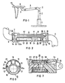
- a vertically extending support tube 2 is located on a base-like base part 1 fastened on the bottom attached, at the upper end of which an angle piece 3 is attached, to which one end of a parallelogram support arm 4 is articulated, at the other end of which a further angle piece 5 is articulated, to which a dental instrument table 6 is attached.
- the height of the instrument table 6 can be adjusted in a known area by means of the parallelogram support arm 4 in a known manner.
- another device e.g. B. an X-ray device or a lamp, be held. The latter are usually not held on a floor stand, but on a ceiling suspension.
- the parallelogram linkage is formed by a horizontally guided rod 11, which connects the two upper articulation axes 7, 8 of the four articulation axes 7 to 10 of the parallelogram, and a tubular link arm 12, which connects the lower articulation axes 9, 10 to one another.
- the link arm 12 consists of a tubular profile 13 shown in cross section in FIG. 3 with end faces 14 and 15 fastened to it on the end face and receiving the bearing bushes for the joint axes 9 and 10.
- the profile 13 forms a plurality of longitudinally extending, partially closed, partially open to the periphery guide channels 16 to 19.
- these are a central, centrally located guide channel 16 with a circular cross section, two guide channels 17 arranged symmetrically thereto and approximately triangular in cross section , a guide channel 18 located above the guide channel 16, open at the top and two guide channels 19 arranged thereon on both sides and also open to the periphery their edge 20a engages in a groove 21 provided in the profile 13, covered.
- the two outer guide channels 19 are used to guide various electrical and / or pneumatic and / or hydraulic supply lines leading from a junction box in the base part 1 to the consumers, in the present case to those on the instrument table 6 held handpieces.
- the cover cap 20 When the cover cap 20 is removed, the lines can be laid particularly easily within the support arm or replaced if necessary.
- the cover cap 20 forms a circular outer contour with the profile 13, the cover cap 20 covering approximately half the circumference of the profile.
- An extruded profile is advantageously used as the profile, the cover cap can expediently consist of plastic.
- a gas spring 22 is inserted into the peripherally closed guide channel 16 (FIG. 2).
- One end 22a is supported on a transverse pin 23 arranged in the end piece 14, and the free end of the piston rod 24 rests on one end face of a braking device 25, which will be explained in more detail later, the other end face of which forms an extension 26 on which, on the one hand, a guide roller 27 mounted and on the other hand, an articulated rod 28 connected to the articulated axis 8 are articulated.
- It is very easy to disassemble the gas spring for example to replace it with one with a stronger pressure force (for a higher weight load).
- the support arm 4 can be pivoted about the bearing axis 7. If you then remove the cross pin 23, the gas spring can be pulled out through the forwardly open end piece 14 (FIGS. 5/6).
- the joint axes between the parallelogram linkage arms and the two angle pieces 3 and 5 are covered by a bellows 29.
- the two end pieces 14, 15 contain, as shown in FIGS. 4 to 6 with reference to the end piece 14, plug pins 30 on both sides in cross section corresponding to the cross section of the guide channels 17; after insertion into the channels 17, they can be firmly connected to the tubular profile 13 in a suitable manner, advantageously by gluing.
- the structure of the braking device 25 is explained in more detail with reference to FIG. 7.
- the braking device 25 consists essentially of two screwed together plastic parts 33, 34 and a rubber-elastic brake element 35 which is inserted in an annular recess formed by a gradation in the diameter of the plastic parts 33, 34.
- the braking element 35 forms, together with an annular plastic part 36, a pressure chamber 37 which can be connected to a compressed air source via a conduit 38.
- the plastic part 33 has a notch 39 on the end face in which the end of the piston rod 24 can be supported.
- the braking device is used to support the arm with additional weight, eg. B. with temporarily placed on the instrument table 6 equipment, such as film viewer, tartar removal device, etc., in one to be able to lock the desired position.
- a valve for releasing compressed air from a compressed air source to the chamber 37 can expediently be provided in the vicinity of the instrument table 6.
- the non-pressurized jacket surface of the braking element 35 which is somewhat recessed relative to the lateral surfaces of the plastic parts 33, 34, lies against the walls of the tubular channel 16. In this position, the part 35 is blocked and no more desired displacement or adjustment of the support arm is possible.
- one or more friction elements can be provided instead of or in addition to the brake element 35, the friction force of which can be adjusted to a defined value, possibly variable.
- the setting can be done mechanically, pneumatically or hydraulically. Three variants are shown schematically in FIGS. 8 and 9.
- a braking device 40 similar to that shown in FIG. 7 is provided;
- several friction elements 41 arranged on the circumference are provided in this embodiment, the frictional force of which can be adjusted hydraulically with respect to the tube wall 16.
- an hydraulic actuating device, designated 42 is provided externally of the support arm, preferably in the vicinity of the instrument table 6, by means of which the frictional force of the brake elements 41 can be adjusted.
- the actuating device 42 consists of a cylinder 43 filled with a suitable liquid and a piston 45 which can be adjusted manually by means of the adjusting screw 44, and a line 47 leading into a chamber 46 of the braking device 40 corresponding to the chamber 37 in FIG. 7 Piston 45 the hydraulic fluid to be adjusted to the pressure required for adjusting the frictional force.
- the braking device 50 here consists of two half-shells 50a, 50b, of which the former consist of a friction lining, can be provided with a friction lining or can contain one or more friction elements.
- the half 50a provided with a friction lining 51 in the exemplary embodiment is actuated by means of actuators arranged in the other half shell 50b, e.g. B. in the form of a nut 54 guided in a threaded nut 54, with the interposition of several resilient elements, for. B. disc springs 53, pressed against the wall of the channel 16 in the assembled state.
- actuators arranged in the other half shell 50b, e.g. B. in the form of a nut 54 guided in a threaded nut 54, with the interposition of several resilient elements, for. B. disc springs 53, pressed against the wall of the channel 16 in the assembled state.
- Such a mechanical adjustment of the frictional force is appropriate if the weight load acting on the support arm is largely fixed, but an adjustment of the
- gas springs with integrated controllable valves can also be provided, which are triggered when the piston rod is actuated.
- a pneumatic control device in order to be able to control the trigger plunger of the gas spring for the release or blocking of the gas exchange within the chambers in the gas spring.
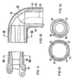
- Both elbows are constructed using the same components; they consist of a pipe bend 60 shown in longitudinal section in FIG. 10 and a joint head 61 attached to one end of the pipe bend, shown in section in FIG. 11.
- the pipe bend 60 in turn consists of a cast body 63 and two half-shells 64, 65 detachably held thereon on the dashed line 66 in a suitable manner, for. B. are connected by resilient locking elements.
- This structure has several advantages; by the fact that the outer, visible part of the arch is formed by the two plastic half-shells, the surface of the cast body itself need not be reworked. In particular, there is no need for relatively complex grinding, filling and painting work. Different color requests can be taken into account when creating the plastic half shells.
- the cast body 63 has the cross section shown in FIG. 12 at the end facing the support arm. From this it can be seen that the cast body has four evenly distributed circumferentially arranged, tapering to the arc grooves 67, which engage in the corresponding, longitudinal ribs 68 which the joint head 61 shown in longitudinal section in FIG. 11, which supports the unspecified bearing bushes Includes recording of the joint axes 8 and 10 ( Figure 2).
- the pipe bend 60 can now be placed on the joint head 61 either, as shown in FIG. 10, with the pipe end pointing downward or offset by 180 °, i. H. with the pipe end pointing upwards.
- these can, if desired, be suitably, e.g. B. permanently bonded together by gluing, pinning.
- the cast body 63 contains a recess 69 in the region of the arch, which is covered by the half-shell 64 in the attached state. After removing the half-shell 64, there is access from the outside to the inside of the arch, whereby z. B. within the support tube assembly 1 to 5 installed lines can be replaced very easily.
Landscapes
- Engineering & Computer Science (AREA)
- Health & Medical Sciences (AREA)
- Life Sciences & Earth Sciences (AREA)
- General Engineering & Computer Science (AREA)
- Animal Behavior & Ethology (AREA)
- Mechanical Engineering (AREA)
- Medical Informatics (AREA)
- Veterinary Medicine (AREA)
- Public Health (AREA)
- General Health & Medical Sciences (AREA)
- Surgery (AREA)
- High Energy & Nuclear Physics (AREA)
- Heart & Thoracic Surgery (AREA)
- Molecular Biology (AREA)
- Physics & Mathematics (AREA)
- Radiology & Medical Imaging (AREA)
- Pathology (AREA)
- Optics & Photonics (AREA)
- Nuclear Medicine, Radiotherapy & Molecular Imaging (AREA)
- Biomedical Technology (AREA)
- Biophysics (AREA)
- Manipulator (AREA)
- Dental Tools And Instruments Or Auxiliary Dental Instruments (AREA)
- Accommodation For Nursing Or Treatment Tables (AREA)
- Mutual Connection Of Rods And Tubes (AREA)
- Fittings On The Vehicle Exterior For Carrying Loads, And Devices For Holding Or Mounting Articles (AREA)
- Axle Suspensions And Sidecars For Cycles (AREA)
- Actuator (AREA)
- Vehicle Body Suspensions (AREA)
- Sampling And Sample Adjustment (AREA)
Claims (17)
Priority Applications (1)
| Application Number | Priority Date | Filing Date | Title |
|---|---|---|---|
| AT85115015T ATE40788T1 (de) | 1984-12-10 | 1985-11-27 | Parallelogrammtragarm mit kraefteausgleichsvorrichtung. |
Applications Claiming Priority (2)
| Application Number | Priority Date | Filing Date | Title |
|---|---|---|---|
| DE3445016 | 1984-12-10 | ||
| DE3445016 | 1984-12-10 |
Publications (2)
| Publication Number | Publication Date |
|---|---|
| EP0185229A1 EP0185229A1 (fr) | 1986-06-25 |
| EP0185229B1 true EP0185229B1 (fr) | 1989-02-15 |
Family
ID=6252386
Family Applications (1)
| Application Number | Title | Priority Date | Filing Date |
|---|---|---|---|
| EP85115015A Expired EP0185229B1 (fr) | 1984-12-10 | 1985-11-27 | Bras-support à parallélogramme avec équilibrage de forces |
Country Status (6)
| Country | Link |
|---|---|
| US (1) | US4657217A (fr) |
| EP (1) | EP0185229B1 (fr) |
| JP (1) | JPH0345723Y2 (fr) |
| AT (1) | ATE40788T1 (fr) |
| DE (1) | DE3568255D1 (fr) |
| YU (1) | YU188685A (fr) |
Families Citing this family (18)
| Publication number | Priority date | Publication date | Assignee | Title |
|---|---|---|---|---|
| US4714222A (en) * | 1984-12-10 | 1987-12-22 | Siemens Aktiengesellschaft | Bracket structure for dental purposes |
| US4783036A (en) * | 1987-04-16 | 1988-11-08 | Anthro Corporation | Adjustable support |
| US4836486A (en) * | 1987-04-16 | 1989-06-06 | Anthro Corporation | Adjustable support |
| DE3809266A1 (de) * | 1988-03-19 | 1988-09-22 | Mueholos Werk Alfred Mueller G | Schwenkarm fuer geraete, insbesondere medizinische |
| US5042763A (en) * | 1990-01-05 | 1991-08-27 | Wong William W M | Self-leveling portable camera support apparatus |
| DE19617937C1 (de) * | 1996-04-26 | 1997-09-25 | Ophthalmic Praxiseinrichtungen | Schwenkbare Trageinrichtung |
| NL1004116C2 (nl) * | 1996-09-26 | 1998-03-27 | Vogel S Holding Bv | Inrichtingen voor het ondersteunen van een elektrisch apparaat. |
| GB9904123D0 (en) * | 1999-02-23 | 1999-04-14 | Simons Janine | Arm support |
| FI111047B (fi) * | 1999-12-01 | 2003-05-30 | Instrumentarium Corp | Nivelvarsijärjestely erilaisten lääketieteellisten kuvauslaitteiden liittämiseksi nivelletysti tukirakenteisiin |
| US7124755B2 (en) * | 2001-12-21 | 2006-10-24 | Kimberly-Clark Worldwide, Inc. | Respiratory circuit support arm |
| US7014157B2 (en) * | 2002-10-31 | 2006-03-21 | Innovative Office Products, Inc. | Friction cylinder for a support device |
| US8794579B2 (en) * | 2005-06-03 | 2014-08-05 | Steelcase, Inc. | Support arm assembly |
| FI122296B (fi) * | 2006-11-21 | 2011-11-15 | Planmeca Oy | Hammashoitokoneen yhteydessä käytettävä kannatinelin |
| US8814224B2 (en) * | 2009-11-11 | 2014-08-26 | Hoffman Enclosures, Inc. | Enclosure suspension system with compression fitting |
| USD680223S1 (en) | 2011-10-19 | 2013-04-16 | Reliance Medical Products, Inc. | Examination chair |
| CN105003805B (zh) * | 2015-07-28 | 2017-03-22 | 迈柯唯医疗设备(苏州)有限公司 | 一种医用显示器支撑机构 |
| US20180080598A1 (en) * | 2016-09-20 | 2018-03-22 | Apple Inc. | Counterbalanced display stand |
| CN112856123B (zh) * | 2021-01-05 | 2022-12-30 | 厦门路桥景观艺术有限公司 | 一种景观园林施工放线辅助观瞄仪 |
Family Cites Families (10)
| Publication number | Priority date | Publication date | Assignee | Title |
|---|---|---|---|---|
| GB724471A (en) * | 1952-10-13 | 1955-02-23 | Ritter Co Inc | Counterbalancing mechanism |
| GB850239A (en) * | 1957-05-13 | 1960-10-05 | Ritter Co Inc | Counterbalancing mechanism |
| DE1294593B (de) * | 1964-09-07 | 1969-05-08 | Emda | Zahnaerztliches Geraet mit Instrumententisch |
| FR1455288A (fr) * | 1965-08-10 | 1966-04-01 | Emda | Tablette à instruments pour dentistes |
| DE1566209B2 (de) * | 1967-04-26 | 1978-09-28 | Emda Fabrik Elektro-Medizinischer Und Dentaler Apparate Georg Hartmann Gmbh & Co Kg, 6000 Frankfurt | Zahnarztliches Gerat |
| JPS5258284A (en) * | 1975-10-28 | 1977-05-13 | Jacobsen As J | Arm with balance spring |
| US4160536A (en) * | 1976-10-27 | 1979-07-10 | Jac. Jacobsen A/S | Counterbalanced arm |
| US4166602A (en) * | 1978-05-18 | 1979-09-04 | Pennwalt Corporation | Counterbalancing mechanism for X-ray tubeheads |
| US4397439A (en) * | 1981-02-13 | 1983-08-09 | Syntex (U.S.A.) Inc. | Brake assembly for dental tray support arm |
| DE3109721A1 (de) * | 1981-03-13 | 1982-09-23 | Kaltenbach & Voigt Gmbh & Co, 7950 Biberach | Zahnaerztlicher geraetestaender |
-
1985
- 1985-11-27 DE DE8585115015T patent/DE3568255D1/de not_active Expired
- 1985-11-27 EP EP85115015A patent/EP0185229B1/fr not_active Expired
- 1985-11-27 AT AT85115015T patent/ATE40788T1/de not_active IP Right Cessation
- 1985-12-03 JP JP1985187175U patent/JPH0345723Y2/ja not_active Expired
- 1985-12-04 YU YU01886/85A patent/YU188685A/xx unknown
- 1985-12-10 US US06/806,830 patent/US4657217A/en not_active Expired - Lifetime
Also Published As
| Publication number | Publication date |
|---|---|
| JPS61103109U (fr) | 1986-07-01 |
| US4657217A (en) | 1987-04-14 |
| JPH0345723Y2 (fr) | 1991-09-26 |
| YU188685A (en) | 1988-08-31 |
| EP0185229A1 (fr) | 1986-06-25 |
| ATE40788T1 (de) | 1989-03-15 |
| DE3568255D1 (en) | 1989-03-23 |
Similar Documents
| Publication | Publication Date | Title |
|---|---|---|
| EP0185229B1 (fr) | Bras-support à parallélogramme avec équilibrage de forces | |
| DE3429424C2 (fr) | ||
| DE3707046C2 (fr) | ||
| DE69326951T2 (de) | Künstliches gelenk mit einem hydraulischen dämpfenden zylinder | |
| DE69314188T2 (de) | Antriebselement zum transfer von vor- und rückwärtsrotations-bewegungen | |
| EP0097226A1 (fr) | Amortisseur hydraulique et articulation artificielle réalisée à l'aide d'un tel amortisseur | |
| CH670039A5 (fr) | ||
| DE4034188A1 (de) | Einstellbare teleskopvorrichtung | |
| EP1138449A1 (fr) | Dispositif pour équilibrer un robot grâce à un tuyau flexible gonflable | |
| DE3701172C2 (fr) | ||
| DE1912086C3 (de) | Gestängenachstelleinrichtung für das Bremsgestänge eines Eisenbahnwagens | |
| DE9014111U1 (de) | Stellelement, insbesondere für verstellbare Teile von Fahrzeugsitzen | |
| DE202011005203U1 (de) | Räumlich verstellbare Konsole | |
| DE1856267U (de) | Pneumatisch betaetigte greifzange. | |
| DE8436137U1 (de) | Parallelogrammtragarm mit Kräfteausgleichsvorrichtung | |
| DE3623143C2 (de) | Fluidbetätigter Zylinder | |
| DE3642956C2 (fr) | ||
| DE10104661B4 (de) | Aufhängevorrichtung für sich in vertikaler Richtung verschiebende Lasten, insbesondere Rohrleitungen und dergleichen | |
| DE2843727A1 (de) | Ausziehbare gewichtsausgleichseinrichtung fuer ein werkzeug, insbesondere montagewerkzeug | |
| DE19921553A1 (de) | Druckabschalteinrichtung für eine Hilfskraftlenkung in den Endstellungen des Lenkausschlages | |
| DE3834251A1 (de) | Instrumententragsaeule | |
| DE10296524T5 (de) | Abgasabscheider | |
| DE2659444B1 (de) | Tragarmkonstruktion mit Federgewichtsausgleich | |
| DE2654334A1 (de) | Tragarmkonstruktion mit federgewichtsausgleich | |
| DE4428990C2 (de) | Pneumatischer Stellantrieb |
Legal Events
| Date | Code | Title | Description |
|---|---|---|---|
| PUAI | Public reference made under article 153(3) epc to a published international application that has entered the european phase |
Free format text: ORIGINAL CODE: 0009012 |
|
| AK | Designated contracting states |
Kind code of ref document: A1 Designated state(s): AT DE FR GB IT SE |
|
| 17P | Request for examination filed |
Effective date: 19860728 |
|
| 17Q | First examination report despatched |
Effective date: 19871030 |
|
| GRAA | (expected) grant |
Free format text: ORIGINAL CODE: 0009210 |
|
| AK | Designated contracting states |
Kind code of ref document: B1 Designated state(s): AT DE FR GB IT SE |
|
| REF | Corresponds to: |
Ref document number: 40788 Country of ref document: AT Date of ref document: 19890315 Kind code of ref document: T |
|
| REF | Corresponds to: |
Ref document number: 3568255 Country of ref document: DE Date of ref document: 19890323 |
|
| ET | Fr: translation filed | ||
| ITF | It: translation for a ep patent filed | ||
| GBT | Gb: translation of ep patent filed (gb section 77(6)(a)/1977) | ||
| PLBI | Opposition filed |
Free format text: ORIGINAL CODE: 0009260 |
|
| 26 | Opposition filed |
Opponent name: RITTER GMBH DENTALEINRICHTUNGEN Effective date: 19891111 |
|
| PGFP | Annual fee paid to national office [announced via postgrant information from national office to epo] |
Ref country code: GB Payment date: 19911021 Year of fee payment: 7 |
|
| ITTA | It: last paid annual fee | ||
| PLBN | Opposition rejected |
Free format text: ORIGINAL CODE: 0009273 |
|
| STAA | Information on the status of an ep patent application or granted ep patent |
Free format text: STATUS: OPPOSITION REJECTED |
|
| 27O | Opposition rejected |
Effective date: 19911122 |
|
| PG25 | Lapsed in a contracting state [announced via postgrant information from national office to epo] |
Ref country code: GB Effective date: 19921127 |
|
| GBPC | Gb: european patent ceased through non-payment of renewal fee |
Effective date: 19921127 |
|
| EAL | Se: european patent in force in sweden |
Ref document number: 85115015.1 |
|
| REG | Reference to a national code |
Ref country code: FR Ref legal event code: TP |
|
| PGFP | Annual fee paid to national office [announced via postgrant information from national office to epo] |
Ref country code: FR Payment date: 20021119 Year of fee payment: 18 |
|
| PGFP | Annual fee paid to national office [announced via postgrant information from national office to epo] |
Ref country code: AT Payment date: 20021122 Year of fee payment: 18 |
|
| PGFP | Annual fee paid to national office [announced via postgrant information from national office to epo] |
Ref country code: SE Payment date: 20021125 Year of fee payment: 18 |
|
| PGFP | Annual fee paid to national office [announced via postgrant information from national office to epo] |
Ref country code: DE Payment date: 20021128 Year of fee payment: 18 |
|
| PG25 | Lapsed in a contracting state [announced via postgrant information from national office to epo] |
Ref country code: AT Free format text: LAPSE BECAUSE OF NON-PAYMENT OF DUE FEES Effective date: 20031127 |
|
| PG25 | Lapsed in a contracting state [announced via postgrant information from national office to epo] |
Ref country code: SE Free format text: LAPSE BECAUSE OF NON-PAYMENT OF DUE FEES Effective date: 20031128 |
|
| PG25 | Lapsed in a contracting state [announced via postgrant information from national office to epo] |
Ref country code: DE Free format text: LAPSE BECAUSE OF NON-PAYMENT OF DUE FEES Effective date: 20040602 |
|
| EUG | Se: european patent has lapsed | ||
| PG25 | Lapsed in a contracting state [announced via postgrant information from national office to epo] |
Ref country code: FR Free format text: LAPSE BECAUSE OF NON-PAYMENT OF DUE FEES Effective date: 20040730 |
|
| REG | Reference to a national code |
Ref country code: FR Ref legal event code: ST |