EP0097226A1 - Amortisseur hydraulique et articulation artificielle réalisée à l'aide d'un tel amortisseur - Google Patents
Amortisseur hydraulique et articulation artificielle réalisée à l'aide d'un tel amortisseur Download PDFInfo
- Publication number
- EP0097226A1 EP0097226A1 EP83103218A EP83103218A EP0097226A1 EP 0097226 A1 EP0097226 A1 EP 0097226A1 EP 83103218 A EP83103218 A EP 83103218A EP 83103218 A EP83103218 A EP 83103218A EP 0097226 A1 EP0097226 A1 EP 0097226A1
- Authority
- EP
- European Patent Office
- Prior art keywords
- piston
- cylinder
- joint part
- joint
- damping cylinder
- Prior art date
- Legal status (The legal status is an assumption and is not a legal conclusion. Google has not performed a legal analysis and makes no representation as to the accuracy of the status listed.)
- Granted
Links
- 239000006096 absorbing agent Substances 0.000 title 1
- 230000035939 shock Effects 0.000 title 1
- 238000013016 damping Methods 0.000 claims abstract description 71
- 239000012530 fluid Substances 0.000 claims abstract description 32
- 210000000629 knee joint Anatomy 0.000 claims abstract description 15
- 239000007788 liquid Substances 0.000 claims abstract description 7
- 238000007789 sealing Methods 0.000 claims description 13
- 244000309466 calf Species 0.000 description 4
- 238000005429 filling process Methods 0.000 description 4
- 238000005452 bending Methods 0.000 description 2
- 238000013022 venting Methods 0.000 description 2
- 230000004308 accommodation Effects 0.000 description 1
- 238000010276 construction Methods 0.000 description 1
- 238000001816 cooling Methods 0.000 description 1
- 230000000694 effects Effects 0.000 description 1
- 238000010438 heat treatment Methods 0.000 description 1
- 230000001771 impaired effect Effects 0.000 description 1
- 238000009434 installation Methods 0.000 description 1
- 238000013017 mechanical damping Methods 0.000 description 1
- 238000000034 method Methods 0.000 description 1
- 230000000149 penetrating effect Effects 0.000 description 1
- 238000003825 pressing Methods 0.000 description 1
- 230000001105 regulatory effect Effects 0.000 description 1
- 230000007704 transition Effects 0.000 description 1
- 210000000689 upper leg Anatomy 0.000 description 1
Images


Classifications
-
- F—MECHANICAL ENGINEERING; LIGHTING; HEATING; WEAPONS; BLASTING
- F16—ENGINEERING ELEMENTS AND UNITS; GENERAL MEASURES FOR PRODUCING AND MAINTAINING EFFECTIVE FUNCTIONING OF MACHINES OR INSTALLATIONS; THERMAL INSULATION IN GENERAL
- F16F—SPRINGS; SHOCK-ABSORBERS; MEANS FOR DAMPING VIBRATION
- F16F9/00—Springs, vibration-dampers, shock-absorbers, or similarly-constructed movement-dampers using a fluid or the equivalent as damping medium
- F16F9/32—Details
- F16F9/44—Means on or in the damper for manual or non-automatic adjustment; such means combined with temperature correction
-
- A—HUMAN NECESSITIES
- A61—MEDICAL OR VETERINARY SCIENCE; HYGIENE
- A61F—FILTERS IMPLANTABLE INTO BLOOD VESSELS; PROSTHESES; DEVICES PROVIDING PATENCY TO, OR PREVENTING COLLAPSING OF, TUBULAR STRUCTURES OF THE BODY, e.g. STENTS; ORTHOPAEDIC, NURSING OR CONTRACEPTIVE DEVICES; FOMENTATION; TREATMENT OR PROTECTION OF EYES OR EARS; BANDAGES, DRESSINGS OR ABSORBENT PADS; FIRST-AID KITS
- A61F2/00—Filters implantable into blood vessels; Prostheses, i.e. artificial substitutes or replacements for parts of the body; Appliances for connecting them with the body; Devices providing patency to, or preventing collapsing of, tubular structures of the body, e.g. stents
- A61F2/50—Prostheses not implantable in the body
- A61F2/60—Artificial legs or feet or parts thereof
- A61F2/64—Knee joints
-
- A—HUMAN NECESSITIES
- A61—MEDICAL OR VETERINARY SCIENCE; HYGIENE
- A61F—FILTERS IMPLANTABLE INTO BLOOD VESSELS; PROSTHESES; DEVICES PROVIDING PATENCY TO, OR PREVENTING COLLAPSING OF, TUBULAR STRUCTURES OF THE BODY, e.g. STENTS; ORTHOPAEDIC, NURSING OR CONTRACEPTIVE DEVICES; FOMENTATION; TREATMENT OR PROTECTION OF EYES OR EARS; BANDAGES, DRESSINGS OR ABSORBENT PADS; FIRST-AID KITS
- A61F2/00—Filters implantable into blood vessels; Prostheses, i.e. artificial substitutes or replacements for parts of the body; Appliances for connecting them with the body; Devices providing patency to, or preventing collapsing of, tubular structures of the body, e.g. stents
- A61F2/50—Prostheses not implantable in the body
- A61F2/68—Operating or control means
-
- F—MECHANICAL ENGINEERING; LIGHTING; HEATING; WEAPONS; BLASTING
- F16—ENGINEERING ELEMENTS AND UNITS; GENERAL MEASURES FOR PRODUCING AND MAINTAINING EFFECTIVE FUNCTIONING OF MACHINES OR INSTALLATIONS; THERMAL INSULATION IN GENERAL
- F16F—SPRINGS; SHOCK-ABSORBERS; MEANS FOR DAMPING VIBRATION
- F16F9/00—Springs, vibration-dampers, shock-absorbers, or similarly-constructed movement-dampers using a fluid or the equivalent as damping medium
- F16F9/10—Springs, vibration-dampers, shock-absorbers, or similarly-constructed movement-dampers using a fluid or the equivalent as damping medium using liquid only; using a fluid of which the nature is immaterial
- F16F9/14—Devices with one or more members, e.g. pistons, vanes, moving to and fro in chambers and using throttling effect
- F16F9/16—Devices with one or more members, e.g. pistons, vanes, moving to and fro in chambers and using throttling effect involving only straight-line movement of the effective parts
- F16F9/18—Devices with one or more members, e.g. pistons, vanes, moving to and fro in chambers and using throttling effect involving only straight-line movement of the effective parts with a closed cylinder and a piston separating two or more working spaces therein
- F16F9/20—Devices with one or more members, e.g. pistons, vanes, moving to and fro in chambers and using throttling effect involving only straight-line movement of the effective parts with a closed cylinder and a piston separating two or more working spaces therein with the piston-rod extending through both ends of the cylinder, e.g. constant-volume dampers
-
- A—HUMAN NECESSITIES
- A61—MEDICAL OR VETERINARY SCIENCE; HYGIENE
- A61F—FILTERS IMPLANTABLE INTO BLOOD VESSELS; PROSTHESES; DEVICES PROVIDING PATENCY TO, OR PREVENTING COLLAPSING OF, TUBULAR STRUCTURES OF THE BODY, e.g. STENTS; ORTHOPAEDIC, NURSING OR CONTRACEPTIVE DEVICES; FOMENTATION; TREATMENT OR PROTECTION OF EYES OR EARS; BANDAGES, DRESSINGS OR ABSORBENT PADS; FIRST-AID KITS
- A61F2/00—Filters implantable into blood vessels; Prostheses, i.e. artificial substitutes or replacements for parts of the body; Appliances for connecting them with the body; Devices providing patency to, or preventing collapsing of, tubular structures of the body, e.g. stents
- A61F2/50—Prostheses not implantable in the body
- A61F2/68—Operating or control means
- A61F2/74—Operating or control means fluid, i.e. hydraulic or pneumatic
-
- A—HUMAN NECESSITIES
- A61—MEDICAL OR VETERINARY SCIENCE; HYGIENE
- A61F—FILTERS IMPLANTABLE INTO BLOOD VESSELS; PROSTHESES; DEVICES PROVIDING PATENCY TO, OR PREVENTING COLLAPSING OF, TUBULAR STRUCTURES OF THE BODY, e.g. STENTS; ORTHOPAEDIC, NURSING OR CONTRACEPTIVE DEVICES; FOMENTATION; TREATMENT OR PROTECTION OF EYES OR EARS; BANDAGES, DRESSINGS OR ABSORBENT PADS; FIRST-AID KITS
- A61F2/00—Filters implantable into blood vessels; Prostheses, i.e. artificial substitutes or replacements for parts of the body; Appliances for connecting them with the body; Devices providing patency to, or preventing collapsing of, tubular structures of the body, e.g. stents
- A61F2/50—Prostheses not implantable in the body
- A61F2002/5003—Prostheses not implantable in the body having damping means, e.g. shock absorbers
- A61F2002/5006—Dampers, e.g. hydraulic damper
Definitions
- the invention relates to a hydraulic damping cylinder, in particular for damping the movement of artificial joints, with an annular chamber for the hydraulic fluid, which is divided into two partial chambers by an annular shoulder of a piston, with both sides of the shoulder determining the damping, with one inside of the piston arranged recess connected flow openings, the cross-section of the liquid passage formed by the flow openings and the recess being adjustable.
- the partial chambers are generally arranged axially one behind the other. It is also known to provide two cylinder chambers, the piston being able to reduce the volume of the first subchamber and pressing the hydraulic fluid into the second subchamber which can be enlarged in volume via a connecting line.
- the first sub-chamber is provided with a piston which can be displaced by the hydraulic fluid against the force of the restoring element.
- the invention is therefore based on the object of a hydraulic system.
- damping cylinders of the type mentioned which can be created in a small space and in particular can be accommodated in a space-saving manner in an artificial joint that a modular structure is possible.
- the recess is designed as an annular compensation chamber within the piston, that the inner wall of the compensation chamber, which is approximately inclined at the level of the flow openings, has an outer wall of a throttle piston, the relative axial position of which is adjustable relative to the piston, and that the throttle piston is hollow and comprises a restoring element.
- the first partial chamber is thus integrated into the piston.
- the ring-shaped design allows accommodation within the length of the piston.
- the shoulder provided with the flow opening allows an arrangement in which the hydraulic fluid has to flow in a very small way, so that the heating of the hydraulic fluid can be kept low.
- the two partial chambers are formed by the same chamber and are located on opposite sides of the shoulder of the piston.
- the shoulder thus moves back and forth in a camera, the reduction in size of the chamber on one side of the shoulder enlarging the chamber on the other side of the shoulder.
- the size of the flow opening can preferably be adjusted.
- This is preferably achieved in the piston according to the invention in that a throttle piston is mounted in the piston, the position of which can be adjusted relative to the piston and the wall of which changes the free width of the flow opening when its position relative to the piston is adjusted.
- an annular compensation chamber can be provided between the piston and the throttle piston, through which the hydraulic fluid flowing from the first sub-chamber flows into the second sub-chamber and vice versa.
- the hydraulic fluid thus passes from the first sub-chamber through a flow-through bore into the compensation chamber and from there through a further bore on the other side of the shoulder into the second sub-chamber.
- the boundary of the compensation chamber can preferably be formed with an inclined wall, which is displaceable between the two bores by changing the relative position of the throttle piston to the piston. This leaves the flow resistance is regulated by the connection between the first subchamber and the second subchamber.
- the piston and throttle piston are preferably hollow and comprise the cylindrical reset element, which is preferably formed by a helical spring. This allows a considerable reduction in the space required for the damping cylinder.
- the throttle piston can bear with an end face on an adjusting screw arranged in the piston.
- the screw that strikes the end face at an angle changes the relative position of the piston and throttle piston relative to one another due to their rotation.
- the housing of the cylinder has a rib-shaped outer surface in the region of the first partial chamber.
- the fins do the job of cooling fins by increasing the surface area of the cylinder through which heat can be given off to the environment.
- the sub-chamber located between the piston and the cylinder is closed off by a bottom screwable into the cylinder, which has a seal at its end facing the sub-chamber, which is intended for contact with the piston.
- the piston preferably has a length in the extended state with respect to the part of the cylinder which is provided with the internal thread for receiving the base, which length allows the base to be partially screwed on without the seal having sealing contact with the piston.
- the seal comes into sealing contact with the piston and maintains this during a further screwing-in movement of the piston.
- a seal can then preferably be provided in the outer wall of the base, which makes a sealing contact with the inner wall of the cylinder during the screwing-in movement, namely simultaneously with or after the sealing by the seal between the base and the piston.
- the filling process is extremely simple in the hydraulic damping cylinder according to the invention. When the bottom is unscrewed, the cylinder is fully extended and the flow opening fully opened.
- the hydraulic fluid is poured into the chamber between the piston and cylinder.
- the air in the compensation chamber prevents the hydraulic fluid from penetrating substantially into the compensation chamber.
- Sufficient hydraulic fluid is filled in that the liquid level is flush with the end of the piston.
- the bottom is screwed from above into the upward-facing end of the cylinder turned upside down in relation to its installation position.
- the annular wall closing the chamber comes into contact with the surface of the hydraulic fluid.
- the seal is not yet in sealing contact with the piston, so that the liquid continues is squeezed out at the top.
- the seal between the bottom and the piston receives the sealing contact and also the seal between the bottom and the cylinder.
- the sealing contact is maintained, as a result of which the hydraulic fluid is pressed through the flow opening into the compensation chamber.
- the air contained therein is compressed until the bottom is screwed in completely.
- the compressed air is compressed as an air cushion at the lower end of the compensation chamber in the individual position, so that when the bottom is screwed on, the hydraulic fluid is filled into the chamber between the piston and the cylinder, and the compensation chamber is also filled so that the hydraulic fluid filled part of the chamber is in contact with the partial chambers located between the cylinder and piston.
- Unscrewing the bottom therefore causes a metering of the hydraulic fluid, a complete venting of the working chambers and a partial venting of the compensation chamber and a filling of the compensation chamber, so that the hydraulic fluid contained therein can replace a possible loss of fluid in the working chambers.
- the invention further relates to an artificial joint, in particular a knee joint, with a joint axis, about which an upper joint part can be rotated relative to a lower joint part, and with a hydraulic damping cylinder attached to an intermediate joint upper part and lower joint part.
- an artificial joint in particular a knee joint
- a joint axis about which an upper joint part can be rotated relative to a lower joint part
- a hydraulic damping cylinder attached to an intermediate joint upper part and lower joint part.
- the artificial joint according to the invention is no larger than conventional artificial joints with mechanical damping. Therefore, the artificial joint according to the invention can easily be exchanged for a conventional joint, the skeletal! parts can remain completely unchanged. Since in the previously known artificial joints the hydraulic damping cylinder protruded into the calf part, an exchange with unchanged tubular skeleton parts was not possible. This exchange has now been made possible by the artificial joint according to the invention.
- the axis of the articulation of the damping cylinder on the upper joint part is below the joint axis when the joint is not flexed.
- an effective damping of the movement of the joint can be achieved in the area that must be effectively damped. If the joint is bent more strongly, the damping effect of the damping cylinder is eliminated, so that the knee joint can be flexed, for example, unhindered into the sitting position.
- a much stronger flexion can be achieved than with conventional joints, since the articulation has taken place above the joint axis, whereby the stronger flexion has been hindered.
- the damping cylinder one has upper approach that protrudes beyond the linkage and is attached with its end to the upper joint part.
- the articulation on the upper joint part is thus integrated into the arrangement of the damping cylinder. Only the extension projecting beyond the articulation is attached to the upper joint part. This can simplify assembly, since the entire damping arrangement can only be fastened with a few screws and can therefore be easily replaced if, for example, the damping cylinder has lost hydraulic fluid and no longer performs its damping function to the desired extent.
- the rotatable mounting of the damping cylinder with lateral bearing journals in the fork-shaped joint lower part also serves for better interchangeability.
- the bearing pins can preferably engage in bushings inserted from the outside into bores in the lower joint part. In this way, the damping cylinder can be replaced very easily since the bushings only have to be removed from the bores. This is particularly easy if the bushings are secured against falling out by springs. Then only the springs have to be loosened in order to be able to remove the bushings from the bores and to expose the damping cylinder. If the journals and bushes are conical, jamming of the damping cylinder is effectively prevented together with the sprung bearing. There is an axial self-adjustment by the conical bearing, so that a very safe function of the damping cylinder is guaranteed.
- stops are provided which limit the relative movement between the upper joint part and the lower joint part before the piston of the hydraulic cylinder hits the walls of the cylinder. It has been found that when the stops of the hydraulic cylinder are used to limit the movement of the artificial joint, the cylinder is subjected to considerable loads and is easily damaged, so that the function of the artificial joint is quickly impaired.
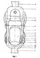
- FIGS. 1 to 3 show an artificial knee joint, which consists of an upper joint part 1 and a lower joint part 2, which are connected to one another by a joint axis 3.
- the upper joint part 1 has an adjustable connection 4 and the lower joint part 2 has an adjustable connection 5.
- a thigh can be connected to the upper joint part 1 and a calf part in the form of tubular skeleton parts to the lower joint part 2.
- the lower joint part 2 is fork-shaped and has two walls 6, 7 running parallel to one another, between which a hydraulic damping cylinder 8 is arranged.
- the hydraulic damping cylinder is fastened to the upper joint part 1 with an extension 9 through which a screw 10 is screwed into the upper joint part 1.
- the hydraulic damping cylinder 8 is connected to the attachment 9 via a swivel joint 11.
- the swivel joint 11 represents the articulation of the hydraulic damping cylinder on the upper joint part 1.
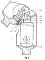
- the mounting of the hydraulic damper Cylinder 8 in the lower joint part 2 is made via bearing pins 12 pointing to the side walls 6, 7, which are surrounded by bushes 13, which in turn are inserted from the outside into bores 14 in the walls 6, 7.
- the outer walls of the journals 12 and the inner walls of the bushes 13 are conical, so that when the bushes 13 are fitted onto the journals 12, the hydraulic damping cylinder 8 is automatically centered in the lower joint part 2.
- the bushes 13 are each held by a resilient bracket 15, which rises above the bushes 13 on a recess 16 in the walls 6, 7 and rests resiliently against them.
- the part of the bracket 15 located there is
- Both the bottom 18 of the fork-shaped lower joint part 2 and the bottom 19 of the hydraulic damping cylinder 8 are curved, so that the hydraulic damping cylinder 8 can rotate about the bearing pin 12.
- stop strips 20 of the upper joint part 1 and lower joint part 2 lie one on top of the other and limit the uprighting movement of the artificial knee joint.
- FIG. 2 shows that in the upright state of the knee joint, the center point of the articulation 11 is a piece a lower than the center point of the joint axis 3.
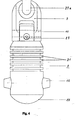
- FIG. 3 shows the knee joint from FIG. 2 in the bent state, ie in the sitting position.
- the flexion movement is in turn limited by the stop bar 20 of the lower joint part 2, with which an edge 21 on the back of the upper joint part 1 interacts.
- the inclination of the edge 21 is designed such that it lies flat on the stop bar 20 of the lower joint part 2. Due to the lower arrangement of the articulation 11 with respect to the articulation axis 3, a much stronger bending of the artificial joint can be realized than in the case of conventional artificial joints.
- the hydraulic damping cylinder is first compressed by the movement of the linkage 11 on a circular path up to a bending angle of approximately 90 °. Then the hydraulic damping cylinder 8 relaxes again somewhat, so that the restoring force of the hydraulic damping cylinder 8 holds the artificial joint in the end position shown in FIG. 3.
- the early ineffectiveness of the counterforce of the hydraulic damping cylinder 8 is a consequence of the low arrangement of the linkage 11 relative to the joint axis 3.
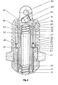
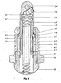
- FIG. 4 shows a view of a hydraulic cylinder 8 in the removed state.
- the two bearing journals 12 are molded onto the cylindrical base body.
- the base body is closed off by the convexly curved bottom 19.
- Above the bearing journal 12, the outer wall is provided with ribs 22, which enlarge the surface of the housing and serve to give off increased heat to the surroundings.
- FIG. 4 shows the swivel joint 11, below which there is an adjusting grub screw 23, the function of which is explained in more detail below. Beyond the swivel joint 11 is the approach 9, which has a recess 23 a for receiving the screw 10.
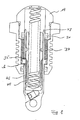
- Figures 5 and 6 illustrate the internal structure of the hydraulic damping cylinder 8, the 8-cylinder housing 24 consists of two parts that are screwed into each other.
- a piston 25 is guided in the cylindrical housing and is connected to an eyelet 26 for receiving an axis of rotation of the swivel joint 11.
- the piston 25 is hollow. It has an annular shoulder 26 which is displaceable in an annular chamber 28 formed between two webs 27 in the wall of the cylindrical housing 24.
- Figure 5 shows the piston in the inserted state
- Figure 6 shows the piston 25 in the extended state.
- the piston 25 is sealed off from the chamber 28 by means of two f0 rings 31, 32 inserted in annular grooves 29, 30.
- the outer surface of the shoulder 26 also has a groove 33, in which a further O-ring 34 is inserted.
- the piston 25 has two flow bores 35, 36 through which hydraulic fluid 37 in the chamber 28 can flow into the interior of the piston 25.
- a first partial chamber 38 is formed within the chamber 28 between the web 27 pointing towards the cylinder bottom 19 and the shoulder 26 (FIG. 6), while a second partial chamber 39 exists between the web 27 pointing towards the cylinder head and the shoulder 26.
- a throttle piston 40 In the hollow interior of the piston 25, another piston is guided as a throttle piston 40.
- the throttle piston is sealed with two O-rings 41 at its ends from the inside of the piston 25.
- the wall of the throttle piston runs over a slope 42 into an annular recess 43 which forms a compensation chamber.
- the setting of the relative position of the throttle piston 40 relative to the piston 25 is done with the help of the adjusting grub screw 23, which is inserted obliquely into the piston 25 and with a cylindrical inclined surface against the end wall 44 of the
- D rossel piston 40 presses.
- the counterforce to the adjusting force of the screw 23 is generated by a coil spring 45 which is mounted in the bottom 19 of the hydraulic damping cylinder 8 on the one hand and on the inside of the end wall 44 of the hollow throttle piston 40 on the other hand.
- the helical spring 45 presses the piston 25 together with the throttle piston 40 from the retracted position (FIG. 5) into the extended position (FIG. 6).
- first subchamber 38 and the second subchamber 39 in the same chamber 28 in the wall of the cylindrical housing 24 achieves a very space-saving arrangement.
- the pistons 25, 40 as hollow pistons, space can also be saved by accommodating the coil spring 45 as a restoring element.
- the setting of the damping force of the hydraulic damping cylinder 8 by means of the grub screw 23 and the throttle piston 40 is also done without additional space.
- FIGs 7 to 9 illustrate the filling process for the hydraulic fluid, which is extremely simple in the hydraulic damping cylinder according to the invention.
- the cylinder is in its upside-down position, that is, with its lower end up, filled with hydraulic fluid 37 by screwing on the bottom 19 and filling the hydraulic fluid 37 into the subchamber 39, the piston 25 being completely pulled out, so that the Shoulder 26 abuts the upper stop and the partial chamber 38 is initially practically compressed to zero.
- the flow opening 35 is open, practically no hydraulic fluid 37 flows into the compensation chamber 43, since the air therein cannot escape.
- the chamber 39 is open at the top because of the screwed-off base 19, the hydraulic fluid 37 can be filled in up to the end of the piston 25 pointing upwards.
- the bottom 19 is now screwed into the cylinder 8. In this case, presses its lower, the completion of the sub-chamber 39 image E nde annular surface 47 on the annular surface of the hydraulic fluid 37. Since the seal 31 in this position has and does not have any sealing contact with the piston 25 a between the floor 19 and cylinder 8 provided seal 46 of the bottom 19 also does not yet seal, part of the hydraulic fluid 37 escapes upwards out of the cylinder 8. When the bottom 19 is screwed in further, there is a sealing contact between the seal 31 and the piston 25. j To facilitate this process, the piston is on provided at its end with an inclined inward outer wall 48.
- this filling ensures that the hydraulic damping cylinder 8 functions properly the flow openings 35, 36 the hydraulic fluid can flow back and forth between the subchambers 38, 39.
- the compensation chamber 43 has an air-free filling toward the openings 35, 36 and is able to replace any liquid losses that may occur in the subchambers 38, 39.
- the compressed air cushion 49 does not prevent this, but rather relaxes slowly when liquid from the compensation chamber 43 reaches the subchambers 38, 39. The compressed air cushion 49 therefore exerts a certain elastic refill force.
Landscapes
- Health & Medical Sciences (AREA)
- Engineering & Computer Science (AREA)
- General Engineering & Computer Science (AREA)
- Transplantation (AREA)
- Life Sciences & Earth Sciences (AREA)
- Biomedical Technology (AREA)
- Heart & Thoracic Surgery (AREA)
- Vascular Medicine (AREA)
- Oral & Maxillofacial Surgery (AREA)
- Animal Behavior & Ethology (AREA)
- General Health & Medical Sciences (AREA)
- Public Health (AREA)
- Veterinary Medicine (AREA)
- Cardiology (AREA)
- Mechanical Engineering (AREA)
- Orthopedic Medicine & Surgery (AREA)
- Prostheses (AREA)
Priority Applications (4)
| Application Number | Priority Date | Filing Date | Title |
|---|---|---|---|
| AT83103218T ATE28724T1 (de) | 1982-06-18 | 1983-03-31 | Hydraulik-daempfzylinder und damit aufgebautes kuenstliches gelenk. |
| ES523234A ES8403584A1 (es) | 1982-06-18 | 1983-06-14 | "perfeccionamientos en los medios de amortiguacion de articulaciones artificiales" |
| JP10852383A JPS5957648A (ja) | 1982-06-18 | 1983-06-16 | 液圧緩衝シリンダおよびこれを用いて構成した人工関節 |
| BR8303245A BR8303245A (pt) | 1982-06-18 | 1983-06-17 | Cilindro hidraulico de amortecimento e articulacao artificial |
Applications Claiming Priority (2)
| Application Number | Priority Date | Filing Date | Title |
|---|---|---|---|
| DE3222885 | 1982-06-18 | ||
| DE3222885A DE3222885C2 (de) | 1982-06-18 | 1982-06-18 | Hydraulikdämpfer |
Publications (2)
| Publication Number | Publication Date |
|---|---|
| EP0097226A1 true EP0097226A1 (fr) | 1984-01-04 |
| EP0097226B1 EP0097226B1 (fr) | 1987-08-05 |
Family
ID=6166334
Family Applications (1)
| Application Number | Title | Priority Date | Filing Date |
|---|---|---|---|
| EP83103218A Expired EP0097226B1 (fr) | 1982-06-18 | 1983-03-31 | Amortisseur hydraulique et articulation artificielle réalisée à l'aide d'un tel amortisseur |
Country Status (4)
| Country | Link |
|---|---|
| US (1) | US4595179A (fr) |
| EP (1) | EP0097226B1 (fr) |
| CA (1) | CA1231204A (fr) |
| DE (2) | DE3222885C2 (fr) |
Cited By (5)
| Publication number | Priority date | Publication date | Assignee | Title |
|---|---|---|---|---|
| EP0309441A2 (fr) * | 1987-09-22 | 1989-03-29 | Otto Bock Orthopädische Industrie Besitz- und Verwaltungs-KG | Unité hydraulique avec cylindre et piston à double effet |
| FR2670118A1 (fr) * | 1990-11-19 | 1992-06-12 | Guillaud Jean Luo | Genoulliere a amortissement mecanique. |
| EP0560652A1 (fr) * | 1992-03-11 | 1993-09-15 | ETABLISSEMENTS PROTEOR Société anonyme dite: | Dispositif de régulation de la marche des amputés fémoraux |
| WO1994007442A1 (fr) * | 1992-10-02 | 1994-04-14 | Biedermann Motech Gmbh | Dispositif de commande de mouvements oscillants en phase |
| DE4338946C1 (de) * | 1993-11-15 | 1995-05-24 | Bock Orthopaed Ind | Prothesengelenk |
Families Citing this family (17)
| Publication number | Priority date | Publication date | Assignee | Title |
|---|---|---|---|---|
| US5092902A (en) * | 1990-08-16 | 1992-03-03 | Mauch Laboratories, Inc. | Hydraulic control unit for prosthetic leg |
| US5337737A (en) * | 1992-01-13 | 1994-08-16 | Albert Einstein College Of Medicine Of Yeshiva University | Dynamic orthosis with proportional resistance |
| US5405409A (en) * | 1992-12-21 | 1995-04-11 | Knoth; Donald E. | Hydraulic control unit for prosthetic leg |
| US5443521A (en) * | 1992-12-21 | 1995-08-22 | Mauch Laboratories, Inc. | Hydraulic control unit for prosthetic leg |
| US5542509A (en) * | 1994-03-11 | 1996-08-06 | Gabriel Ride Control Products, Inc. | Shock absorber having externally adjustable compression |
| EP0749539B1 (fr) * | 1994-03-11 | 2002-05-22 | Gabriel Ride Control Products, Inc. | Amortisseur a compression reglable de l'exterieur |
| US5862895A (en) * | 1994-03-17 | 1999-01-26 | Ricard; Andre | Adjustable variable oleopneumatic shock-absorbing device |
| US5899869A (en) * | 1997-12-22 | 1999-05-04 | Barrack, Jr.; Herb J. | Orthopedic appliance with weight activated brake and variable extension assist |
| US5961556A (en) * | 1996-12-31 | 1999-10-05 | Lord Corporation | Prosthetic suspension unit having elastomeric energy storage units |
| US5948021A (en) * | 1998-02-24 | 1999-09-07 | Hosmer-Dorrance Corporation | Hydraulic cylinders for limb gait control |
| DE202004008157U1 (de) * | 2004-05-19 | 2004-11-04 | medi Bayreuth Weihermüller & Voigtmann GmbH & Co. KG | Prothesengelenk |
| US7485152B2 (en) * | 2005-08-26 | 2009-02-03 | The Ohio Willow Wood Company | Prosthetic leg having electronically controlled prosthetic knee with regenerative braking feature |
| US20100148412A1 (en) * | 2008-12-12 | 2010-06-17 | Showa Corporation | Hydraulic shock absorber |
| US8928161B2 (en) | 2012-05-25 | 2015-01-06 | Kcf Technologies, Inc. | Apparatuses and methods for harvesting energy from prosthetic limbs |
| US9901466B2 (en) * | 2014-09-02 | 2018-02-27 | Ortotek Ortopedi Protez Ortez Rehabilitasyon Merkezi Ticaret Limited Sirketi | Threaded knee prosthesis joint |
| CN108799321A (zh) * | 2017-05-03 | 2018-11-13 | 天津张文发送商贸有限公司 | 可变阻尼关节之关节窝 |
| DE102019118422B3 (de) * | 2019-07-08 | 2021-01-07 | Otto Bock Healthcare Products Gmbh | Aktuator und Wärmespeicher für Aktuator |
Citations (5)
| Publication number | Priority date | Publication date | Assignee | Title |
|---|---|---|---|---|
| BE395063A (fr) * | ||||
| CH307417A (de) * | 1952-06-14 | 1955-05-31 | Fichtel & Sachs Ag | Stossdämpfer, insbesondere für Fahrzeuge. |
| DE1766909A1 (de) * | 1968-08-09 | 1971-09-16 | Blatchford & Sons Ltd | Kuenstliches Knie fuer Beinprothesen |
| US4212087A (en) * | 1978-11-16 | 1980-07-15 | Mortensen Lavaugh L | Prosthetic leg with a hydraulic control |
| DE3028608A1 (de) * | 1980-07-28 | 1982-02-11 | Bernd Ing. Krieg (grad.), 2000 Hamburg | Kunstbein mit hydraulischer pendel- und standphasensteuerung fuer oberschenkelamputationen sowie knie- und hueftgelenkexartikulationen |
Family Cites Families (14)
| Publication number | Priority date | Publication date | Assignee | Title |
|---|---|---|---|---|
| FR588584A (fr) * | 1924-11-07 | 1925-05-12 | Amortisseur de chocs à fluide pour suspension de voitures automobiles | |
| US1700044A (en) * | 1926-05-10 | 1929-01-22 | Hales Sidney Eales | Pneumatic and hydraulic apparatus |
| US1948185A (en) * | 1931-11-16 | 1934-02-20 | Joseph E Padgett | Shock absorber |
| US2213823A (en) * | 1939-08-07 | 1940-09-03 | Cleveland Pneumatic Tool Co | Shock absorbing strut |
| US2533008A (en) * | 1947-11-05 | 1950-12-05 | Gust Johnson | Artificial leg |
| DE821575C (de) * | 1950-03-14 | 1951-11-19 | Fichtel & Sachs Ag | Stossdaempfer |
| FR1154818A (fr) * | 1955-07-15 | 1958-04-17 | Armstrong Patents Company Ltd | Perfectionnements aux supports ou suspensions élastiques |
| DE1184223B (de) * | 1960-04-01 | 1964-12-23 | Fichtel & Sachs Ag | Hydropneumatische Abfederung mit Daempfung und Niveauregelung, insbesondere fuer Kraftfahrzeuge |
| US3240355A (en) * | 1963-10-21 | 1966-03-15 | Ellis Fluid Dynamics Corp | Hydraulic device |
| US3316558A (en) * | 1963-11-12 | 1967-05-02 | La Vaughn L Mortensen | Prosthetic leg with a hydraulic knee control |
| US3352386A (en) * | 1965-05-14 | 1967-11-14 | Houdaille Industries Inc | Piston-type hydraulic damper |
| DE1491236A1 (de) | 1965-09-28 | 1969-05-22 | Teufel Wilh Jul Fa | Kuenstliches Kniegelenk fuer Beinprothesen |
| US3837292A (en) * | 1969-08-22 | 1974-09-24 | D Wiebe | Hydraulic truck snubber |
| JPS5557537U (fr) * | 1978-10-14 | 1980-04-18 |
-
1982
- 1982-06-18 DE DE3222885A patent/DE3222885C2/de not_active Expired
-
1983
- 1983-03-31 DE DE8383103218T patent/DE3372841D1/de not_active Expired
- 1983-03-31 EP EP83103218A patent/EP0097226B1/fr not_active Expired
- 1983-06-17 US US06/504,847 patent/US4595179A/en not_active Expired - Fee Related
- 1983-06-20 CA CA000430787A patent/CA1231204A/fr not_active Expired
Patent Citations (5)
| Publication number | Priority date | Publication date | Assignee | Title |
|---|---|---|---|---|
| BE395063A (fr) * | ||||
| CH307417A (de) * | 1952-06-14 | 1955-05-31 | Fichtel & Sachs Ag | Stossdämpfer, insbesondere für Fahrzeuge. |
| DE1766909A1 (de) * | 1968-08-09 | 1971-09-16 | Blatchford & Sons Ltd | Kuenstliches Knie fuer Beinprothesen |
| US4212087A (en) * | 1978-11-16 | 1980-07-15 | Mortensen Lavaugh L | Prosthetic leg with a hydraulic control |
| DE3028608A1 (de) * | 1980-07-28 | 1982-02-11 | Bernd Ing. Krieg (grad.), 2000 Hamburg | Kunstbein mit hydraulischer pendel- und standphasensteuerung fuer oberschenkelamputationen sowie knie- und hueftgelenkexartikulationen |
Cited By (8)
| Publication number | Priority date | Publication date | Assignee | Title |
|---|---|---|---|---|
| EP0309441A2 (fr) * | 1987-09-22 | 1989-03-29 | Otto Bock Orthopädische Industrie Besitz- und Verwaltungs-KG | Unité hydraulique avec cylindre et piston à double effet |
| EP0309441A3 (en) * | 1987-09-22 | 1989-10-18 | Otto Bock Orthopadische Industrie Kg | Double acting hydraulic piston cylinder unit |
| FR2670118A1 (fr) * | 1990-11-19 | 1992-06-12 | Guillaud Jean Luo | Genoulliere a amortissement mecanique. |
| EP0560652A1 (fr) * | 1992-03-11 | 1993-09-15 | ETABLISSEMENTS PROTEOR Société anonyme dite: | Dispositif de régulation de la marche des amputés fémoraux |
| FR2688404A1 (fr) * | 1992-03-11 | 1993-09-17 | Proteor Sa | Dispositif de regulation hydraulique de la marche des amputes femoraux. |
| US5376138A (en) * | 1992-03-11 | 1994-12-27 | Etablissements Proteor Sa | Hydraulic device for correcting the gait of a femoral amputee |
| WO1994007442A1 (fr) * | 1992-10-02 | 1994-04-14 | Biedermann Motech Gmbh | Dispositif de commande de mouvements oscillants en phase |
| DE4338946C1 (de) * | 1993-11-15 | 1995-05-24 | Bock Orthopaed Ind | Prothesengelenk |
Also Published As
| Publication number | Publication date |
|---|---|
| EP0097226B1 (fr) | 1987-08-05 |
| US4595179A (en) | 1986-06-17 |
| CA1231204A (fr) | 1988-01-12 |
| DE3372841D1 (en) | 1987-09-10 |
| DE3222885C2 (de) | 1986-04-30 |
| DE3222885A1 (de) | 1983-12-29 |
Similar Documents
| Publication | Publication Date | Title |
|---|---|---|
| EP0097226B1 (fr) | Amortisseur hydraulique et articulation artificielle réalisée à l'aide d'un tel amortisseur | |
| DE69326951T2 (de) | Künstliches gelenk mit einem hydraulischen dämpfenden zylinder | |
| DE69929148T2 (de) | Rotationsdämpfer | |
| DE69524250T2 (de) | Rotationsdämpfer in einer kniegelenkprothese | |
| DE2649520C2 (fr) | ||
| DE60114584T2 (de) | Schwingungsdämpfungssystem mit einem hydraulischen dämpfer, welcher über eine feldempfindliche flüssigkeit gesteuert wird | |
| DE69317737T2 (de) | Vorrichtung für Stossdämpfer | |
| DE19800373A1 (de) | Dämpfer | |
| DE4219141A1 (de) | Hydraulischer daempfer | |
| DE2819918A1 (de) | Anbauvorrichtung mit einer kupplungsstange fuer ein an die hebevorrichtung eines schleppers anzuschliessendes arbeitsgeraet | |
| DE2320913A1 (de) | Hydraulischer stossdaempfer | |
| EP0654254A1 (fr) | Prothèse d'articulation | |
| EP0185229B1 (fr) | Bras-support à parallélogramme avec équilibrage de forces | |
| DE1976494U (de) | Tuerschliesser mit teleskop-gasfeder. | |
| DE3521862C2 (fr) | ||
| DE102017106568B4 (de) | Verbrennungsmotor mit variabler verdichtung | |
| DE102018120002B3 (de) | Verriegelungsmechanismus für längenveränderbare Pleuelstangen | |
| DE1075277B (de) | Beinprothese fur Oberschenkelamputierte | |
| EP0525507A2 (fr) | Dispositif de réglage d'un actionneur pour régler la cylindrée d'un machine hydrostatique | |
| DE69925439T2 (de) | Verriegelbarer Hebelmechanismus | |
| DE3534387A1 (de) | Vorgesteuertes 3/2-wegesitzventil | |
| DE2721121A1 (de) | Gabelbein fuer motorraeder | |
| DE2806929C2 (de) | Fluidbetätigter Servomotor mit Nachlaufsteuerung | |
| EP0074496B1 (fr) | Dispositif de vanne, en particulier pour machine à moulage sous pression | |
| DE10012066B4 (de) | Mehrwegeventil (Pilotventilbehälter) |
Legal Events
| Date | Code | Title | Description |
|---|---|---|---|
| PUAI | Public reference made under article 153(3) epc to a published international application that has entered the european phase |
Free format text: ORIGINAL CODE: 0009012 |
|
| AK | Designated contracting states |
Designated state(s): AT DE FR GB IT NL SE |
|
| ITCL | It: translation for ep claims filed |
Representative=s name: MODIANO & ASSOCIATI S.R.L. |
|
| EL | Fr: translation of claims filed | ||
| TCNL | Nl: translation of patent claims filed | ||
| 17P | Request for examination filed |
Effective date: 19840615 |
|
| RAP1 | Party data changed (applicant data changed or rights of an application transferred) |
Owner name: OTTO BOCK ORTHOPAEDISCHE INDUSTRIE BESITZ- UND VER |
|
| GRAA | (expected) grant |
Free format text: ORIGINAL CODE: 0009210 |
|
| AK | Designated contracting states |
Kind code of ref document: B1 Designated state(s): AT DE FR GB IT NL SE |
|
| REF | Corresponds to: |
Ref document number: 28724 Country of ref document: AT Date of ref document: 19870815 Kind code of ref document: T |
|
| REF | Corresponds to: |
Ref document number: 3372841 Country of ref document: DE Date of ref document: 19870910 |
|
| ITF | It: translation for a ep patent filed | ||
| ET | Fr: translation filed | ||
| PLBE | No opposition filed within time limit |
Free format text: ORIGINAL CODE: 0009261 |
|
| STAA | Information on the status of an ep patent application or granted ep patent |
Free format text: STATUS: NO OPPOSITION FILED WITHIN TIME LIMIT |
|
| 26N | No opposition filed | ||
| PGFP | Annual fee paid to national office [announced via postgrant information from national office to epo] |
Ref country code: DE Payment date: 19910305 Year of fee payment: 9 |
|
| PGFP | Annual fee paid to national office [announced via postgrant information from national office to epo] |
Ref country code: SE Payment date: 19910306 Year of fee payment: 9 |
|
| PGFP | Annual fee paid to national office [announced via postgrant information from national office to epo] |
Ref country code: FR Payment date: 19910315 Year of fee payment: 9 |
|
| PGFP | Annual fee paid to national office [announced via postgrant information from national office to epo] |
Ref country code: GB Payment date: 19910318 Year of fee payment: 9 |
|
| PGFP | Annual fee paid to national office [announced via postgrant information from national office to epo] |
Ref country code: AT Payment date: 19910328 Year of fee payment: 9 |
|
| ITTA | It: last paid annual fee | ||
| PGFP | Annual fee paid to national office [announced via postgrant information from national office to epo] |
Ref country code: NL Payment date: 19910331 Year of fee payment: 9 |
|
| PG25 | Lapsed in a contracting state [announced via postgrant information from national office to epo] |
Ref country code: GB Effective date: 19920331 Ref country code: AT Effective date: 19920331 |
|
| PG25 | Lapsed in a contracting state [announced via postgrant information from national office to epo] |
Ref country code: SE Effective date: 19920401 |
|
| PG25 | Lapsed in a contracting state [announced via postgrant information from national office to epo] |
Ref country code: NL Effective date: 19921001 |
|
| NLV4 | Nl: lapsed or anulled due to non-payment of the annual fee | ||
| GBPC | Gb: european patent ceased through non-payment of renewal fee | ||
| PG25 | Lapsed in a contracting state [announced via postgrant information from national office to epo] |
Ref country code: FR Effective date: 19921130 |
|
| PG25 | Lapsed in a contracting state [announced via postgrant information from national office to epo] |
Ref country code: DE Effective date: 19921201 |
|
| REG | Reference to a national code |
Ref country code: FR Ref legal event code: ST |
|
| EUG | Se: european patent has lapsed |
Ref document number: 83103218.0 Effective date: 19921108 |