EP0183000A2 - Fixation pour ski - Google Patents
Fixation pour ski Download PDFInfo
- Publication number
- EP0183000A2 EP0183000A2 EP85112147A EP85112147A EP0183000A2 EP 0183000 A2 EP0183000 A2 EP 0183000A2 EP 85112147 A EP85112147 A EP 85112147A EP 85112147 A EP85112147 A EP 85112147A EP 0183000 A2 EP0183000 A2 EP 0183000A2
- Authority
- EP
- European Patent Office
- Prior art keywords
- ski binding
- binding according
- section
- spring
- ski
- Prior art date
- Legal status (The legal status is an assumption and is not a legal conclusion. Google has not performed a legal analysis and makes no representation as to the accuracy of the status listed.)
- Granted
Links
Images


Classifications
-
- A—HUMAN NECESSITIES
- A63—SPORTS; GAMES; AMUSEMENTS
- A63C—SKATES; SKIS; ROLLER SKATES; DESIGN OR LAYOUT OF COURTS, RINKS OR THE LIKE
- A63C9/00—Ski bindings
- A63C9/20—Non-self-releasing bindings with special sole edge holders instead of toe-straps
Definitions
- the invention relates to a ski binding according to the preamble of claim 1.
- Such a ski binding has become known from AT-PS 351 983, in which the shoe to be fastened has a relatively extended sole extension, which is provided with a flexible zone lying directly in front of the shoe, which allows the heel to be raised.
- the attachment point of the sole extension lies in front of this flexible zone and is therefore relatively far from the shoe.
- the end area of the sole extension is connected as firmly as possible to the ski by the sole extension in a ski-proof tip pocket is inserted and held in place, for example by screwing.
- the invention is based on the consideration that the length of the sole extension, which is required in the known device, makes walking without skis uncomfortable and also because of the large distance between the shoe and the point where the shoe attaches to the binding is, the binding aligns the shoe only imperfectly in the longitudinal direction of the ski.
- the object of the invention is to eliminate these disadvantages and to create a ski binding in which the connection point between binding and boot is closer to the boot than the horizontal axis of rotation of the binding. This allows the use of a simple lock to hold the shoe in the binding and frees the bracket from the function of continuously aligning the shoe in the longitudinal direction of the ski.
- the retaining bracket only has the function of preventing the shoe from moving up or down, whereas the locking pins prevent displacement in the longitudinal direction of the ski and rotation about a vertical axis. Any side walls of the bracket provided only have the task of guiding the shoe when getting into the binding (cf. AT-PS 142 943).
- the measure of claim 2 will possible to close the binding simply by pivoting the shoe inserted into the bracket together with the latter, whereupon the releasable lock engages between the bracket and the pivoting part and fixes the closed position.
- the object of claim 3 also aims in this direction.
- the features of claim 4 again have the advantage that the lock designed as a spring-loaded pawl can be released with the ski pole, so that, with such a construction, it is not necessary to bend down to get in or out is.
- ski binding The structure of the ski binding is simplified by the subjects of claims 5 and 6. In claim 7, a particularly easy-to-produce variant of the first embodiment is protected.
- the two functions are divided into two springs. It has proven to be advantageous if different materials are used for both springs.
- the pawl-side spring section is designed as a hollow body.
- the approach of the pivot part in grooves can be inserted into a recess provided in the base plate-side section of the spring element.
- the pawl-side section of the spring element is made of the material of the full body and is of stepped construction. In all embodiments, this ensures that the pawl-side section of the spring element is supported on the attachment of the pivoting part - while maintaining a resilient support.
- the measure of claim 16 has the advantage that it pulls the sole extension into the ski binding, thereby improving the hold of the ski boot in the ski binding.
- the object of claim 17 ensures that the bracket of the springs or springs during the boarding process at an angle to Base plate is held, which makes safe boarding possible.
- the thickness of the approach of the pivot member is independent of the spring element, and it can be made thicker or thinner without having to change the dimensions of the spring element.
- the subject matter of claim 19 enables a central attack of the swivel part on the spring element without the thickness of the extension of the swivel part being influenced.
- claim 21 facilitates free deformation of the detent spring.
- the measure of claim 24 changes the ratio of the spring force of the detent spring to that of the main spring in the first phase of the compression.
- the direction of evasion of the detent spring is precisely determined during compression.
- the detent spring is simultaneously used as a cover, which prevents snow and dirt from penetrating into the interior of the ski binding prevented.
- the measure of claim 28 favors both the boarding process and the disembarking process.
- the measure of claim 29 has the effect that the distance of the front of the locking pins along which the sole extension is retracted is additionally lengthened.
- the shoe is secured against relative movement relative to the retaining bracket on its underside and by the features of claim 32 on its top.
- the subject of claim 33 has the advantage that by arranging two nu ten, on the one hand, the safety of the sole extension of the shoe against twisting relative to the holding bracket is increased, but on the other hand, no unreasonable material weaknesses occur either in the holding bracket or in the sole extension.
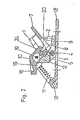
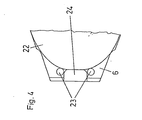
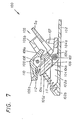
- the binding according to the invention makes it possible to fasten a shoe 22 which is only provided with a relatively short sole extension 6, in which through openings 23 are provided for receiving locking pins 2 of the binding (FIGS. 1 and 4).
- the binding for fastening such a shoe has a holding bracket 1 which overlaps the edge of the sole extension 6 of the shoe 22 and thus fixes it in the vertical direction.
- a locking pin 2-carrying pivot part 3 cooperates with the retaining bracket 1, in particular in FIGS. 2 and 3. Both the retaining bracket 1 and the pivoting part 3 are mounted on a transverse axis 4, a spring 5 designed as a leg spring pivoting the retaining bracket 1 into the position shown in FIG. 2, provided that the pawl 10 still to be discussed does not prevent this.
- the pivot part 3 is under the action of a weak spring 11, which is supported via an iider bearing 15 at the same time on a vertical extension 12 of the pivot part 3 and on the pawl 10, on the ski-fixed base body 18, which carries the transverse axis 4.
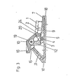
- the shoe 22 When entering the open binding shown in FIG. 2, the shoe 22 is inserted obliquely into the holding bracket 1, the pawl 10 projecting into the holding bracket being released by a corresponding recess 24 in the sole extension 6. The shoe is then pivoted downward together with the holding bracket 1 into the position shown in FIG. 3 and held by the locking pins which penetrate the through openings 23 of the sole extension 6.
- the binding is closed and the retaining bracket 1 and swivel part 3, which together hold the sole extension 6, can be pivoted upwards about the transverse axis 4 against the action of the spring 11.
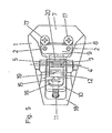
- the swivel part 3 is made of elastic material and is provided with a bending edge 14 which allows it to be swiveled up relative to its front edge fastened to the ski with screws 21.
- the construction according to FIG. 6 is simpler compared to that according to FIGS. 1 to 5 in that the pivoting part 3 also takes over the function of the base body 18, on the other hand a bending edge is one for permanent stresses less suitable axis of rotation than the transverse axis 4 according to FIGS. 1 to 5.
- the embodiment according to FIG. 6 will therefore mainly be chosen when value is placed on a particularly simple construction.
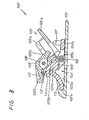
- 100 denotes the ski binding in its entirety. It has a base plate 102, which has raised edges 102a in the region of its two long sides. A transverse axis 103 is supported in these edges 102a, on which both a swivel part 104 and a holding bracket 105 are mounted.
- the holding bracket 105 has a plate 105a and two lateral guides 105b for an extension of the sole of the ski boot.
- the bracket 105 is provided with a web 105c, which has a locking groove 105d.
- there is a leg spring 106 on the transverse axis 103 which strives to pivot the retaining bracket 105 counterclockwise upwards.
- the swiveling part 104 is designed approximately as a bell crank. On its lever arm 104a, which is directed towards the end of the ski, it carries two locking pins 107, which are directed upwards and are intended for engagement in corresponding holes in the sole extension of the ski boot. In the other lever arm 104b, an axle 108 is fastened, on which a pawl 109 is pivotally mounted.
- the pawl 109 is also designed as a two-armed lever, one lever arm 109a carrying a latching nose, whereas the other lever arm 109b has a bulge 110 for engaging the tip of a ski pole.
- a helical compression spring 111 is supported on an abutment 102b of the base plate 102 the upper end abuts an extension 104c of the swivel part 104. With this approach 104c the lower end of a second compression spring 112 is also in contact, which serves to press the pawl 109 into its locked position.
- the dimensions of the web 105c of the holding bracket 105 and the lever arm 109a of the pawl 109 are selected such that the other lever arm 109b is pressed against the shoulder 104c of the pivoting part 104 during a pivoting movement and the spring 112 is fully compressed in the process. This leads to an increase in the force required for boarding, and it is achieved that, when boarding the binding, the swivel part 104 is not pressed down before the shoe does not come off the neck taps 107 is detected. The ski boot is thus fixed in the ski binding 100.
- the swivel part 104 which is now firmly connected to the holding bracket 105 via the pawl 109, is swiveled counterclockwise against the force of the compression spring 111.
- the compression spring 111 is compressed somewhat. Under the influence of the compression spring 111, the unit of the swivel part 104 and the holding bracket 105 is swiveled back clockwise again at the end of a cross-country skiing step.
- the tip of a ski pole is inserted into the bulge 110 and the pawl 109 is pivoted counterclockwise.
- the locking lug on the lever arm 109a of the pawl 109 leaves the locking groove 105d in the holding bracket 105, as a result of which the connection between the pivoting part 104 and the holding bracket is released.
- the retaining bracket 105 can therefore move under the influence of the leg spring 106 into the position shown in FIG. 7, in which the locking pins 107 have already left the holes in the sole extension of the ski boot. The ski boot can now be pulled out of the ski binding 100.
- the embodiment 100 'according to FIG. 8 is very similar to the embodiment described first. It differs from it only in that, instead of the helical compression spring 111, an elastic block 113 made of plastic or rubber is provided between an abutment 102'b of the base plate 102 'and an extension 104' c of a swivel part 104 '.
- the remaining elements correspond to those of the first Execution, the respective reference numbers being provided with a dash to distinguish them.
- the function of this ski binding 100 ' is also analogous to that of the first embodiment.
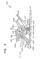
- the embodiment 100 "according to FIG. 9 differs from the two previous ones primarily in that instead of two springs an integrally formed spring element 113 'made of plastic or rubber is provided which is divided into two sections by a shoulder 104" c of the swivel part , of which one section 113 'a lies between the abutment 102 "b of the base plate 102" and the shoulder 104 "c of the swivel part and the other section 113' b lies between the shoulder 104" c of the swivel part and the pawl 109 " Section 113 'b has a smaller cross section than the other section 113' a, furthermore the spring element 113 'has an extension 113' g which engages over the shoulder 104 "c of the swivel part 104".
- pins 107 “have a rectangular cross-section, their front including an acute angle ⁇ with the lever arm 104" a of the pivoting part 104 "of the ski binding.
- the section 113 "a designed as a solid body has a rectangular recess 113" c, into which the attachment of the swivel part can be inserted.
- the section 113 "b of the spring element running between the attachment of the swivel part and the pawl is designed as a hollow body.
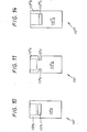
- Fig. 11 shows a similar embodiment of a spring element 113 "', which differs from the embodiment according to Fig. 10 only in that it has two grooves 113"', in which the fork-shaped extension of the pivot member can engage.
- the spring element 113 IV according to FIGS. 12a, b, c is characterized in that the section between the attachment of the swivel part and the pawl is designed as an upwardly projecting central rib 113 IV e. Otherwise, this spring element 113 IV also has a rectangular recess 113 IV c, into which the attachment of the swivel part can be inserted.
- the variant of a spring element 113 V according to FIGS. 13a, b, c differs from the previous one in that instead of a single rib there are two lateral ribs 113 V f. Otherwise, this spring element 113 V is also provided with grooves 113 V d, which are intended for a fork-shaped extension of the pivoting member.
- a spring element 113 VI is shown, in which the section 113 VI b between the attachment of the pivot part and the pawl has the shape of a rectangular frame in plan view. Furthermore, the spring element 113 VI has a rectangular recess 113 VI c, in which the approach of Swivel part can be inserted.
- the ski binding is designated in its entirety by 200. It has a base plate 202 which has raised edges 202a in the region of its two long sides. A transverse axis 203 is supported in these edges 202a, on which both a pivoting part 204 and a holding bracket 205 are mounted.
- the holding bracket 205 has a plate 205a and two lateral guides 205b for an extension of the sole of the ski boot. On its upper side, the two lateral guides 205b carry a transverse wall which has a slot 205f running in the longitudinal direction of the ski. This slot 205f serves to ensure reliable clamping of the ski boot even when the holes in the sole extension are already worn out.
- the bracket 205 is provided with a web 205c, which has a locking groove 205d.
- there is a leg spring 206 on the transverse axis 203 which strives to pivot the bracket 205 counterclockwise upwards.
- the swivel part 204 is designed approximately as an angle lever. It carries on its lever arm 204a directed towards the end of the ski two upward locking pins 207 which are intended to engage in corresponding holes in the sole extension of the ski boot. An axis 208 is fastened in the other lever arm 204b, on which a pawl 209 is pivotably mounted.
- the pawl 209 is also designed as a two-armed lever, the one lever arm 209b having a bulge 210 for engaging the tip of a ski pole.
- a spring element 213 made of plastic or rubber.
- This spring element 213 has at least one shoulder 213c, on which a shoulder 204c of the swivel part 204 is supported. That section of the spring element 213, which forms the main spring 213a and is located between the abutment 202b of the base plate 202 and the extension 204c of the swivel part 204, has a substantially larger cross section than the other section, which serves as a detent spring 213b and between the extension 204c and the pawl 209 is.
- the headband 205 includes the base plate 202 at an angle between 30 and 45 o, which facilitate entry and the risk of these, sliding of the To prevent skis when entering.
- the ski shoe is therefore displaced along the plate 205a against the web 205c until the holes of the sole extension of the ski shoe come to rest over the locking pin 207.
- the ski boot is then pressed down.
- the holding bracket 205 is pivoted about the transverse axis 203 against the force of the leg spring 206, with the locking pins 207 pulling the shoe into the holding bracket 205.
- the lever arm 209a of the pawl 209 slides over the web 205c of the holding bracket 205 until the nose of the lever arm 209a comes to rest in the latching groove 205d.
- the swivel part 204 which is now connected via the pawl 209 with the Retaining bracket 205 is firmly connected, pivoted counterclockwise against the force of the main spring 213a of the spring element 213.
- the main spring 213a is compressed.
- the unit of swivel part 204 and holding bracket 205 is swiveled back clockwise at the end of a cross-country skiing step.
- the tip of a ski pole is inserted into the bulge 210 and the pawl 209 is pivoted counterclockwise.
- the locking lug on the lever arm 209a of the pawl 209 leaves the locking groove 205d in the mounting bracket 205, as a result of which the connection between the pivoting part 204 and mounting bracket 205 is released.
- the retaining bracket 205 can therefore move under the influence of the leg spring 206 into the position shown in FIG. 15, in which the locking pins 207 have already left the holes in the sole extension of the ski boot. The ski boot can now be pulled out of the ski binding 200.
- the spring element 213 'shown in FIGS. 16a and 16b differs from the spring element 213 in that paragraphs 213'c are arranged on both sides of its longitudinal central plane, on which the fork-shaped extension of the pivoting part is supported at its end. This makes it possible to exert a symmetrical load on the spring element 213 '.
- the spring element 213 "according to FIG. 17 is characterized in that the detent spring 213" b has a constant cross-section over its entire length and protrude upwards in the form of a main spring 213 "a the rib is formed.
- the detent spring 213 "'b is approximately C-shaped in plan view. As a result, the spring element 213"' is secured against slipping off the attachment of the pivoting part, not shown in FIG. 18, to the front and to the sides.
- the embodiment of a spring element 213 IV according to FIG. 19 differs from that according to FIG. 18 in that the detent spring 213 IV b is provided in the region of the transition from the leg of the C to the transverse web with slots 213 IV d which pass through the respective edges .
- the spring element 213 V according to FIG. 20 is characterized in that the detent spring 213 V b consists of a central part with parallel walls, to which projections 213 e directed towards one side are attached, which have a triangular cross section.
- the ski binding in its entirety is designated by 300. It has a base plate 302, which is in the region of its two long sides. has raised edges 302a. A transverse axis 303 is supported in these edges 302a, on which both a swivel part 304 and a holding bracket 305 are mounted.
- the holding bracket 305 has a plate 305a and two lateral guides 305b for an extension of the sole of the ski boot.
- the holding bracket 305 is provided with a web 305c, which has a locking groove 305d.
- a leg spring 306 which strives to pivot the bracket 305 counterclockwise upwards.
- the swivel part 304 is designed approximately as an angle lever. On its lever arm 304a, which is directed towards the end of the ski, it carries two locking pins 307 which are directed upwards and are intended for engagement in corresponding holes in the sole extension of the ski boot. Each locking pin 307 has a base 307a, which protrudes normally upward from the lever arm 304a of the pivoting part, and a sloping upper section 307b, which is attached to the upper end of the base and is inclined towards the base of the ski and with the arm 304a of the pivot member 304 at an angle ß 50-80 0 includes.
- This height of the base 307a to the length of the upper section 307b is in a ratio of 1: 3 to 1: 6, in the present exemplary embodiment 1: 4.
- the end face of the upper section 307b runs at least approximately parallel to the lever arm 304a of the swivel part 304.
- an axis 308 is fastened, on which a pawl 309 is pivotally mounted.
- the pawl 309 is also designed as a two-armed lever, one lever arm 309a carrying a latching nose, whereas the other lever arm 309b has a bulge 310 for engaging the tip of a ski pole.
- a helical compression spring 311 is supported on an abutment 302b of the base plate 302, the upper end of which rests on a shoulder 304c of the swivel part 304.
- 304c further stands the lower end of a second compression spring 312 in contact, which serves to press the pawl 309 into its locked position.
- the swivel part 304 which is now firmly connected to the retaining bracket 305 via the pawl 309, is swiveled counterclockwise against the force of the compression spring 311.
- the compression spring 311 is compressed somewhat.
- the unit of swivel part 304 and holding bracket 305 is swiveled back clockwise at the end of a cross-country skiing step.
- the tip of a ski pole is inserted into the bulge 310 and the pawl 309 is countered pivoted counterclockwise.
- the locking lug on the lever arm 309a of the pawl 309 leaves the locking groove 305d in the holding bracket 305, as a result of which the connection between the pivoting part 304 and the holding bracket is released.
- the retaining bracket 305 can therefore move under the influence of the leg spring 306 into the position shown in FIG. 22, in which the locking pins 307 have already left the holes in the sole extension of the ski boot. The ski boot can now be pulled out of the ski binding 300.
- the front of the base 307'a opposite the lever arm of the pivoting part 304'a is shown in FIG. 23, 304 'at an angle ⁇ of 80 0 inclined. This angle can be 80-90 °.
- the transition of the front surface from the base 307'a to the front surface of the upper section 307'b is rounded. This particularly makes it easier to get out of the binding with the shoe.
- the locking pin 307 "shown in FIG. 24 is similar to the last described. It also has a base 307" a and an upper section 307 "b attached to its upper end.
- the upper section 307" b is on its front side in the area of its End convexly curved. This makes it easier to get started with the ski boot.
- the holding bracket 405 shown in FIG. 25 has a base plate 405a and two lateral guides 405b arranged thereon, which enclose an acute angle with one another and for receiving a sole extension of a not shown Ski boots are intended, the side walls of which are at the same angle to one another.
- the two lateral guides 405b carry a wall 405e parallel to the base plate 405a, which is provided with guide surfaces 405f for the ski boot that run in the longitudinal direction of the ski.
- the guide surfaces 405f can run parallel to one another, as shown in FIG. 27; however, they can also converge at an angle between 60 ° and 89 0 59 '59 ".
- the holding bracket 405 is provided with a web 405c which has a latching groove 405d.
- two grooves 405i are formed which are symmetrical with respect to the vertical longitudinal center plane of the ski binding and which are laterally delimited by guide surfaces 405g and 405h. These guide surfaces 405g and 405h are either normal to the base plate 405a or they enclose an acute angle with this.
Landscapes
- Footwear And Its Accessory, Manufacturing Method And Apparatuses (AREA)
Applications Claiming Priority (10)
| Application Number | Priority Date | Filing Date | Title |
|---|---|---|---|
| AT3049/84 | 1984-09-26 | ||
| AT304984A AT387912B (de) | 1984-09-26 | 1984-09-26 | Skibindung |
| AT0094985A AT390008B (de) | 1984-09-26 | 1985-03-29 | Skibindung fuer einen langlauf- oder tourenski |
| AT949/85 | 1985-03-29 | ||
| AT0131985A AT394812B (de) | 1985-03-29 | 1985-05-03 | Skibindung fuer einen langlauf- oder tourenski |
| AT1319/85 | 1985-05-03 | ||
| AT0135585A AT390009B (de) | 1984-09-26 | 1985-05-07 | Skibindung fuer einen langlauf- oder tourenski |
| AT1355/85 | 1985-05-07 | ||
| AT0135685A AT390383B (de) | 1984-09-26 | 1985-05-07 | Skibindung fuer einen langlauf- oder tourenski |
| AT1356/85 | 1985-05-07 |
Publications (3)
| Publication Number | Publication Date |
|---|---|
| EP0183000A2 true EP0183000A2 (fr) | 1986-06-04 |
| EP0183000A3 EP0183000A3 (en) | 1987-04-01 |
| EP0183000B1 EP0183000B1 (fr) | 1990-04-25 |
Family
ID=27506224
Family Applications (1)
| Application Number | Title | Priority Date | Filing Date |
|---|---|---|---|
| EP19850112147 Expired - Lifetime EP0183000B1 (fr) | 1984-09-26 | 1985-09-25 | Fixation pour ski |
Country Status (2)
| Country | Link |
|---|---|
| EP (1) | EP0183000B1 (fr) |
| DE (1) | DE3577278D1 (fr) |
Cited By (13)
| Publication number | Priority date | Publication date | Assignee | Title |
|---|---|---|---|---|
| DE3612658A1 (de) * | 1985-05-10 | 1986-11-13 | TMC Corp., Baar, Zug | Skibindung fuer den langlauf |
| WO1987007845A1 (fr) * | 1986-06-23 | 1987-12-30 | Tmc Corporation | Fixation pour ski de fond |
| EP0257282A3 (en) * | 1986-08-25 | 1988-07-20 | Tmc Corporation | Ski binding for cross-country or touring skis |
| EP0254094A3 (en) * | 1986-07-14 | 1988-07-27 | Tmc Corporation | Skibinding |
| FR2610836A1 (fr) * | 1987-02-13 | 1988-08-19 | Salomon Sa | Fixation pour ski de fond |
| FR2616079A2 (fr) * | 1987-06-05 | 1988-12-09 | Salomon Sa | Fixation pour ski de fond |
| FR2622462A1 (fr) * | 1987-10-29 | 1989-05-05 | Rossignol Sa | Dispositif destine a la fixation d'une chaussure sur un ski de fond |
| US4909532A (en) * | 1987-02-13 | 1990-03-20 | Salomon S.A. | Cross-country ski binding |
| AT390384B (de) * | 1984-09-26 | 1990-04-25 | Amf Sport Freizeitgeraete | Skibindung fuer einen langlauf- oder tourenski |
| US4925206A (en) * | 1987-08-26 | 1990-05-15 | Salomon S.A. | Cross-country ski binding |
| WO1991015275A1 (fr) * | 1990-03-30 | 1991-10-17 | Tmc Corporation | Fixation pour ski de fond ou de randonnee |
| US5193840A (en) * | 1990-03-30 | 1993-03-16 | Htm Sport- Und Freizeitgeraete Gesellschaft M.B.H. | Ski binding for a cross country ski or touring ski |
| US6402184B1 (en) * | 1998-03-06 | 2002-06-11 | Rottefella As | Binding for cross-country or trail skis |
Family Cites Families (3)
| Publication number | Priority date | Publication date | Assignee | Title |
|---|---|---|---|---|
| CH518107A (de) * | 1970-06-08 | 1972-01-31 | Glutz Blotzheim Nachfolger Ag | Skibindung für Langlauf- und Tourenzwecke |
| DE3045701C2 (de) * | 1980-12-04 | 1983-09-01 | Geze Gmbh, 7250 Leonberg | Langlaufbindung |
| FR2527081A1 (fr) * | 1982-05-21 | 1983-11-25 | Look Sa | Fixation pour ski de fond |
-
1985
- 1985-09-25 DE DE8585112147T patent/DE3577278D1/de not_active Expired - Lifetime
- 1985-09-25 EP EP19850112147 patent/EP0183000B1/fr not_active Expired - Lifetime
Cited By (14)
| Publication number | Priority date | Publication date | Assignee | Title |
|---|---|---|---|---|
| AT390384B (de) * | 1984-09-26 | 1990-04-25 | Amf Sport Freizeitgeraete | Skibindung fuer einen langlauf- oder tourenski |
| DE3612658A1 (de) * | 1985-05-10 | 1986-11-13 | TMC Corp., Baar, Zug | Skibindung fuer den langlauf |
| WO1987007845A1 (fr) * | 1986-06-23 | 1987-12-30 | Tmc Corporation | Fixation pour ski de fond |
| EP0254094A3 (en) * | 1986-07-14 | 1988-07-27 | Tmc Corporation | Skibinding |
| EP0257282A3 (en) * | 1986-08-25 | 1988-07-20 | Tmc Corporation | Ski binding for cross-country or touring skis |
| FR2610836A1 (fr) * | 1987-02-13 | 1988-08-19 | Salomon Sa | Fixation pour ski de fond |
| US4909532A (en) * | 1987-02-13 | 1990-03-20 | Salomon S.A. | Cross-country ski binding |
| FR2616079A2 (fr) * | 1987-06-05 | 1988-12-09 | Salomon Sa | Fixation pour ski de fond |
| US4925206A (en) * | 1987-08-26 | 1990-05-15 | Salomon S.A. | Cross-country ski binding |
| FR2622462A1 (fr) * | 1987-10-29 | 1989-05-05 | Rossignol Sa | Dispositif destine a la fixation d'une chaussure sur un ski de fond |
| WO1991015275A1 (fr) * | 1990-03-30 | 1991-10-17 | Tmc Corporation | Fixation pour ski de fond ou de randonnee |
| US5193840A (en) * | 1990-03-30 | 1993-03-16 | Htm Sport- Und Freizeitgeraete Gesellschaft M.B.H. | Ski binding for a cross country ski or touring ski |
| AT398279B (de) * | 1990-03-30 | 1994-11-25 | Tyrolia Freizeitgeraete | Skibindung für einen langlauf- oder tourenski |
| US6402184B1 (en) * | 1998-03-06 | 2002-06-11 | Rottefella As | Binding for cross-country or trail skis |
Also Published As
| Publication number | Publication date |
|---|---|
| DE3577278D1 (de) | 1990-05-31 |
| EP0183000A3 (en) | 1987-04-01 |
| EP0183000B1 (fr) | 1990-04-25 |
Similar Documents
| Publication | Publication Date | Title |
|---|---|---|
| CH624304A5 (fr) | ||
| DE2815167A1 (de) | Langlaufschibindung und dazugehoeriger langlaufschischuh | |
| DE3151584A1 (de) | Bindungsgesamtheit eines schuhs mit einem ski, insbesondere einem langlaufski | |
| EP0183000A2 (fr) | Fixation pour ski | |
| DE8432700U1 (de) | Skistiefel | |
| DE69504518T2 (de) | Bindung für einen schuh auf einem snowboard | |
| DE3708838A1 (de) | Anordnung zum festhalten eines ski-schuhs auf einem langlauf- oder touren-ski | |
| EP0167765B1 (fr) | Chaussure de ski | |
| DE2927059A1 (de) | Skischuh mit integrierter skibindung | |
| DE3707116C2 (de) | Skibindung für einen Langlauf- oder Touren-Ski | |
| EP0151975B1 (fr) | Cross-country ski | |
| DE3151585C2 (fr) | ||
| DE3405861A1 (de) | Langlauf- bzw. wanderbindung | |
| DE69604350T2 (de) | Gleitbrett mit Plattform zur Aufnahme und Erhöhung der Skibindung | |
| EP0434663A2 (fr) | Elément amortisseur pour chaussures de ski | |
| DE2657257A1 (de) | Skibindung, insbesondere fuer langlauf | |
| CH653265A5 (de) | Verstelleinrichtung fuer backen. | |
| EP0272317B1 (fr) | Fixation de securite pour ski | |
| AT398279B (de) | Skibindung für einen langlauf- oder tourenski | |
| DE60117339T2 (de) | Sportschuh mit in Querrichtung verstellbarer Spannvorrichtung | |
| DE2906484A1 (de) | Langlauf-skischuh | |
| AT395947B (de) | Skibindung | |
| DE4416531C2 (de) | Snowboardbindung | |
| AT240227B (de) | Skibindung | |
| EP0129535A1 (fr) | Ensemble de fixation pour ski de fond avec la chaussure |
Legal Events
| Date | Code | Title | Description |
|---|---|---|---|
| PUAI | Public reference made under article 153(3) epc to a published international application that has entered the european phase |
Free format text: ORIGINAL CODE: 0009012 |
|
| AK | Designated contracting states |
Kind code of ref document: A2 Designated state(s): CH DE FR LI |
|
| PUAL | Search report despatched |
Free format text: ORIGINAL CODE: 0009013 |
|
| AK | Designated contracting states |
Kind code of ref document: A3 Designated state(s): CH DE FR LI |
|
| 17P | Request for examination filed |
Effective date: 19870527 |
|
| 17Q | First examination report despatched |
Effective date: 19880824 |
|
| GRAA | (expected) grant |
Free format text: ORIGINAL CODE: 0009210 |
|
| AK | Designated contracting states |
Kind code of ref document: B1 Designated state(s): CH DE FR LI |
|
| REF | Corresponds to: |
Ref document number: 3577278 Country of ref document: DE Date of ref document: 19900531 |
|
| ET | Fr: translation filed | ||
| PLBE | No opposition filed within time limit |
Free format text: ORIGINAL CODE: 0009261 |
|
| STAA | Information on the status of an ep patent application or granted ep patent |
Free format text: STATUS: NO OPPOSITION FILED WITHIN TIME LIMIT |
|
| 26N | No opposition filed | ||
| REG | Reference to a national code |
Ref country code: CH Ref legal event code: PUE Owner name: AMF CORPORATION TRANSFER- HTM SPORTS CORP. Ref country code: CH Ref legal event code: PFA Free format text: TMC CORPORATION |
|
| REG | Reference to a national code |
Ref country code: FR Ref legal event code: TP Ref country code: FR Ref legal event code: CD |
|
| REG | Reference to a national code |
Ref country code: CH Ref legal event code: PFA Free format text: HTM SPORT- UND FREIZEITGERAETE AKTIENGESELLSCHAFT |
|
| REG | Reference to a national code |
Ref country code: FR Ref legal event code: TP |
|
| PGFP | Annual fee paid to national office [announced via postgrant information from national office to epo] |
Ref country code: FR Payment date: 19950720 Year of fee payment: 11 |
|
| PGFP | Annual fee paid to national office [announced via postgrant information from national office to epo] |
Ref country code: DE Payment date: 19950721 Year of fee payment: 11 |
|
| PGFP | Annual fee paid to national office [announced via postgrant information from national office to epo] |
Ref country code: CH Payment date: 19951002 Year of fee payment: 11 |
|
| PG25 | Lapsed in a contracting state [announced via postgrant information from national office to epo] |
Ref country code: LI Effective date: 19960930 Ref country code: FR Effective date: 19960930 Ref country code: CH Effective date: 19960930 |
|
| REG | Reference to a national code |
Ref country code: CH Ref legal event code: PL |
|
| PG25 | Lapsed in a contracting state [announced via postgrant information from national office to epo] |
Ref country code: DE Effective date: 19970603 |
|
| REG | Reference to a national code |
Ref country code: FR Ref legal event code: ST |
|
| REG | Reference to a national code |
Ref country code: FR Ref legal event code: ST |