EP0182001A2 - Procédé et appareil pour la fabrication d'un tube ondulé flexible ainsi que tube ondulé flexible obtenu par ce procédé - Google Patents
Procédé et appareil pour la fabrication d'un tube ondulé flexible ainsi que tube ondulé flexible obtenu par ce procédé Download PDFInfo
- Publication number
- EP0182001A2 EP0182001A2 EP85107929A EP85107929A EP0182001A2 EP 0182001 A2 EP0182001 A2 EP 0182001A2 EP 85107929 A EP85107929 A EP 85107929A EP 85107929 A EP85107929 A EP 85107929A EP 0182001 A2 EP0182001 A2 EP 0182001A2
- Authority
- EP
- European Patent Office
- Prior art keywords
- shaft
- rotation
- wave
- mold
- tube
- Prior art date
- Legal status (The legal status is an assumption and is not a legal conclusion. Google has not performed a legal analysis and makes no representation as to the accuracy of the status listed.)
- Granted
Links
Images


Classifications
-
- F—MECHANICAL ENGINEERING; LIGHTING; HEATING; WEAPONS; BLASTING
- F16—ENGINEERING ELEMENTS AND UNITS; GENERAL MEASURES FOR PRODUCING AND MAINTAINING EFFECTIVE FUNCTIONING OF MACHINES OR INSTALLATIONS; THERMAL INSULATION IN GENERAL
- F16L—PIPES; JOINTS OR FITTINGS FOR PIPES; SUPPORTS FOR PIPES, CABLES OR PROTECTIVE TUBING; MEANS FOR THERMAL INSULATION IN GENERAL
- F16L11/00—Hoses, i.e. flexible pipes
- F16L11/14—Hoses, i.e. flexible pipes made of rigid material, e.g. metal or hard plastics
- F16L11/16—Hoses, i.e. flexible pipes made of rigid material, e.g. metal or hard plastics wound from profiled strips or bands
-
- B—PERFORMING OPERATIONS; TRANSPORTING
- B21—MECHANICAL METAL-WORKING WITHOUT ESSENTIALLY REMOVING MATERIAL; PUNCHING METAL
- B21C—MANUFACTURE OF METAL SHEETS, WIRE, RODS, TUBES, PROFILES OR LIKE SEMI-MANUFACTURED PRODUCTS OTHERWISE THAN BY ROLLING; AUXILIARY OPERATIONS USED IN CONNECTION WITH METAL-WORKING WITHOUT ESSENTIALLY REMOVING MATERIAL
- B21C37/00—Manufacture of metal sheets, rods, wire, tubes, profiles or like semi-manufactured products, not otherwise provided for; Manufacture of tubes of special shape
- B21C37/06—Manufacture of metal sheets, rods, wire, tubes, profiles or like semi-manufactured products, not otherwise provided for; Manufacture of tubes of special shape of tubes or metal hoses; Combined procedures for making tubes, e.g. for making multi-wall tubes
- B21C37/12—Making tubes or metal hoses with helically arranged seams
- B21C37/121—Making tubes or metal hoses with helically arranged seams with seams being neither welded nor soldered
-
- B—PERFORMING OPERATIONS; TRANSPORTING
- B21—MECHANICAL METAL-WORKING WITHOUT ESSENTIALLY REMOVING MATERIAL; PUNCHING METAL
- B21C—MANUFACTURE OF METAL SHEETS, WIRE, RODS, TUBES, PROFILES OR LIKE SEMI-MANUFACTURED PRODUCTS OTHERWISE THAN BY ROLLING; AUXILIARY OPERATIONS USED IN CONNECTION WITH METAL-WORKING WITHOUT ESSENTIALLY REMOVING MATERIAL
- B21C37/00—Manufacture of metal sheets, rods, wire, tubes, profiles or like semi-manufactured products, not otherwise provided for; Manufacture of tubes of special shape
- B21C37/06—Manufacture of metal sheets, rods, wire, tubes, profiles or like semi-manufactured products, not otherwise provided for; Manufacture of tubes of special shape of tubes or metal hoses; Combined procedures for making tubes, e.g. for making multi-wall tubes
- B21C37/12—Making tubes or metal hoses with helically arranged seams
- B21C37/124—Making tubes or metal hoses with helically arranged seams the tubes having a special shape, e.g. with corrugated wall, flexible tubes
Definitions
- the invention relates to a method and a device for producing a flexible corrugated tube by helically winding a thin metal strip with shafts running parallel to its longitudinal direction, at least one shaft of two successive turns being nested and connected to one another.
- Such flexible corrugated pipes are used in the heating, air conditioning and ventilation areas.
- a very thin, narrow, flat metal strip is first pre-corrugated in a profiling system with the aid of several shaping rollers in such a way that the corrugation valleys and wave crests run parallel to the longitudinal direction of the strip.
- This pre-corrugated tape is wound up and can then be processed into a tube on a tube winding machine.
- the tube is produced in the tube winding machine by helically winding the pre-corrugated strip, the edges of adjacent turns being connected to one another will.
- the most varied types of connection are known, for example gluing, welding, folding, depressing a shaft crest in places or the like. More.
- the object of the invention is therefore to propose a method of the type mentioned at the outset, with which a water-tight and gas-tight flexible corrugated pipe, for example also on a construction site, can be produced in a simple and material-saving manner, which has great flexibility.
- interlocking shaft is initially circumferentially compressed in such a way that the shaft flanks of the shaft lie flat on top of one another, that the pressed shaft is rolled up from the apex of the shaft to the shaft base and that the rolled-up shaft is then pressed into the shaft base .
- a device for performing the method with a Winding device for guiding the finished tube and with a pair of infeed rollers arranged at the entry point of the strip into the winding device and acting on the two broad sides of the strip, which mutually connect the adjacent turns in the tube one infeed roller about an axis of rotation inside and the other infeed roller is arranged rotatably about an axis of rotation outside of the winding device, according to the invention a shaping tool which compresses and rolls together the interlocking shaft of the incoming strip is arranged on the axis of rotation of the upper feed roller.
- the molding tool is advantageously designed as a continuous tool with a molding gap for the shaft.
- the mold gap of the molding tool is preferably curved in the shape of an arc, the center or centers of curvature being located above the lower feed roller.
- the radius of curvature advantageously corresponds to the curvature of the mold gap approximately the radius of the pipe to be manufactured.
- the mold is initially conical to a narrow gap from its inlet to its outlet and then narrowing like a screw to an approximately round opening.
- the molding tool is preferably arranged on the axis of rotation of the upper feed roller in such a way that it is a round opening trained outlet lies approximately on the connecting line of the axes of rotation of the two inlet rollers and that the inlet of the molding tool is in front of this connecting line, as seen in the direction of entry of the belt.
- Press rings for pressing the deformed shaft into the shaft base are preferably arranged on the axes of rotation of the inlet rollers.
- the pressing rings are advantageously arranged on the outlet side of the winding device at a distance from the molding tool, which is equal to the distance between the deformed shafts of the tube.
- the method according to the invention first compresses the circumferentially in the axial direction and then from the crest of the shaft Rolled nested wave into the bottom of the shaft pressed into the bottom of the shaft.
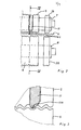
- a device for producing a flexible corrugated tube by helically winding a metal strip 4 has a winding device 1 for guiding the finished tube 2.
- the winding device 1 has guide rollers 3 arranged on a circle for guiding the tube, which are rotatable about axes, not shown.
- a pair of entry rollers 5 and 6 is arranged, the upper entry roller 5 being rotatable about an axis of rotation 7 which is located within the winding device 1, and the bottom entry roller 6 being arranged to be rotatable about an axis of rotation 8 , which is arranged outside the winding device 1.
- the inlet rollers 5 and 6 can be driven by a drive, not shown.
- the inlet rollers act on the two broad sides of the supplied tape 4 and bring about the mutual connection of the turns adjacent in the tube 2.
- the tape 4 is fed to the pair of feed rollers 5 and 6 via an adjustable pressure roller 9 arranged in front of the winding device. Further pairs of feed rollers 10 are arranged in front of the pressure roller 9.
- connection of the individual winding layers of the tube to one another takes place in that first of all one shaft two at a time other turns are placed one inside the other, the nested shaft is compressed all around in the axial direction of the tube in such a way that the wave flanks of the shaft lie flat on top of one another, so that the flattened wave is rolled up from the apex of the shaft to the bottom of the shaft and that the rolled-up shaft is then pressed into the bottom of the shaft.
- the infeed rollers 5 and 6 have a profile corresponding to the band 4 fed.
- Fig o 2 and 3 is on the top axis of rotation 7 of the upper input roller 5, a compressing and rolling said nested waves of the incoming strip 4 effecting mold 11 having a mold gap 11a (FIG. 4).
- the molding gap 11a of the molding tool is curved in an arc shape, the center of curvature being above the lower feed roller 6 and above the upper axis 7.
- the molding tool 11 has a clamping device 12, so that the molding tool is displaceably and rotatably arranged on the axis of rotation 7 and can be fixed on the axis of rotation 7 with the aid of the clamping device 12.
- the molding tool 11 is designed as a continuous tool for the shaft to be deformed which is to be deformed.
- the mold 11 is from its inlet 13 to its outlet 14 (Fig. 5) initially conical to a narrow gap and then narrowing like a screw to an approximately round opening.
- the molding tool is arranged on the axis of rotation 7 of the upper infeed roller 5 such that its outlet 14, which is designed as a round opening, lies approximately on the connecting line 15 of the axes of rotation 7 and 8 of the two infeed rollers 5 and 6 and that the inlet 13 of the molding tool in the infeed direction of the belt 4, indicated by the arrow 16, lies before this connecting line.
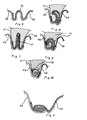
- FIG. 6 shows in the cutting direction 16 of the strip in different sections the deformation of the interlocking shafts of the strip and the shape of the molding tool.
- a shaft of the incoming strip 4b is inserted into a shaft of the already wound strip 4a immediately before the inlet 13 of the molding tool 11.
- the shaft 4c lying one inside the other now runs into the inlet 13 of the molding tool 11, which initially narrows from its inlet 13 to a narrow gap 17, as shown in FIG. 7.
- the incoming shaft 4c is compressed circumferentially in the axial direction in such a way that the shaft flanks of the shaft 4c lie flat on one another, as shown in FIG. 7.
- the mold gap of the molding tool 11 then narrows like a screw according to FIGS. 8 to 10 to a round opening 18, so that the tapering, flat-pressed shaft 4c, rolled up from the apex of the shaft toward the shaft base, leaves the outlet 14 of the molding tool, as shown in FIG. 10 is shown.
- press rings 19 and 20 are rotatably arranged. These press rings press the rolled-up shaft 4c into the shaft base, as shown in FIG. 11.
- a flexible corrugated pipe manufactured in this way is water and gas tight. This is brought about by the fact that the nested shaft is pressed flat and rolled into a very small space and pressed into the bottom of the shaft. As a result, the manufactured tube shrinks in the axial direction by a wave width in relation to the fed band 4.
- the shrunk wave extends spirally around the tube and acts because of the material concentration like a spirally guided wire inserted in the tube, so that the tube has an increased crest pressure resistance having.
- the turns are securely connected to one another in the axial and tangential directions by the material concentration. Furthermore, only a small amount of material is used because only one wave width is lost.
Landscapes
- Engineering & Computer Science (AREA)
- Mechanical Engineering (AREA)
- General Engineering & Computer Science (AREA)
- Shaping Of Tube Ends By Bending Or Straightening (AREA)
- Rigid Pipes And Flexible Pipes (AREA)
- Catalysts (AREA)
Priority Applications (1)
| Application Number | Priority Date | Filing Date | Title |
|---|---|---|---|
| AT85107929T ATE47059T1 (de) | 1984-11-14 | 1985-06-26 | Verfahren und vorrichtung zum herstellen eines flexiblen wellrohres sowie nach dem verfahren hergestelltes flexibles wellrohr. |
Applications Claiming Priority (2)
| Application Number | Priority Date | Filing Date | Title |
|---|---|---|---|
| DE19843441565 DE3441565A1 (de) | 1984-11-14 | 1984-11-14 | Verfahren und vorrichtung zum herstellen eines flexiblen wellrohres sowie nach dem verfahren hergestelltes flexibles wellrohr |
| DE3441565 | 1984-11-14 |
Publications (3)
| Publication Number | Publication Date |
|---|---|
| EP0182001A2 true EP0182001A2 (fr) | 1986-05-28 |
| EP0182001A3 EP0182001A3 (en) | 1987-09-09 |
| EP0182001B1 EP0182001B1 (fr) | 1989-10-11 |
Family
ID=6250265
Family Applications (1)
| Application Number | Title | Priority Date | Filing Date |
|---|---|---|---|
| EP85107929A Expired EP0182001B1 (fr) | 1984-11-14 | 1985-06-26 | Procédé et appareil pour la fabrication d'un tube ondulé flexible ainsi que tube ondulé flexible obtenu par ce procédé |
Country Status (3)
| Country | Link |
|---|---|
| EP (1) | EP0182001B1 (fr) |
| AT (1) | ATE47059T1 (fr) |
| DE (2) | DE3441565A1 (fr) |
Cited By (4)
| Publication number | Priority date | Publication date | Assignee | Title |
|---|---|---|---|---|
| EP0970763A2 (fr) | 1998-07-08 | 2000-01-12 | Fritz Hahn GmbH & Co. KG | Dispositif de fabrication d'un tube ondulé par enroulement hélicoidal d'une mince bande ondulée |
| EP1275445A3 (fr) * | 2001-07-10 | 2003-11-19 | Hose Master, Inc. | Conduite métallique flexible |
| CN100564958C (zh) * | 2007-09-14 | 2009-12-02 | 成都赛乐化新机电有限公司 | 金属波纹管的生产工艺 |
| WO2012159885A1 (fr) | 2011-05-23 | 2012-11-29 | Heynen Systems B.V. | Faisceau de réserve |
Families Citing this family (1)
| Publication number | Priority date | Publication date | Assignee | Title |
|---|---|---|---|---|
| DE102013013735B4 (de) | 2013-08-21 | 2018-12-27 | Fritz Hahn Gmbh & Co. Kg | Vorrichtung und Verfahren zur Herstellung eines Wickelfalzrohres sowie ein mit der Vorrichtung und nach dem Verfahren aus einem profilierten Metallband hergestelltes Wickelfalzrohr |
Family Cites Families (8)
| Publication number | Priority date | Publication date | Assignee | Title |
|---|---|---|---|---|
| AU412407B1 (en) * | 1966-05-16 | 1971-04-20 | Vulcan Australia Limited | Insulated ducting |
| US3677046A (en) * | 1970-09-10 | 1972-07-18 | United Mcgill Corp | Apparatus for and method of manufacturing flexible tubing |
| DE2127750C3 (de) * | 1971-06-04 | 1981-04-09 | Westaflex-Werk L. u. F. Westerbarkey GmbH & Co, 4830 Gütersloh | Doppelrohr |
| US4058997A (en) * | 1974-11-13 | 1977-11-22 | Emil Siegwart | Apparatus for manufacturing tubes |
| DE2535299C3 (de) * | 1975-08-05 | 1978-03-23 | Gerhard 1000 Berlin Kutter | Verfahren zur Beseitigung von Schmiermittelresten aus der schraubengangförmigen Außenfalz eines Wickelfalzrohres für Schornsteineinsatz- bzw. Schornsteininnenrohre |
| DE7533150U (de) * | 1975-10-18 | 1976-02-19 | Siegwart, Emil, 6603 Sulzbach | Aus einem metallband gewickeltes leitungsrohr |
| DE2829283C2 (de) * | 1978-07-04 | 1986-01-02 | Westaflexwerk GmbH & Co KG, 4830 Gütersloh | Verfahren zur Herstellung schraubenförmig gewickelter und gerillter Rohre sowie Werkstück und Rohr nach diesem Verfahren |
| DE3016719A1 (de) * | 1980-04-30 | 1981-11-05 | Ohler Eisenwerk, Theob. Pfeiffer, 5970 Plettenberg | Wendelrohr aus schraubenfoermig gewickeltem, gewellten band sowie verfahren zu dessen herstellung |
-
1984
- 1984-11-14 DE DE19843441565 patent/DE3441565A1/de not_active Withdrawn
-
1985
- 1985-06-26 AT AT85107929T patent/ATE47059T1/de not_active IP Right Cessation
- 1985-06-26 EP EP85107929A patent/EP0182001B1/fr not_active Expired
- 1985-06-26 DE DE8585107929T patent/DE3573543D1/de not_active Expired
Cited By (6)
| Publication number | Priority date | Publication date | Assignee | Title |
|---|---|---|---|---|
| EP0970763A2 (fr) | 1998-07-08 | 2000-01-12 | Fritz Hahn GmbH & Co. KG | Dispositif de fabrication d'un tube ondulé par enroulement hélicoidal d'une mince bande ondulée |
| EP0970763A3 (fr) * | 1998-07-08 | 2001-05-09 | Fritz Hahn GmbH & Co. KG | Dispositif de fabrication d'un tube ondulé par enroulement hélicoidal d'une mince bande ondulée |
| EP1275445A3 (fr) * | 2001-07-10 | 2003-11-19 | Hose Master, Inc. | Conduite métallique flexible |
| CN100564958C (zh) * | 2007-09-14 | 2009-12-02 | 成都赛乐化新机电有限公司 | 金属波纹管的生产工艺 |
| WO2012159885A1 (fr) | 2011-05-23 | 2012-11-29 | Heynen Systems B.V. | Faisceau de réserve |
| DE202012013140U1 (de) | 2011-05-23 | 2014-12-11 | Heynen Systems B.V. | Vorratsbündel |
Also Published As
| Publication number | Publication date |
|---|---|
| DE3573543D1 (en) | 1989-11-16 |
| EP0182001B1 (fr) | 1989-10-11 |
| ATE47059T1 (de) | 1989-10-15 |
| EP0182001A3 (en) | 1987-09-09 |
| DE3441565A1 (de) | 1986-05-15 |
Similar Documents
| Publication | Publication Date | Title |
|---|---|---|
| DE69000520T2 (de) | Rohrbogen. | |
| DE2235012A1 (de) | Flexibles wellrohr | |
| CH639182A5 (de) | Verfahren zur herstellung schraubenfoermig gewickelter rohre und danach hergestelltes rohr. | |
| EP0182001B1 (fr) | Procédé et appareil pour la fabrication d'un tube ondulé flexible ainsi que tube ondulé flexible obtenu par ce procédé | |
| DE2228496A1 (de) | Verfahren und vorrichtung zum herstellen eines gewellten duennen bleches | |
| DE1615066A1 (de) | Verfahren und Vorrichtung zur Herstellung von Koaxialkabeln | |
| DE2803365A1 (de) | Verfahren und vorrichtung zur herstellung von mit querrippen versehenen rohren | |
| DE2654963C3 (de) | Verfahren und Vorrichtung zur Herstellung eines flexiblen Wellrohres | |
| DE3016719C2 (fr) | ||
| DE4312122A1 (de) | Verfahren zur Herstellung von Profildraht | |
| DE4242150A1 (de) | Stahlfaser und Vorrichtung zu ihrer Herstellung | |
| EP0222285B1 (fr) | Procédé et appareil de fabrication d'un tube ondulé par enroulement en hélice d'une bande mince ondulée, de préférence d'une bande en acier | |
| EP0318905B1 (fr) | Procédé et appareil pour la fabrication de tuyaux de descente | |
| EP0970763B1 (fr) | Dispositif de fabrication d'un tube ondulé par enroulement hélicoidal d'une mince bande ondulée | |
| DE1602286A1 (de) | Verfahren und Vorrichtung zur Herstellung von berippten Profilrohren | |
| DE4201859C2 (de) | Verfahren und Vorrichtung zum Herstellen eines flexiblen, im Inneren glatten Wellrohres | |
| DE2602983C2 (de) | Verfahren und Vorrichtung zum Herstellen von Rohren durch schraubenlinienförmiges Aufwickeln eines Bandes | |
| DE2008277A1 (en) | Spiral grooved flexible tube mfe | |
| AT316283B (de) | Verfahren und Vorrichtung zum Herstellen von Rohren | |
| DE2921746A1 (de) | Rippenrohr sowie verfahren und vorrichtung zu seiner herstellung | |
| EP1949980A1 (fr) | Procédé et dispositif de fabrication d'une bande crêpée pour des éléments de connection et de jonction pour bâtiments | |
| DE825311C (de) | Regenabfallrohr, Verfahren und Vorrichtung zu seiner Herstellung | |
| AT18506U1 (de) | Vorrichtung zur Profilierung | |
| DE2840744C2 (de) | Verfahren und Vorrichtung zum Herstellen eines Wärmetauscherrohres | |
| DE2528746C3 (de) | Verfahren und Vorrichtung zur kontinuierlichen Herstellung von profilierten Blechringen |
Legal Events
| Date | Code | Title | Description |
|---|---|---|---|
| PUAI | Public reference made under article 153(3) epc to a published international application that has entered the european phase |
Free format text: ORIGINAL CODE: 0009012 |
|
| AK | Designated contracting states |
Kind code of ref document: A2 Designated state(s): AT BE CH DE FR GB IT LI LU NL SE |
|
| PUAL | Search report despatched |
Free format text: ORIGINAL CODE: 0009013 |
|
| AK | Designated contracting states |
Kind code of ref document: A3 Designated state(s): AT BE CH DE FR GB IT LI LU NL SE |
|
| 17P | Request for examination filed |
Effective date: 19871008 |
|
| 17Q | First examination report despatched |
Effective date: 19881111 |
|
| ITF | It: translation for a ep patent filed | ||
| RAP3 | Party data changed (applicant data changed or rights of an application transferred) |
Owner name: FRITZ HAHN GMBH & CO. KG |
|
| GRAA | (expected) grant |
Free format text: ORIGINAL CODE: 0009210 |
|
| AK | Designated contracting states |
Kind code of ref document: B1 Designated state(s): AT BE CH DE FR GB IT LI LU NL SE |
|
| REF | Corresponds to: |
Ref document number: 47059 Country of ref document: AT Date of ref document: 19891015 Kind code of ref document: T |
|
| GBT | Gb: translation of ep patent filed (gb section 77(6)(a)/1977) | ||
| REF | Corresponds to: |
Ref document number: 3573543 Country of ref document: DE Date of ref document: 19891116 |
|
| ET | Fr: translation filed | ||
| PLBE | No opposition filed within time limit |
Free format text: ORIGINAL CODE: 0009261 |
|
| STAA | Information on the status of an ep patent application or granted ep patent |
Free format text: STATUS: NO OPPOSITION FILED WITHIN TIME LIMIT |
|
| 26N | No opposition filed | ||
| ITTA | It: last paid annual fee | ||
| EPTA | Lu: last paid annual fee | ||
| EAL | Se: european patent in force in sweden |
Ref document number: 85107929.3 |
|
| REG | Reference to a national code |
Ref country code: GB Ref legal event code: IF02 |
|
| PGFP | Annual fee paid to national office [announced via postgrant information from national office to epo] |
Ref country code: NL Payment date: 20020529 Year of fee payment: 18 Ref country code: LU Payment date: 20020529 Year of fee payment: 18 Ref country code: GB Payment date: 20020529 Year of fee payment: 18 Ref country code: BE Payment date: 20020529 Year of fee payment: 18 Ref country code: AT Payment date: 20020529 Year of fee payment: 18 |
|
| PGFP | Annual fee paid to national office [announced via postgrant information from national office to epo] |
Ref country code: SE Payment date: 20020530 Year of fee payment: 18 Ref country code: FR Payment date: 20020530 Year of fee payment: 18 Ref country code: CH Payment date: 20020530 Year of fee payment: 18 |
|
| PGFP | Annual fee paid to national office [announced via postgrant information from national office to epo] |
Ref country code: DE Payment date: 20030611 Year of fee payment: 19 |
|
| PG25 | Lapsed in a contracting state [announced via postgrant information from national office to epo] |
Ref country code: LU Free format text: LAPSE BECAUSE OF NON-PAYMENT OF DUE FEES Effective date: 20030626 Ref country code: GB Free format text: LAPSE BECAUSE OF NON-PAYMENT OF DUE FEES Effective date: 20030626 Ref country code: AT Free format text: LAPSE BECAUSE OF NON-PAYMENT OF DUE FEES Effective date: 20030626 |
|
| PG25 | Lapsed in a contracting state [announced via postgrant information from national office to epo] |
Ref country code: SE Free format text: LAPSE BECAUSE OF NON-PAYMENT OF DUE FEES Effective date: 20030627 |
|
| PG25 | Lapsed in a contracting state [announced via postgrant information from national office to epo] |
Ref country code: LI Free format text: LAPSE BECAUSE OF NON-PAYMENT OF DUE FEES Effective date: 20030630 Ref country code: CH Free format text: LAPSE BECAUSE OF NON-PAYMENT OF DUE FEES Effective date: 20030630 Ref country code: BE Free format text: LAPSE BECAUSE OF NON-PAYMENT OF DUE FEES Effective date: 20030630 |
|
| BERE | Be: lapsed |
Owner name: *FRITZ HAHN G.M.B.H. & CO. K.G. Effective date: 20030630 |
|
| PG25 | Lapsed in a contracting state [announced via postgrant information from national office to epo] |
Ref country code: NL Free format text: LAPSE BECAUSE OF NON-PAYMENT OF DUE FEES Effective date: 20040101 |
|
| EUG | Se: european patent has lapsed | ||
| REG | Reference to a national code |
Ref country code: CH Ref legal event code: PL |
|
| GBPC | Gb: european patent ceased through non-payment of renewal fee |
Effective date: 20030626 |
|
| PG25 | Lapsed in a contracting state [announced via postgrant information from national office to epo] |
Ref country code: FR Free format text: LAPSE BECAUSE OF NON-PAYMENT OF DUE FEES Effective date: 20040227 |
|
| NLV4 | Nl: lapsed or anulled due to non-payment of the annual fee |
Effective date: 20040101 |
|
| REG | Reference to a national code |
Ref country code: FR Ref legal event code: ST |
|
| PG25 | Lapsed in a contracting state [announced via postgrant information from national office to epo] |
Ref country code: DE Free format text: LAPSE BECAUSE OF NON-PAYMENT OF DUE FEES Effective date: 20050101 |