EP0179304A1 - Calandre de radiateur - Google Patents
Calandre de radiateur Download PDFInfo
- Publication number
- EP0179304A1 EP0179304A1 EP85112275A EP85112275A EP0179304A1 EP 0179304 A1 EP0179304 A1 EP 0179304A1 EP 85112275 A EP85112275 A EP 85112275A EP 85112275 A EP85112275 A EP 85112275A EP 0179304 A1 EP0179304 A1 EP 0179304A1
- Authority
- EP
- European Patent Office
- Prior art keywords
- sliding
- grille
- slats
- blind
- radiator
- Prior art date
- Legal status (The legal status is an assumption and is not a legal conclusion. Google has not performed a legal analysis and makes no representation as to the accuracy of the status listed.)
- Granted
Links
Images


Classifications
-
- F—MECHANICAL ENGINEERING; LIGHTING; HEATING; WEAPONS; BLASTING
- F01—MACHINES OR ENGINES IN GENERAL; ENGINE PLANTS IN GENERAL; STEAM ENGINES
- F01P—COOLING OF MACHINES OR ENGINES IN GENERAL; COOLING OF INTERNAL-COMBUSTION ENGINES
- F01P7/00—Controlling of coolant flow
- F01P7/02—Controlling of coolant flow the coolant being cooling-air
- F01P7/10—Controlling of coolant flow the coolant being cooling-air by throttling amount of air flowing through liquid-to-air heat exchangers
- F01P7/12—Controlling of coolant flow the coolant being cooling-air by throttling amount of air flowing through liquid-to-air heat exchangers by thermostatic control
-
- B—PERFORMING OPERATIONS; TRANSPORTING
- B60—VEHICLES IN GENERAL
- B60K—ARRANGEMENT OR MOUNTING OF PROPULSION UNITS OR OF TRANSMISSIONS IN VEHICLES; ARRANGEMENT OR MOUNTING OF PLURAL DIVERSE PRIME-MOVERS IN VEHICLES; AUXILIARY DRIVES FOR VEHICLES; INSTRUMENTATION OR DASHBOARDS FOR VEHICLES; ARRANGEMENTS IN CONNECTION WITH COOLING, AIR INTAKE, GAS EXHAUST OR FUEL SUPPLY OF PROPULSION UNITS IN VEHICLES
- B60K11/00—Arrangement in connection with cooling of propulsion units
- B60K11/02—Arrangement in connection with cooling of propulsion units with liquid cooling
- B60K11/04—Arrangement or mounting of radiators, radiator shutters, or radiator blinds
-
- B—PERFORMING OPERATIONS; TRANSPORTING
- B60—VEHICLES IN GENERAL
- B60K—ARRANGEMENT OR MOUNTING OF PROPULSION UNITS OR OF TRANSMISSIONS IN VEHICLES; ARRANGEMENT OR MOUNTING OF PLURAL DIVERSE PRIME-MOVERS IN VEHICLES; AUXILIARY DRIVES FOR VEHICLES; INSTRUMENTATION OR DASHBOARDS FOR VEHICLES; ARRANGEMENTS IN CONNECTION WITH COOLING, AIR INTAKE, GAS EXHAUST OR FUEL SUPPLY OF PROPULSION UNITS IN VEHICLES
- B60K11/00—Arrangement in connection with cooling of propulsion units
- B60K11/08—Air inlets for cooling; Shutters or blinds therefor
- B60K11/085—Air inlets for cooling; Shutters or blinds therefor with adjustable shutters or blinds
-
- Y—GENERAL TAGGING OF NEW TECHNOLOGICAL DEVELOPMENTS; GENERAL TAGGING OF CROSS-SECTIONAL TECHNOLOGIES SPANNING OVER SEVERAL SECTIONS OF THE IPC; TECHNICAL SUBJECTS COVERED BY FORMER USPC CROSS-REFERENCE ART COLLECTIONS [XRACs] AND DIGESTS
- Y02—TECHNOLOGIES OR APPLICATIONS FOR MITIGATION OR ADAPTATION AGAINST CLIMATE CHANGE
- Y02T—CLIMATE CHANGE MITIGATION TECHNOLOGIES RELATED TO TRANSPORTATION
- Y02T10/00—Road transport of goods or passengers
- Y02T10/80—Technologies aiming to reduce greenhouse gasses emissions common to all road transportation technologies
- Y02T10/88—Optimized components or subsystems, e.g. lighting, actively controlled glasses
Definitions
- the invention relates to a radiator blind for the radiator of motor vehicles driven by an internal combustion engine with a fixed grille arranged in the air flow and consisting of mutually spaced lamellae and a sliding grille movable transversely to the airflow, parallel to the stationary grille and perpendicular to the longitudinal direction of the slats also consists of mutually spaced slats, which can be moved together and which are in the open state of the blind in the air flow direction in front of or behind the slats of the fixed grille and which at least partially cover the spaces between the slats of the fixed grille in the closed state of the blind .
- Radiator blinds are known in several embodiments.
- a particularly simple embodiment is, for example, the so-called fabric blind.
- a cloth is partially or completely pulled in front of the cooler if the effect of the cooler is to be compensated for, for example at very low outside temperatures.
- the cloth blind has several disadvantages. This includes not only the imprecision of the intended regulation; the fabric blind is also subject to considerable wear and can flutter, especially at higher speeds. The fabric blind is therefore generally not suitable for fast-moving vehicles.
- rotatable slats are provided in front of the cooler.
- a more or less large air flow can pass through them and dissipate the cooler heat.
- the actuating forces for pivoting the slats are very large and also not proportional to the pivoting angle. If the slats are therefore in the partially open position, their position is not sufficiently stable so that precise regulation of the air flow cannot be achieved.
- rattling occurs in particular in the partially open position of the rotatable slats.
- a radiator blind of the type mentioned in the introduction in which a stationary grille and a sliding grille are provided.
- the slats are not rotatable and are firmly connected to their respective grids.
- the sliding grille By moving the sliding grille, the slats of the two grilles can be made to coincide, resulting in the fully open state of the blind, while in the closed state of the same, the sliding grille is shifted so that the slats of the two grilles alternately partially or completely cover the air flow .
- Such a sliding blind has the advantage that only small actuating forces are required to move the sliding grille and that the position of the sliding grille is stable. This results in a precisely meterable control in which no noise occurs.
- a disadvantage of this sliding blind is, however, that in the fully opened state of the same, the free cross-sectional area through which the air flow can pass is only 50% of the total cross-sectional area.
- the cooling air throughput and thus the effectiveness of the cooler is therefore severely limited, especially in modern cooler systems which have a free cross-sectional area of up to 75%.
- the result is insufficient cooling, especially in fast vehicles, when maximum heat dissipation in the cooler is required.
- a larger dimensioning of the cooler due to the con Structural design of the radiator blind is too expensive and expensive.
- the invention has set itself the task of designing a radiator blind of the type mentioned in such a way that in the maximally open state of the blind there is sufficient air throughput, but the advantages of the sliding blind are retained. '
- At least one further sliding grille which is movable in the same direction as the first sliding grille and also consists of slats which are connected to one another at a distance, is provided, the slats of which, in the open state of the blind, in the air flow direction with the slats of the stationary grille and the first Sliding grids are aligned, while in the fully closed state of the blind they partially cover the spaces between the slats of the fixed grille and the other part of these spaces are covered by the slats of the first sliding grille.
- the invention therefore provides that instead of a single sliding grate that can be moved relative to the stationary grating, a plurality of sliding grids are used.
- the lamellas of the various grilles lie one behind the other in the direction of air flow.
- the cross-sectional area that can be freely flowed through can therefore be increased as desired.
- using two movable sliding grids results in a maximum theoretical free cross-sectional area of 66%
- using three movable sliding grids results in a maximum theoretical free cross-sectional area of 75%.
- the cross-sectional area that can be freely flowed through can in principle be increased as desired without sacrificing the advantages of the sliding blind.
- the sliding blind can therefore also be used for applications in which it was previously not usable due to the maximum heat dissipation rate required, for example in fast-moving passenger vehicles.
- the sliding grids can each be moved via their own drives. If the application allows this, regulation of these drives can then be dispensed with, so that the sliding grids are now each moved to the "fully closed” or “fully open” position. Three positions of the blind are then possible: when the blind is closed, both sliding grilles are closed; only one sliding grille in the half-open state and none of the sliding grilles in the open state.
- both the first and the second and possibly the further sliding grids are articulated on a common drive element. This saves at least one drive.
- the sliding grilles are therefore adjusted together when the blind is continuously closed or opened.
- a lever is expediently provided as the drive element, on which these sliding grids are articulated - preferably via further levers - and on which an actuating element engages.
- the sliding grids are adjusted in opposite directions, they are articulated on different arms of the lever (ie arms opposite the bearing point).
- the sliding grilles are articulated on the same arm of the lever, but at different distances from the bearing point thereof. This results in an equal sensible adjustment of the sliding grille, the sliding grilles being moved by a different amount due to the different distances from the bearing point of the lever when a lever is pivoted.
- the slats of the one sliding grille are thus displaced by a smaller amount than the slats of the second sliding grille, so that the air flow can be completely interrupted.
- this also applies to a third, fourth, etc. sliding grille that may be provided.
- the lever is designed as a rocker arm and the actuating element engages on the lever arm opposite the articulation points of the sliding grids.
- the actuating element is thus articulated on one arm of the rocker arm, while the movable sliding grids are articulated on the other arm at different distances from the bearing point.
- the actuating element is connected to a handle, possibly via a deflection linkage or the like, by means of which the sliding grids can be manually closed or opened.
- the sliding grilles are opened / closed automatically, it is particularly advantageous if the actuating element is an expansion element filled with expansion material that expands when heated, which is located in the cooling water circuit, preferably in the cooler supply line or in the region of an upper water box connected to the supply of the cooler, is arranged, this expansion element having a working piston, the piston rod of which acts on the lever actuating the sliding grille.
- At least one return spring is also provided which engages one of the sliding grids.
- This return spring supports the movement of the sliding grids in one direction and thereby relieves the expansion element.
- the return spring is preferably installed so that it supports the closing of the sliding grids, i. H. the movement of the working piston when entering the expansion element. If the sliding grids are hinged to a common lever, a return spring is sufficient, since the movement of the further sliding grilles is also supported.
- the lamellae of the grille facing the air flow and / or the lamellae of the grille facing away from the air flow are profiled in a streamlined manner and in particular have a cross section approximating a half ellipse.
- the aerodynamic design results in a lower air resistance, so that the heat dissipation in the cooler is further improved.
- At least one lamella of at least one grid is designed as a hollow profile and that a fluid to be cooled, preferably oil or steam to be condensed, is passed through the cavity of this hollow profile.
- the radiator blind can thus also be used as an oil cooler or condenser.
- This design is particularly favorable if the lamellae of part of the grille have a flow profile. In this case, for reasons of material savings, it is expedient if the slats as Hollow profiles are executed, these hollow profiles then only to the fluid supply. Fluid drain must be connected.
- the slats of one of the outer grilles are preferably provided with a projecting nose, against which the slats of the other grilles rest when the blind is fully open. In this way, a stop is created in a simple manner, which ensures that the slats of the various gratings lie exactly one behind the other in the fully open state of the blind in the air flow direction. If the lugs are attached to the slats of the grille facing the air flow, the advantage is also achieved that no dust or dirt particles against these lugs when opening the blind and at the angle that the lugs with the slats to which they are attached , form, be pressed.
- the invention thus creates a radiator blind that is robust, low-maintenance, insensitive to cold and dirt and in which the application of air to a cooling fan is more uniform and thus less noisy than the known embodiments.
- the radiator blind can also be placed in front of and behind the radiator.
- FIGS. 1 a to 1 c show a motor vehicle radiator 1 designed as a cross flow cooler.
- a first water tank 2 the inlet 3 of which is designated, is connected to a second water tank 4 via pipes.
- the outlet of this second water tank 4 bears the reference number 5.
- the tubes are provided with fins in a manner not shown and customary, which serve for air guidance.
- a radiator blind is arranged in front of the actual radiator.
- the structure of this radiator blind is to be explained below with reference to FIGS. 2 to 4, which show an enlarged representation of the areas designated II to IV in FIG. 1b.
- FIGS. 2 to 4 show an enlarged representation of the areas designated II to IV in FIG. 1b.
- FIGS. 2 to 4 show an enlarged representation of the areas designated II to IV in FIG. 1b.
- FIGS. 2 to 4 show an enlarged representation of the areas designated II to IV in FIG. 1b.
- FIGS. 2 to 4 show an enlarged representation of the areas designated II to IV in FIG. 1b.
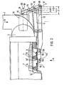
- FIG. 2 shows the blind as well as section II in FIG. 1b in the closed state. It also shows the first water tank 2 and the inlet 3 to this water tank, in which the coolant - here water - flows in the direction of arrow 6.
- the radiator blind comprises a fixed grille 7 and two sliding grids 9 and 10 which are movable with respect to this blind.
- the fixed grille 7 consists of slats, of which the two slats recognizable in FIG. 2 are designated 7a and 7b.
- These fins 7a and 7b are connected to the cooler 1 in a manner not shown. They have a streamlined profile, in this case approximately in the form of an approximate half ellipse, and are made of solid material, for example plastic or metal. They are also provided with lugs 7a 'and 7b', the function of which will be discussed in the following.
- the one sliding grille 9 consists of flat slats 9a and 9b and the second sliding grille 10 again consists of slats 10a and 10b with a streamlined profile.
- the lamellae 9a, 9b and 10a, 10b each of a grid are connected to each other at a distance, for example by longitudinal rods, not shown here, which run in the horizontal direction as shown in FIG. 2.
- Fig. 2 shows the radiator blind in the fully closed state.
- the slats of each sliding grille each cover approx. 33% of the cross-sectional area.
- a lever 11 is articulated on the sliding grille 9.
- a further lever 12 is likewise articulated on the second sliding grille 10.
- the second side of these levers is articulated on a rocker arm 13, namely on the same arm of this rocker arm, but at different distances from the bearing point 14 thereof.
- the second, opposite arm of this rocker arm 13 is acted upon by the piston rod 15 of the working piston, not shown here, of an expansion element 16.
- This expansion element 16 is arranged in the cooling water inlet and is therefore exposed to the temperature of the cooling water coming from the internal combustion engine.
- the working piston of the expansion element 16 and consequently also its piston rod is in the position shown.
- the sliding grids 9 and 10 are exposed to the force of a return spring (not shown here, to be explained with reference to FIG. 4), which press them into their closed position.
- a return spring not shown here, to be explained with reference to FIG. 4
- the lamellae of the first sliding grille in the illustration according to FIG. 3 were shifted to the left by a certain amount.
- This displacement path is designated by a in FIG. 2.
- the lamellae of the second sliding grille were displaced by a larger amount, since this grating is articulated on the rocker arm 13 at a greater distance from the bearing point 14 than the first sliding grille.
- the displacement path of the second sliding grille is denoted by b in FIG. 2.
- the piston rod 15 displaces the rocker arm 13 into its outermost position, indicated by the longitudinal center line 24.
- the piston rod is indicated by dashed lines in this position and designated by 25.
- the first sliding grille is thus shifted from the initial position by the path designated by c in FIG. 2 and the second sliding grille by the path d.
- the blind is now in its fully open position shown in FIG. 4.
- the lamellae of the fixed lattice are designated there with 26a to 26c and the lugs of these lamellae with 26a 'to 26c'. Accordingly, the slats of the first sliding grille bear the reference symbols 27a to 27c and the slats of the second sliding grille have the reference symbols 28a to 28c.
- the blind is now fully open with a theoretically free cross-sectional area of 66%.
- a profile with an approximately elliptical cross section is achieved, which has a very low flow resistance.
- the lugs 26a 'to 26c' form stops against which the lamellae 27a to 27c of the first sliding grille bear, so that the lamellae of all the grilles lie exactly one behind the other in the flow direction when the blind is fully open.
- dirt is deposited on the flowed surfaces of the slats 26, 27 and 28, which dirt is scraped off by the foremost edge of the surfaces sliding against one another when pushed together.
- the stop surfaces facing the slats 27 are provided with a wavy profile running in the longitudinal direction of the slats, so that the The front edge of the lamellae 27 abuts only on the points of the lugs 26a ', 26b' and 26c 'corresponding to the wave crests. The troughs then form dirt nests into which the deposits are pushed, which also results in a self-cleaning effect.
- a return spring 29, which is designed here as a compression spring and acts on the second sliding grille. Due to the joint articulation of the two sliding grilles on the rocker arm 13, only one of the two sliding grilles has to be acted upon by a spring. Of course, this could also be the first sliding grille.
- FIG. 4 also shows the second water tank 4 and the water outlet 5.
- the cooled cooling water flows in the direction of arrow 30.
- Rollers are provided for guiding the sliding grilles, which are mounted laterally on the slats of the fixed grille and the second sliding grille. Two of these roles are indicated schematically in FIG. 4 and designated 31 and 32. 6 shows a section through the lateral guide, a profiled guide rail being designated 33 and the roles of the fixed grille or the second sliding grille 34 and 35.
- the first sliding grille is designated 36 and runs with an edge 37 between the support rollers of the other two grids.
- FIG. 5 shows a schematic cross section through a further embodiment of the radiator blind.
- the slats of the fixed grille bear the reference symbols 38a and 38b, the slats of the first sliding grille the reference symbols 39a and 39b and the slats of the second sliding grille the reference symbol 40.
- the air flow direction, i. H. the flow towards the blind is indicated by arrow 41.
- the lugs are arranged on the grille facing the air flow.
- the nose of the lamella 40 bears the reference symbol 40 '. This arrangement of the nose has the advantage that when the sliding grids move in the edge 42 between the nose and the associated lamella, no dirt which is carried along by the air flow can settle.
- the slats 38a and 40 are designed here as a hollow profile made of metal.
- a fluid supply is connected to these hollow profiles.
- the blind can thus also be used as a cooling device for this fluid. Oil or steam to be condensed is preferably passed through these fins so that they can simultaneously take on the function of an oil cooler or a condenser.
- the hollow profiles can be provided with ribs, in particular on the outside.
Applications Claiming Priority (2)
| Application Number | Priority Date | Filing Date | Title |
|---|---|---|---|
| DE3438709A DE3438709C1 (de) | 1984-10-23 | 1984-10-23 | Kuehlerjalousie |
| DE3438709 | 1984-10-23 |
Publications (2)
| Publication Number | Publication Date |
|---|---|
| EP0179304A1 true EP0179304A1 (fr) | 1986-04-30 |
| EP0179304B1 EP0179304B1 (fr) | 1988-05-11 |
Family
ID=6248514
Family Applications (1)
| Application Number | Title | Priority Date | Filing Date |
|---|---|---|---|
| EP85112275A Expired EP0179304B1 (fr) | 1984-10-23 | 1985-09-27 | Calandre de radiateur |
Country Status (2)
| Country | Link |
|---|---|
| EP (1) | EP0179304B1 (fr) |
| DE (2) | DE3438709C1 (fr) |
Cited By (18)
| Publication number | Priority date | Publication date | Assignee | Title |
|---|---|---|---|---|
| EP0308601A2 (fr) * | 1987-09-23 | 1989-03-29 | Firma Carl Freudenberg | Jalousie |
| FR2687771A1 (fr) * | 1992-02-24 | 1993-08-27 | Valeo Thermique Moteur Sa | Dispositif de regulation du debit d'air traversant un echangeur de chaleur comportant un faisceau de tubes a ailettes et echangeur de chaleur equipe d'un tel dispositif. |
| EP0880003A3 (fr) * | 1997-05-23 | 1999-12-08 | Steyr-Daimler-Puch Aktiengesellschaft | Grille d'aération obturable pour véhicule blindé |
| EP1273467A1 (fr) * | 2001-02-13 | 2003-01-08 | Sanyo Electric Co., Ltd. | Climatisation de bord pour vehicule |
| WO2006034841A1 (fr) * | 2004-09-29 | 2006-04-06 | Decoma (Germany) Gmbh | Ensemble calandre de radiateur fermable pour vehicule automobile |
| EP2043885A1 (fr) * | 2006-07-20 | 2009-04-08 | Carrier Corporation | Chauffage ameliore pour unite de refrigeration de transport fonctionnant dans des conditions ambiantes froides |
| FR2930742A1 (fr) * | 2008-04-30 | 2009-11-06 | Peugeot Citroen Automobiles Sa | Dispositif de redirection d'un flux d'air |
| EP2172357A2 (fr) | 2008-10-01 | 2010-04-07 | Brose Fahrzeugteile GmbH & Co. KG, Würzburg | Dispositif de commande du débit d'air d'une entrée d'air |
| DE102009035086A1 (de) * | 2009-07-28 | 2011-02-10 | Behr Gmbh & Co. Kg | Wärmeübertrager |
| DE102010060253A1 (de) | 2010-10-29 | 2012-05-03 | Brose Fahrzeugteile Gmbh & Co. Kommanditgesellschaft, Coburg | Vorrichtung zur Einstellung einer Kühlluftzuströmung |
| DE102014002533B3 (de) * | 2014-02-21 | 2015-05-21 | Audi Ag | Vorrichtung zur Steuerung des Luftdurchsatzes durch eine Öffnung einer Fahrzeugbaugruppe |
| WO2015142582A1 (fr) * | 2014-03-20 | 2015-09-24 | Magna International Inc. | Aube creuse avec structure |
| CN110439668A (zh) * | 2019-08-26 | 2019-11-12 | 沈红瑛 | 一种新型汽车散热水箱 |
| DE102018130232B3 (de) * | 2018-11-29 | 2019-11-14 | Alfred-Wegener-Institut, Helmholtz-Zentrum für Polar- und Meeresforschung | Sortiervorrichtung für lebende Fische |
| FR3081125A1 (fr) * | 2018-05-18 | 2019-11-22 | Valeo Systemes Thermiques | Dispositif d'obturation d'entree d'air de face avant de vehicule automobile |
| CN112537197A (zh) * | 2020-12-15 | 2021-03-23 | 中国第一汽车股份有限公司 | 一种主动进气格栅的控制方法、装置、设备及存储介质 |
| EP3805031A1 (fr) | 2019-10-07 | 2021-04-14 | Motherson Innovations Company Limited | Composant de garniture d'un véhicule et véhicule comportant un tel composant de garniture |
| CN114025980A (zh) * | 2019-07-03 | 2022-02-08 | Hbpo 有限公司 | 用于关闭机动车冷却模块的装置 |
Families Citing this family (13)
| Publication number | Priority date | Publication date | Assignee | Title |
|---|---|---|---|---|
| DE19724728C2 (de) * | 1997-06-12 | 2003-01-30 | Modine Mfg Co | Kühleranordnung und luftgekühlter Kühler |
| US6354096B1 (en) * | 2000-10-20 | 2002-03-12 | Nicholas R. Siler | Vehicular cooling system |
| DE102008009152A1 (de) | 2008-02-14 | 2009-08-20 | Volkswagen Ag | Ladeluftkühler und Arbeitsverfahren eines solchen Ladeluftkühlers |
| DE102008013420A1 (de) * | 2008-03-10 | 2009-09-17 | Röchling Automotive AG & Co. KG | Luftdurchlassvorrichtung mit entlastender Federvorrichtung, insbesondere für ein Kraftfahrzeug |
| DE102009043064A1 (de) | 2008-09-26 | 2010-05-06 | Behr Gmbh & Co. Kg | Wärmeübertrager |
| DE102008043006A1 (de) | 2008-10-21 | 2010-04-22 | Robert Bosch Gmbh | Vorrichtung für einen Kühler eines Fahrzeuges mit einer Lamellenstruktur |
| DE102009035362A1 (de) | 2009-07-30 | 2011-02-03 | Röchling Automotive AG & Co. KG | Strömungsleitmechanismus für ein Kraftfahrzeug |
| NL2005697C2 (nl) | 2010-11-15 | 2012-05-16 | Mci Mirror Controls Int Nl Bv | Verstelinrichting voor luchtinlaat, werkwijze voor het verstellen van een luchtinlaat met een verstelinrichting, motorvoertuig voorzien van een luchtinlaat met een verstelinrichting. |
| NL2007162C2 (nl) | 2011-07-21 | 2013-01-22 | Mci Mirror Controls Int Nl Bv | Verstelinrichting met aandrijfeenheid; luchtinlaat met een dergelijke verstelinrichting; motorvoertuig met een dergelijke luchtinlaat. |
| NL2008990C2 (nl) | 2012-06-12 | 2013-12-16 | Mci Mirror Controls Int Nl Bv | Verstelinrichting en werkwijze voor het verstellen van afsluitelementen. |
| NL2009105C2 (nl) | 2012-07-02 | 2014-01-06 | Mci Mirror Controls Int Nl Bv | Verstelsysteem, primaire versteleenheid en secundaire versteleenheid. |
| DE102015107551A1 (de) * | 2015-05-13 | 2016-11-17 | Hbpo Gmbh | Verschlussvorrichtung |
| DE102015109698B4 (de) | 2015-06-17 | 2021-06-24 | Hbpo Gmbh | Kühlsystem für ein Fahrzeug |
Citations (3)
| Publication number | Priority date | Publication date | Assignee | Title |
|---|---|---|---|---|
| DE613939C (de) * | 1932-08-20 | 1935-05-29 | Dora M Kaulen Geb Wenig | Loser, an der Stirnseite eines Kraftwagenkuehlers zu befestigender oder in den Kuehlermantel einzupassender Vorsatzrahmen mit Steinschlagschutzstaeben |
| DE7421585U (de) * | 1974-11-28 | Kratzmeier E | Kühlerabdeckvorrichtung für Kraftfahrzeuge | |
| DE7716940U1 (de) * | 1977-05-27 | 1979-02-22 | Kratzmeier, Ewald, 8060 Dachau | Kuehlerabdeckvorrichtung fuer brennkraftmaschinen, insbesondere von kraftfahrzeugen |
-
1984
- 1984-10-23 DE DE3438709A patent/DE3438709C1/de not_active Expired
-
1985
- 1985-09-27 EP EP85112275A patent/EP0179304B1/fr not_active Expired
- 1985-09-27 DE DE8585112275T patent/DE3562588D1/de not_active Expired
Patent Citations (3)
| Publication number | Priority date | Publication date | Assignee | Title |
|---|---|---|---|---|
| DE7421585U (de) * | 1974-11-28 | Kratzmeier E | Kühlerabdeckvorrichtung für Kraftfahrzeuge | |
| DE613939C (de) * | 1932-08-20 | 1935-05-29 | Dora M Kaulen Geb Wenig | Loser, an der Stirnseite eines Kraftwagenkuehlers zu befestigender oder in den Kuehlermantel einzupassender Vorsatzrahmen mit Steinschlagschutzstaeben |
| DE7716940U1 (de) * | 1977-05-27 | 1979-02-22 | Kratzmeier, Ewald, 8060 Dachau | Kuehlerabdeckvorrichtung fuer brennkraftmaschinen, insbesondere von kraftfahrzeugen |
Cited By (31)
| Publication number | Priority date | Publication date | Assignee | Title |
|---|---|---|---|---|
| EP0308601A3 (en) * | 1987-09-23 | 1989-09-27 | Firma Carl Freudenberg | Blind |
| EP0308601A2 (fr) * | 1987-09-23 | 1989-03-29 | Firma Carl Freudenberg | Jalousie |
| FR2687771A1 (fr) * | 1992-02-24 | 1993-08-27 | Valeo Thermique Moteur Sa | Dispositif de regulation du debit d'air traversant un echangeur de chaleur comportant un faisceau de tubes a ailettes et echangeur de chaleur equipe d'un tel dispositif. |
| EP0558384A1 (fr) * | 1992-02-24 | 1993-09-01 | Valeo Thermique Moteur | Dispositif de régulation du débit d'air traversant un échangeur de chaleur comportant un faisceau de tube à ailettes et échangeur de chaleur équipé d'un tel dispositif |
| EP0880003A3 (fr) * | 1997-05-23 | 1999-12-08 | Steyr-Daimler-Puch Aktiengesellschaft | Grille d'aération obturable pour véhicule blindé |
| US7066245B2 (en) | 2001-02-13 | 2006-06-27 | Sanyo Electric Co., Ltd. | On-vehicle air-conditioner for air-conditioning |
| EP1273467A1 (fr) * | 2001-02-13 | 2003-01-08 | Sanyo Electric Co., Ltd. | Climatisation de bord pour vehicule |
| EP1273467A4 (fr) * | 2001-02-13 | 2004-09-29 | Sanyo Electric Co | Climatisation de bord pour vehicule |
| US7717208B2 (en) | 2004-09-29 | 2010-05-18 | Decoma (Germany) Gmbh | Closeable motor vehicle radiator grill arrangement |
| WO2006034841A1 (fr) * | 2004-09-29 | 2006-04-06 | Decoma (Germany) Gmbh | Ensemble calandre de radiateur fermable pour vehicule automobile |
| EP2043885A1 (fr) * | 2006-07-20 | 2009-04-08 | Carrier Corporation | Chauffage ameliore pour unite de refrigeration de transport fonctionnant dans des conditions ambiantes froides |
| EP2043885A4 (fr) * | 2006-07-20 | 2010-06-16 | Carrier Corp | Chauffage ameliore pour unite de refrigeration de transport fonctionnant dans des conditions ambiantes froides |
| FR2930742A1 (fr) * | 2008-04-30 | 2009-11-06 | Peugeot Citroen Automobiles Sa | Dispositif de redirection d'un flux d'air |
| EP2172357A2 (fr) | 2008-10-01 | 2010-04-07 | Brose Fahrzeugteile GmbH & Co. KG, Würzburg | Dispositif de commande du débit d'air d'une entrée d'air |
| DE102008049876A1 (de) | 2008-10-01 | 2010-04-08 | Brose Fahrzeugteile GmbH & Co. Kommanditgesellschaft, Würzburg | Vorrichtung zur Steuerung des Luftdurchsatzes eines Lufteinlasses |
| EP2172357A3 (fr) * | 2008-10-01 | 2010-04-28 | Brose Fahrzeugteile GmbH & Co. KG, Würzburg | Dispositif de commande du débit d'air d'une entrée d'air |
| DE102009035086A1 (de) * | 2009-07-28 | 2011-02-10 | Behr Gmbh & Co. Kg | Wärmeübertrager |
| DE102010060253A1 (de) | 2010-10-29 | 2012-05-03 | Brose Fahrzeugteile Gmbh & Co. Kommanditgesellschaft, Coburg | Vorrichtung zur Einstellung einer Kühlluftzuströmung |
| DE102014002533B3 (de) * | 2014-02-21 | 2015-05-21 | Audi Ag | Vorrichtung zur Steuerung des Luftdurchsatzes durch eine Öffnung einer Fahrzeugbaugruppe |
| WO2015142582A1 (fr) * | 2014-03-20 | 2015-09-24 | Magna International Inc. | Aube creuse avec structure |
| CN106103169A (zh) * | 2014-03-20 | 2016-11-09 | 麦格纳国际公司 | 中空叶片结构 |
| US9845003B2 (en) | 2014-03-20 | 2017-12-19 | Magna International Inc. | Hollow vane with structure |
| CN106103169B (zh) * | 2014-03-20 | 2019-10-18 | 麦格纳国际公司 | 中空叶片结构 |
| FR3081125A1 (fr) * | 2018-05-18 | 2019-11-22 | Valeo Systemes Thermiques | Dispositif d'obturation d'entree d'air de face avant de vehicule automobile |
| DE102018130232B3 (de) * | 2018-11-29 | 2019-11-14 | Alfred-Wegener-Institut, Helmholtz-Zentrum für Polar- und Meeresforschung | Sortiervorrichtung für lebende Fische |
| WO2020108690A1 (fr) | 2018-11-29 | 2020-06-04 | Alfred-Wegener-Institut, Helmholtz-Zentrum für Polar- und Meeresforschung | Dispositif de triage de poissons vivants |
| CN114025980A (zh) * | 2019-07-03 | 2022-02-08 | Hbpo 有限公司 | 用于关闭机动车冷却模块的装置 |
| CN110439668A (zh) * | 2019-08-26 | 2019-11-12 | 沈红瑛 | 一种新型汽车散热水箱 |
| EP3805031A1 (fr) | 2019-10-07 | 2021-04-14 | Motherson Innovations Company Limited | Composant de garniture d'un véhicule et véhicule comportant un tel composant de garniture |
| CN112537197A (zh) * | 2020-12-15 | 2021-03-23 | 中国第一汽车股份有限公司 | 一种主动进气格栅的控制方法、装置、设备及存储介质 |
| CN112537197B (zh) * | 2020-12-15 | 2022-02-22 | 中国第一汽车股份有限公司 | 一种主动进气格栅的控制方法、装置、设备及存储介质 |
Also Published As
| Publication number | Publication date |
|---|---|
| DE3562588D1 (en) | 1988-06-16 |
| EP0179304B1 (fr) | 1988-05-11 |
| DE3438709C1 (de) | 1986-04-30 |
Similar Documents
| Publication | Publication Date | Title |
|---|---|---|
| EP0179304B1 (fr) | Calandre de radiateur | |
| DE3151435C2 (de) | Kühlergrill für Kraftfahrzeuge | |
| EP0740617B1 (fr) | Systeme de chauffage et/ou de climatisation | |
| EP0308601B1 (fr) | Jalousie | |
| DE2835014C2 (fr) | ||
| DE2846076A1 (de) | Mediumablenkvorrichtung, vorzugsweise fuer den aus einem klimageraet austretenden luftstrom | |
| DE2638481C3 (de) | Verdampfer für eine Klimaanlage | |
| EP0318885A2 (fr) | Echangeur de chaleur, notamment refroidisseur pour moteur de véhicule | |
| DE2317086B2 (de) | Tür o.dgl. aus mehreren teleskopartig verschiebbaren Elementen | |
| DE2153743B2 (de) | Luftdüse für eine Belüftungsanlage | |
| DE102017118450A1 (de) | Luftausströmer für ein Fahrzeug | |
| EP1270286B1 (fr) | Dispositif pour diriger l'air, notamment pour un véhicule | |
| EP2602137B1 (fr) | Dispositif de sortie d'air pour l'espace intérieur d'un véhicule automobile | |
| DE102015012965A1 (de) | Vorrichtung zur Regulierung eines Luftstroms | |
| DE102005011814A1 (de) | Kühlerbaugruppe mit Vorrichtung zur Beeinflussung der durchströmbaren Luftmenge | |
| DE102018109985B4 (de) | Verschlussvorrichtung mit Leitschaufel | |
| EP0008779B1 (fr) | Dispositif de sortie d'air pour l'aération de pièces | |
| EP0554960A1 (fr) | Grille d'aération | |
| DE3901304C2 (fr) | ||
| DE102019108740A1 (de) | Ausströmer für ein Kraftfahrzeug | |
| EP3453545A1 (fr) | Diffuseur d'air pour habitacles de véhicules | |
| DE1580939C3 (de) | Lüftungsgitter für Fahrzeuge, insbesondere für Schienenfahrzeuge | |
| DE202005020989U1 (de) | Kühlerbaugruppe mit Vorrichtung zur Beeinflussung der durchströmbaren Luftmenge | |
| DE10297534B4 (de) | Abdeckung für einen Kühler | |
| DE2207514C2 (de) | Langgestreckte Luftaustrittsvorrichtung mit verstellbaren Ausblasöffnungen |
Legal Events
| Date | Code | Title | Description |
|---|---|---|---|
| PUAI | Public reference made under article 153(3) epc to a published international application that has entered the european phase |
Free format text: ORIGINAL CODE: 0009012 |
|
| AK | Designated contracting states |
Kind code of ref document: A1 Designated state(s): DE FR GB IT SE |
|
| 17P | Request for examination filed |
Effective date: 19860520 |
|
| 17Q | First examination report despatched |
Effective date: 19870211 |
|
| GRAA | (expected) grant |
Free format text: ORIGINAL CODE: 0009210 |
|
| AK | Designated contracting states |
Kind code of ref document: B1 Designated state(s): DE FR GB IT SE |
|
| ITF | It: translation for a ep patent filed |
Owner name: JACOBACCI & PERANI S.P.A. |
|
| GBT | Gb: translation of ep patent filed (gb section 77(6)(a)/1977) | ||
| REF | Corresponds to: |
Ref document number: 3562588 Country of ref document: DE Date of ref document: 19880616 |
|
| ET | Fr: translation filed | ||
| PLBE | No opposition filed within time limit |
Free format text: ORIGINAL CODE: 0009261 |
|
| STAA | Information on the status of an ep patent application or granted ep patent |
Free format text: STATUS: NO OPPOSITION FILED WITHIN TIME LIMIT |
|
| 26N | No opposition filed | ||
| PGFP | Annual fee paid to national office [announced via postgrant information from national office to epo] |
Ref country code: SE Payment date: 19920721 Year of fee payment: 8 |
|
| PGFP | Annual fee paid to national office [announced via postgrant information from national office to epo] |
Ref country code: FR Payment date: 19920730 Year of fee payment: 8 |
|
| PGFP | Annual fee paid to national office [announced via postgrant information from national office to epo] |
Ref country code: GB Payment date: 19920825 Year of fee payment: 8 |
|
| ITTA | It: last paid annual fee | ||
| PGFP | Annual fee paid to national office [announced via postgrant information from national office to epo] |
Ref country code: DE Payment date: 19920930 Year of fee payment: 8 |
|
| PG25 | Lapsed in a contracting state [announced via postgrant information from national office to epo] |
Ref country code: GB Effective date: 19930927 |
|
| PG25 | Lapsed in a contracting state [announced via postgrant information from national office to epo] |
Ref country code: SE Effective date: 19930928 |
|
| GBPC | Gb: european patent ceased through non-payment of renewal fee |
Effective date: 19930927 |
|
| PG25 | Lapsed in a contracting state [announced via postgrant information from national office to epo] |
Ref country code: FR Free format text: LAPSE BECAUSE OF NON-PAYMENT OF DUE FEES Effective date: 19940531 |
|
| PG25 | Lapsed in a contracting state [announced via postgrant information from national office to epo] |
Ref country code: DE Effective date: 19940601 |
|
| REG | Reference to a national code |
Ref country code: FR Ref legal event code: ST |
|
| EUG | Se: european patent has lapsed |
Ref document number: 85112275.4 Effective date: 19940410 |