EP0179304A1 - Radiator shutter - Google Patents
Radiator shutter Download PDFInfo
- Publication number
- EP0179304A1 EP0179304A1 EP85112275A EP85112275A EP0179304A1 EP 0179304 A1 EP0179304 A1 EP 0179304A1 EP 85112275 A EP85112275 A EP 85112275A EP 85112275 A EP85112275 A EP 85112275A EP 0179304 A1 EP0179304 A1 EP 0179304A1
- Authority
- EP
- European Patent Office
- Prior art keywords
- sliding
- grille
- slats
- blind
- radiator
- Prior art date
- Legal status (The legal status is an assumption and is not a legal conclusion. Google has not performed a legal analysis and makes no representation as to the accuracy of the status listed.)
- Granted
Links
Images


Classifications
-
- F—MECHANICAL ENGINEERING; LIGHTING; HEATING; WEAPONS; BLASTING
- F01—MACHINES OR ENGINES IN GENERAL; ENGINE PLANTS IN GENERAL; STEAM ENGINES
- F01P—COOLING OF MACHINES OR ENGINES IN GENERAL; COOLING OF INTERNAL-COMBUSTION ENGINES
- F01P7/00—Controlling of coolant flow
- F01P7/02—Controlling of coolant flow the coolant being cooling-air
- F01P7/10—Controlling of coolant flow the coolant being cooling-air by throttling amount of air flowing through liquid-to-air heat exchangers
- F01P7/12—Controlling of coolant flow the coolant being cooling-air by throttling amount of air flowing through liquid-to-air heat exchangers by thermostatic control
-
- B—PERFORMING OPERATIONS; TRANSPORTING
- B60—VEHICLES IN GENERAL
- B60K—ARRANGEMENT OR MOUNTING OF PROPULSION UNITS OR OF TRANSMISSIONS IN VEHICLES; ARRANGEMENT OR MOUNTING OF PLURAL DIVERSE PRIME-MOVERS IN VEHICLES; AUXILIARY DRIVES FOR VEHICLES; INSTRUMENTATION OR DASHBOARDS FOR VEHICLES; ARRANGEMENTS IN CONNECTION WITH COOLING, AIR INTAKE, GAS EXHAUST OR FUEL SUPPLY OF PROPULSION UNITS IN VEHICLES
- B60K11/00—Arrangement in connection with cooling of propulsion units
- B60K11/02—Arrangement in connection with cooling of propulsion units with liquid cooling
- B60K11/04—Arrangement or mounting of radiators, radiator shutters, or radiator blinds
-
- B—PERFORMING OPERATIONS; TRANSPORTING
- B60—VEHICLES IN GENERAL
- B60K—ARRANGEMENT OR MOUNTING OF PROPULSION UNITS OR OF TRANSMISSIONS IN VEHICLES; ARRANGEMENT OR MOUNTING OF PLURAL DIVERSE PRIME-MOVERS IN VEHICLES; AUXILIARY DRIVES FOR VEHICLES; INSTRUMENTATION OR DASHBOARDS FOR VEHICLES; ARRANGEMENTS IN CONNECTION WITH COOLING, AIR INTAKE, GAS EXHAUST OR FUEL SUPPLY OF PROPULSION UNITS IN VEHICLES
- B60K11/00—Arrangement in connection with cooling of propulsion units
- B60K11/08—Air inlets for cooling; Shutters or blinds therefor
- B60K11/085—Air inlets for cooling; Shutters or blinds therefor with adjustable shutters or blinds
-
- Y—GENERAL TAGGING OF NEW TECHNOLOGICAL DEVELOPMENTS; GENERAL TAGGING OF CROSS-SECTIONAL TECHNOLOGIES SPANNING OVER SEVERAL SECTIONS OF THE IPC; TECHNICAL SUBJECTS COVERED BY FORMER USPC CROSS-REFERENCE ART COLLECTIONS [XRACs] AND DIGESTS
- Y02—TECHNOLOGIES OR APPLICATIONS FOR MITIGATION OR ADAPTATION AGAINST CLIMATE CHANGE
- Y02T—CLIMATE CHANGE MITIGATION TECHNOLOGIES RELATED TO TRANSPORTATION
- Y02T10/00—Road transport of goods or passengers
- Y02T10/80—Technologies aiming to reduce greenhouse gasses emissions common to all road transportation technologies
- Y02T10/88—Optimized components or subsystems, e.g. lighting, actively controlled glasses
Definitions
- the invention relates to a radiator blind for the radiator of motor vehicles driven by an internal combustion engine with a fixed grille arranged in the air flow and consisting of mutually spaced lamellae and a sliding grille movable transversely to the airflow, parallel to the stationary grille and perpendicular to the longitudinal direction of the slats also consists of mutually spaced slats, which can be moved together and which are in the open state of the blind in the air flow direction in front of or behind the slats of the fixed grille and which at least partially cover the spaces between the slats of the fixed grille in the closed state of the blind .
- Radiator blinds are known in several embodiments.
- a particularly simple embodiment is, for example, the so-called fabric blind.
- a cloth is partially or completely pulled in front of the cooler if the effect of the cooler is to be compensated for, for example at very low outside temperatures.
- the cloth blind has several disadvantages. This includes not only the imprecision of the intended regulation; the fabric blind is also subject to considerable wear and can flutter, especially at higher speeds. The fabric blind is therefore generally not suitable for fast-moving vehicles.
- rotatable slats are provided in front of the cooler.
- a more or less large air flow can pass through them and dissipate the cooler heat.
- the actuating forces for pivoting the slats are very large and also not proportional to the pivoting angle. If the slats are therefore in the partially open position, their position is not sufficiently stable so that precise regulation of the air flow cannot be achieved.
- rattling occurs in particular in the partially open position of the rotatable slats.
- a radiator blind of the type mentioned in the introduction in which a stationary grille and a sliding grille are provided.
- the slats are not rotatable and are firmly connected to their respective grids.
- the sliding grille By moving the sliding grille, the slats of the two grilles can be made to coincide, resulting in the fully open state of the blind, while in the closed state of the same, the sliding grille is shifted so that the slats of the two grilles alternately partially or completely cover the air flow .
- Such a sliding blind has the advantage that only small actuating forces are required to move the sliding grille and that the position of the sliding grille is stable. This results in a precisely meterable control in which no noise occurs.
- a disadvantage of this sliding blind is, however, that in the fully opened state of the same, the free cross-sectional area through which the air flow can pass is only 50% of the total cross-sectional area.
- the cooling air throughput and thus the effectiveness of the cooler is therefore severely limited, especially in modern cooler systems which have a free cross-sectional area of up to 75%.
- the result is insufficient cooling, especially in fast vehicles, when maximum heat dissipation in the cooler is required.
- a larger dimensioning of the cooler due to the con Structural design of the radiator blind is too expensive and expensive.
- the invention has set itself the task of designing a radiator blind of the type mentioned in such a way that in the maximally open state of the blind there is sufficient air throughput, but the advantages of the sliding blind are retained. '
- At least one further sliding grille which is movable in the same direction as the first sliding grille and also consists of slats which are connected to one another at a distance, is provided, the slats of which, in the open state of the blind, in the air flow direction with the slats of the stationary grille and the first Sliding grids are aligned, while in the fully closed state of the blind they partially cover the spaces between the slats of the fixed grille and the other part of these spaces are covered by the slats of the first sliding grille.
- the invention therefore provides that instead of a single sliding grate that can be moved relative to the stationary grating, a plurality of sliding grids are used.
- the lamellas of the various grilles lie one behind the other in the direction of air flow.
- the cross-sectional area that can be freely flowed through can therefore be increased as desired.
- using two movable sliding grids results in a maximum theoretical free cross-sectional area of 66%
- using three movable sliding grids results in a maximum theoretical free cross-sectional area of 75%.
- the cross-sectional area that can be freely flowed through can in principle be increased as desired without sacrificing the advantages of the sliding blind.
- the sliding blind can therefore also be used for applications in which it was previously not usable due to the maximum heat dissipation rate required, for example in fast-moving passenger vehicles.
- the sliding grids can each be moved via their own drives. If the application allows this, regulation of these drives can then be dispensed with, so that the sliding grids are now each moved to the "fully closed” or “fully open” position. Three positions of the blind are then possible: when the blind is closed, both sliding grilles are closed; only one sliding grille in the half-open state and none of the sliding grilles in the open state.
- both the first and the second and possibly the further sliding grids are articulated on a common drive element. This saves at least one drive.
- the sliding grilles are therefore adjusted together when the blind is continuously closed or opened.
- a lever is expediently provided as the drive element, on which these sliding grids are articulated - preferably via further levers - and on which an actuating element engages.
- the sliding grids are adjusted in opposite directions, they are articulated on different arms of the lever (ie arms opposite the bearing point).
- the sliding grilles are articulated on the same arm of the lever, but at different distances from the bearing point thereof. This results in an equal sensible adjustment of the sliding grille, the sliding grilles being moved by a different amount due to the different distances from the bearing point of the lever when a lever is pivoted.
- the slats of the one sliding grille are thus displaced by a smaller amount than the slats of the second sliding grille, so that the air flow can be completely interrupted.
- this also applies to a third, fourth, etc. sliding grille that may be provided.
- the lever is designed as a rocker arm and the actuating element engages on the lever arm opposite the articulation points of the sliding grids.
- the actuating element is thus articulated on one arm of the rocker arm, while the movable sliding grids are articulated on the other arm at different distances from the bearing point.
- the actuating element is connected to a handle, possibly via a deflection linkage or the like, by means of which the sliding grids can be manually closed or opened.
- the sliding grilles are opened / closed automatically, it is particularly advantageous if the actuating element is an expansion element filled with expansion material that expands when heated, which is located in the cooling water circuit, preferably in the cooler supply line or in the region of an upper water box connected to the supply of the cooler, is arranged, this expansion element having a working piston, the piston rod of which acts on the lever actuating the sliding grille.
- At least one return spring is also provided which engages one of the sliding grids.
- This return spring supports the movement of the sliding grids in one direction and thereby relieves the expansion element.
- the return spring is preferably installed so that it supports the closing of the sliding grids, i. H. the movement of the working piston when entering the expansion element. If the sliding grids are hinged to a common lever, a return spring is sufficient, since the movement of the further sliding grilles is also supported.
- the lamellae of the grille facing the air flow and / or the lamellae of the grille facing away from the air flow are profiled in a streamlined manner and in particular have a cross section approximating a half ellipse.
- the aerodynamic design results in a lower air resistance, so that the heat dissipation in the cooler is further improved.
- At least one lamella of at least one grid is designed as a hollow profile and that a fluid to be cooled, preferably oil or steam to be condensed, is passed through the cavity of this hollow profile.
- the radiator blind can thus also be used as an oil cooler or condenser.
- This design is particularly favorable if the lamellae of part of the grille have a flow profile. In this case, for reasons of material savings, it is expedient if the slats as Hollow profiles are executed, these hollow profiles then only to the fluid supply. Fluid drain must be connected.
- the slats of one of the outer grilles are preferably provided with a projecting nose, against which the slats of the other grilles rest when the blind is fully open. In this way, a stop is created in a simple manner, which ensures that the slats of the various gratings lie exactly one behind the other in the fully open state of the blind in the air flow direction. If the lugs are attached to the slats of the grille facing the air flow, the advantage is also achieved that no dust or dirt particles against these lugs when opening the blind and at the angle that the lugs with the slats to which they are attached , form, be pressed.
- the invention thus creates a radiator blind that is robust, low-maintenance, insensitive to cold and dirt and in which the application of air to a cooling fan is more uniform and thus less noisy than the known embodiments.
- the radiator blind can also be placed in front of and behind the radiator.
- FIGS. 1 a to 1 c show a motor vehicle radiator 1 designed as a cross flow cooler.
- a first water tank 2 the inlet 3 of which is designated, is connected to a second water tank 4 via pipes.
- the outlet of this second water tank 4 bears the reference number 5.
- the tubes are provided with fins in a manner not shown and customary, which serve for air guidance.
- a radiator blind is arranged in front of the actual radiator.
- the structure of this radiator blind is to be explained below with reference to FIGS. 2 to 4, which show an enlarged representation of the areas designated II to IV in FIG. 1b.
- FIGS. 2 to 4 show an enlarged representation of the areas designated II to IV in FIG. 1b.
- FIGS. 2 to 4 show an enlarged representation of the areas designated II to IV in FIG. 1b.
- FIGS. 2 to 4 show an enlarged representation of the areas designated II to IV in FIG. 1b.
- FIGS. 2 to 4 show an enlarged representation of the areas designated II to IV in FIG. 1b.
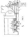
- FIG. 2 shows the blind as well as section II in FIG. 1b in the closed state. It also shows the first water tank 2 and the inlet 3 to this water tank, in which the coolant - here water - flows in the direction of arrow 6.
- the radiator blind comprises a fixed grille 7 and two sliding grids 9 and 10 which are movable with respect to this blind.
- the fixed grille 7 consists of slats, of which the two slats recognizable in FIG. 2 are designated 7a and 7b.
- These fins 7a and 7b are connected to the cooler 1 in a manner not shown. They have a streamlined profile, in this case approximately in the form of an approximate half ellipse, and are made of solid material, for example plastic or metal. They are also provided with lugs 7a 'and 7b', the function of which will be discussed in the following.
- the one sliding grille 9 consists of flat slats 9a and 9b and the second sliding grille 10 again consists of slats 10a and 10b with a streamlined profile.
- the lamellae 9a, 9b and 10a, 10b each of a grid are connected to each other at a distance, for example by longitudinal rods, not shown here, which run in the horizontal direction as shown in FIG. 2.
- Fig. 2 shows the radiator blind in the fully closed state.
- the slats of each sliding grille each cover approx. 33% of the cross-sectional area.
- a lever 11 is articulated on the sliding grille 9.
- a further lever 12 is likewise articulated on the second sliding grille 10.
- the second side of these levers is articulated on a rocker arm 13, namely on the same arm of this rocker arm, but at different distances from the bearing point 14 thereof.
- the second, opposite arm of this rocker arm 13 is acted upon by the piston rod 15 of the working piston, not shown here, of an expansion element 16.
- This expansion element 16 is arranged in the cooling water inlet and is therefore exposed to the temperature of the cooling water coming from the internal combustion engine.
- the working piston of the expansion element 16 and consequently also its piston rod is in the position shown.
- the sliding grids 9 and 10 are exposed to the force of a return spring (not shown here, to be explained with reference to FIG. 4), which press them into their closed position.
- a return spring not shown here, to be explained with reference to FIG. 4
- the lamellae of the first sliding grille in the illustration according to FIG. 3 were shifted to the left by a certain amount.
- This displacement path is designated by a in FIG. 2.
- the lamellae of the second sliding grille were displaced by a larger amount, since this grating is articulated on the rocker arm 13 at a greater distance from the bearing point 14 than the first sliding grille.
- the displacement path of the second sliding grille is denoted by b in FIG. 2.
- the piston rod 15 displaces the rocker arm 13 into its outermost position, indicated by the longitudinal center line 24.
- the piston rod is indicated by dashed lines in this position and designated by 25.
- the first sliding grille is thus shifted from the initial position by the path designated by c in FIG. 2 and the second sliding grille by the path d.
- the blind is now in its fully open position shown in FIG. 4.
- the lamellae of the fixed lattice are designated there with 26a to 26c and the lugs of these lamellae with 26a 'to 26c'. Accordingly, the slats of the first sliding grille bear the reference symbols 27a to 27c and the slats of the second sliding grille have the reference symbols 28a to 28c.
- the blind is now fully open with a theoretically free cross-sectional area of 66%.
- a profile with an approximately elliptical cross section is achieved, which has a very low flow resistance.
- the lugs 26a 'to 26c' form stops against which the lamellae 27a to 27c of the first sliding grille bear, so that the lamellae of all the grilles lie exactly one behind the other in the flow direction when the blind is fully open.
- dirt is deposited on the flowed surfaces of the slats 26, 27 and 28, which dirt is scraped off by the foremost edge of the surfaces sliding against one another when pushed together.
- the stop surfaces facing the slats 27 are provided with a wavy profile running in the longitudinal direction of the slats, so that the The front edge of the lamellae 27 abuts only on the points of the lugs 26a ', 26b' and 26c 'corresponding to the wave crests. The troughs then form dirt nests into which the deposits are pushed, which also results in a self-cleaning effect.
- a return spring 29, which is designed here as a compression spring and acts on the second sliding grille. Due to the joint articulation of the two sliding grilles on the rocker arm 13, only one of the two sliding grilles has to be acted upon by a spring. Of course, this could also be the first sliding grille.
- FIG. 4 also shows the second water tank 4 and the water outlet 5.
- the cooled cooling water flows in the direction of arrow 30.
- Rollers are provided for guiding the sliding grilles, which are mounted laterally on the slats of the fixed grille and the second sliding grille. Two of these roles are indicated schematically in FIG. 4 and designated 31 and 32. 6 shows a section through the lateral guide, a profiled guide rail being designated 33 and the roles of the fixed grille or the second sliding grille 34 and 35.
- the first sliding grille is designated 36 and runs with an edge 37 between the support rollers of the other two grids.
- FIG. 5 shows a schematic cross section through a further embodiment of the radiator blind.
- the slats of the fixed grille bear the reference symbols 38a and 38b, the slats of the first sliding grille the reference symbols 39a and 39b and the slats of the second sliding grille the reference symbol 40.
- the air flow direction, i. H. the flow towards the blind is indicated by arrow 41.
- the lugs are arranged on the grille facing the air flow.
- the nose of the lamella 40 bears the reference symbol 40 '. This arrangement of the nose has the advantage that when the sliding grids move in the edge 42 between the nose and the associated lamella, no dirt which is carried along by the air flow can settle.
- the slats 38a and 40 are designed here as a hollow profile made of metal.
- a fluid supply is connected to these hollow profiles.
- the blind can thus also be used as a cooling device for this fluid. Oil or steam to be condensed is preferably passed through these fins so that they can simultaneously take on the function of an oil cooler or a condenser.
- the hollow profiles can be provided with ribs, in particular on the outside.
Abstract
Description
Die Erfindung betrifft eine Kühlerjalousie für die Kühler von durch einen Verbrennungsmotor angetriebenen Kraftfahrzeugen mit einem im Luftstrom angeordneten ortsfesten, aus untereinander im Abstand verbundenen Lamellen bestehendes Gitter und einem quer zum Luftstrom, parallel zu dem ortsfesten Gitter und senkrecht zur Längsrichtung der Lamellen bewegbaren Schiebegitter, welches ebenfalls aus untereinander im Abstand verbundenen Lamellen besteht, die gemeinsam verschiebbar sind und die sich im geöffneten Zustand der Jalousie in Luftströmungsrichtung vor oder hinter den Lamellen des ortsfesten Gitters befinden und die im geschlossenen Zustand der Jalousie die Zwischenräume zwischen den Lamellen des ortsfesten Gitters wenigstens teilweise abdecken.The invention relates to a radiator blind for the radiator of motor vehicles driven by an internal combustion engine with a fixed grille arranged in the air flow and consisting of mutually spaced lamellae and a sliding grille movable transversely to the airflow, parallel to the stationary grille and perpendicular to the longitudinal direction of the slats also consists of mutually spaced slats, which can be moved together and which are in the open state of the blind in the air flow direction in front of or behind the slats of the fixed grille and which at least partially cover the spaces between the slats of the fixed grille in the closed state of the blind .
Kühlerjalousien sind in mehreren Ausführungsformen bekannt.Radiator blinds are known in several embodiments.
Eine besonders einfache Ausführungsform ist beispielsweise die sogenannte Tuchjalousie. Bei dieser Ausführungsform wird ein Tuch teilweise oder vollständig vor den Kühler gezogen, wenn die Wirkung des Kühlers kompensiert werden soll, beispielsweise bei sehr geringen Außentemperaturen. Die Tuchjalousie hat allerdings mehrere Nachteile. Hierzu gehört nicht nur die Ungenauigkeit der angestrebten Regelung; die Tuchjalousie ist darüber hinaus auch einem erheblichen Verschleiß ausgesetzt und kann insbesondere bei höheren Fahrtgeschwindigkeiten ins Flattern kommen. Für schnell fahrende Fahrzeuge ist die Tuchjalousie daher grundsätzlich nicht geeignet.A particularly simple embodiment is, for example, the so-called fabric blind. In this embodiment, a cloth is partially or completely pulled in front of the cooler if the effect of the cooler is to be compensated for, for example at very low outside temperatures. However, the cloth blind has several disadvantages. This includes not only the imprecision of the intended regulation; the fabric blind is also subject to considerable wear and can flutter, especially at higher speeds. The fabric blind is therefore generally not suitable for fast-moving vehicles.
Bei einer anderen, häufig verwendeten Jalousie sind vor dem Kühler angeordnete, drehbare Lamellen vorgesehen. Je nach dem Schwenkwinkel dieser Lamellen, die gemeinsam verstellbar sind, kann ein mehr oder weniger großer Luftstrom diese passieren und die Kühlerwärme abführen. Hier tritt jedoch der Nachteil auf, daß die Stellkräfte zum Verschwenken der Lamellen sehr groß sind und auch nicht proportional zum Verschwenkwinkel. Befinden sich die Lamellen daher in der teilweise geöffneten Stellung, so ist ihre Lage nicht ausreichend stabil, so daß eine genaue Regelung des Luftstromes nicht erreicht werden kann. Außerdem tritt insbesondere in der teilweise geöffneten Stellung der drehbaren Lamellen ein Klappern auf.In another, frequently used blind, rotatable slats are provided in front of the cooler. Depending on the swivel angle of these fins, which can be adjusted together, a more or less large air flow can pass through them and dissipate the cooler heat. Here, however, there is the disadvantage that the actuating forces for pivoting the slats are very large and also not proportional to the pivoting angle. If the slats are therefore in the partially open position, their position is not sufficiently stable so that precise regulation of the air flow cannot be achieved. In addition, rattling occurs in particular in the partially open position of the rotatable slats.
Diese Nachteile vermeidet eine Kühlerjalousie der eingangs genannten Art, bei der ein ortsfestes Gitter sowie ein Schiebegitter vorgesehen ist. Die Lamellen sind hierbei nicht drehbar und mit ihrem jeweiligen Gitter fest verbunden. Durch Verschieben des Schiebegitters können die Lamellen der beiden Gitter zur Deckung gebracht werden, wodurch sich der voll geöffnete Zustand der Jalousie ergibt, während im geschlossenen Zustand derselben das Schiebegitter so verschoben wird, daß die Lamellen der beiden Gitter jeweils abwechselnd den Luftstrom teilweise oder vollständig abdecken.These disadvantages are avoided by a radiator blind of the type mentioned in the introduction, in which a stationary grille and a sliding grille are provided. The slats are not rotatable and are firmly connected to their respective grids. By moving the sliding grille, the slats of the two grilles can be made to coincide, resulting in the fully open state of the blind, while in the closed state of the same, the sliding grille is shifted so that the slats of the two grilles alternately partially or completely cover the air flow .
Eine derartige Schiebejalousie hat den Vorteil, daß zur Bewegung des Schiebegitters nur kleine Stellkräfte erforderlich sind und daß die Lage des Schiebegitters stabil ist. Es ergibt sich somit eine genau dosierbare Regelung, bei der keine Geräuschbildung auftritt.Such a sliding blind has the advantage that only small actuating forces are required to move the sliding grille and that the position of the sliding grille is stable. This results in a precisely meterable control in which no noise occurs.
Nachteilig bei dieser Schiebejalousie ist jedoch, daß im voll geöffneten Zustand derselben die freie Querschnittsfläche, durch die der Luftstrom hindurchtreten kann, nur 50 % der gesamten Querschnittsfläche beträgt. Der Kühlluftdurchsatz und damit die Wirksamkeit des Kühlers ist daher insbesondere bei modernen Kühlersystemen, die eine freie Querschnittsfläche von bis zu 75 % aufweisen, stark beschränkt. Die Folge ist eine insbesondere bei schnellen Fahrzeugen nicht ausreichende Kühlung, wenn maximale Wärmeabfuhr im Kühler gefordert ist. Eine größere Dimensionierung des Kühlers allein aufgrund der konstruktiven Ausgestaltung der Kühlerjalousie ist zu kosten- und materialaufwendig.A disadvantage of this sliding blind is, however, that in the fully opened state of the same, the free cross-sectional area through which the air flow can pass is only 50% of the total cross-sectional area. The cooling air throughput and thus the effectiveness of the cooler is therefore severely limited, especially in modern cooler systems which have a free cross-sectional area of up to 75%. The result is insufficient cooling, especially in fast vehicles, when maximum heat dissipation in the cooler is required. A larger dimensioning of the cooler due to the con Structural design of the radiator blind is too expensive and expensive.
Die Erfindung hat sich die Aufgabe gestellt, eine Kühlerjalousie der eingangs genannten Art so auszubilden, daß im maximal geöffneten Zustand der Jalousie ein ausreichender Luftdurchsatz durch diese stattfindet, dennoch aber die Vorteile der Schiebejalousie erhalten bleiben. 'The invention has set itself the task of designing a radiator blind of the type mentioned in such a way that in the maximally open state of the blind there is sufficient air throughput, but the advantages of the sliding blind are retained. '
Diese Aufgabe wird dadurch gelöst, daß wenigstens ein weiteres, in derselben Richtung wie das erste Schiebegitter bewegbares und ebenfalls aus untereinander im Abstand verbundenen Lamellen bestehendes Schiebegitter vorgesehen ist, dessen Lamellen im geöffneten Zustand der Jalousie in Luftströmungsrichtung mit den Lamellen des ortsfesten Gitters und des ersten Schiebegitters fluchten, während sie im vollständig geschlossenen Zustand der Jalousie-die Zwischenräume zwischen den Lamellen des ortsfesten Gitters teilweise abdecken und der andere Teil dieser Zwischenräume von den Lamellen des ersten Schiebegitters abgedeckt wird.This object is achieved in that at least one further sliding grille, which is movable in the same direction as the first sliding grille and also consists of slats which are connected to one another at a distance, is provided, the slats of which, in the open state of the blind, in the air flow direction with the slats of the stationary grille and the first Sliding grids are aligned, while in the fully closed state of the blind they partially cover the spaces between the slats of the fixed grille and the other part of these spaces are covered by the slats of the first sliding grille.
Die Erfindung sieht also vor, daß statt eines einzigen, gegenüber dem ortsfesten Gitter bewegbaren Schiebegitters mehrere Schiebegitter verwendet werden. Im voll geöffneten Zustand der Kühlerjalousie liegen die Lamellen der verschiedenen Gitter in Luftströmungsrichtung hintereinander. Je nach der Anzahl der bewegbaren Schiebegitter läßt sich die frei durchströmbare Querschnittsfläche daher beliebig vergrößern. Beim Einsatz von zwei bewegbaren Schiebegittern ergibt sich beispielsweise eine maximale theoretische freie Querschnittsfläche von 66 %, während beim Einsatz von drei bewegbaren Schiebegittern eine maximale theoretische freie Querschnittsfläche von 75 % erreicht wird. Die frei durchströmbare Querschnittsfläche läßt sich so im Prinzip beliebig vergrößern, ohne daß auf die Vorteile der Schiebejalousie verzichtet wird. Die Schiebejalousie ist damit auch für Anwendungsfälle einsetzbar, in denen sie bisher aufgrund der geforderten maximalen Wärmeabfuhrrate nicht verwendbar war, beispielsweise bei schnell fahrenden Personenfahrzeugen.The invention therefore provides that instead of a single sliding grate that can be moved relative to the stationary grating, a plurality of sliding grids are used. When the radiator blind is fully open, the lamellas of the various grilles lie one behind the other in the direction of air flow. Depending on the number of movable sliding grilles, the cross-sectional area that can be freely flowed through can therefore be increased as desired. For example, using two movable sliding grids results in a maximum theoretical free cross-sectional area of 66%, while using three movable sliding grids results in a maximum theoretical free cross-sectional area of 75%. The cross-sectional area that can be freely flowed through can in principle be increased as desired without sacrificing the advantages of the sliding blind. The sliding blind can therefore also be used for applications in which it was previously not usable due to the maximum heat dissipation rate required, for example in fast-moving passenger vehicles.
Bevorzugt - da in den meisten Anwendungsfällen ausreichend - werden außer dem ortsfesten Gitter zwei Schiebegitter eingesetzt.Preferred - since sufficient in most applications - two sliding grids are used in addition to the fixed grille.
In einer Ausführungsform sind die Schiebegitter jeweils über eigene Antriebe bewegbar. Wenn der Anwendungsfall dies zuläßt, kann dann auf eine Regelung dieser Antriebe verzichtet werden, so daß die Schiebegitter jeweils nun in die Stellung "voll geschlossen" bzw. "voll geöffnet" gefahren werden. Es sind dann drei Stellungen der Jalousie möglich: Im geschlossenen Zustand der Jalousie sind beide Schiebegitter geschlossen; im halbge- öffneten Zustand nur ein Schiebegitter und im geöffneten Zustand keines der Schiebegitter.In one embodiment, the sliding grids can each be moved via their own drives. If the application allows this, regulation of these drives can then be dispensed with, so that the sliding grids are now each moved to the "fully closed" or "fully open" position. Three positions of the blind are then possible: when the blind is closed, both sliding grilles are closed; only one sliding grille in the half-open state and none of the sliding grilles in the open state.
Falls dagegen eine kontinuierliche Regelung der Kühlerjalousie gewünscht wird, ist es vorteilhaft, wenn sowohl das erste als auch das zweite und ggf. die weiteren Schiebegitter an einem gemeinsamen Antriebselement angelenkt sind. Hierdurch wird mindestens ein Antrieb eingespart. Beim kontinuierlichen Schließen bzw. öffnen der Jalousie werden die Schiebegitter daher gemeinsam verstellt. Als Antriebselement ist zweckmäßig ein Hebel vorgesehen, an dem diese Schiebegitter - vorzugsweise über weitere Hebel - angelenkt sind und an dem ein Betätigungselement angreift.If, on the other hand, continuous control of the radiator blind is desired, it is advantageous if both the first and the second and possibly the further sliding grids are articulated on a common drive element. This saves at least one drive. The sliding grilles are therefore adjusted together when the blind is continuously closed or opened. A lever is expediently provided as the drive element, on which these sliding grids are articulated - preferably via further levers - and on which an actuating element engages.
Bei gegensinniger Verstellung der Schiebegitter sind diese an verschiedenen Armen des Hebels (d. h. bezüglich des Lagerpunktes gegenüberliegenden Armen) angelenkt. Aus Einbaugründen, insbesondere im Hinblick auf einen raumsparenden Einbau, ist es jedoch auch vorteilhaft, wenn die Schiebegitter an demselben Arm des Hebels, aber mit verschiedenen Abständen zum Lagerpunkt desselben, angelenkt sind. Hierdurch ergibt sich eine gleichsinnige Verstellung der Schiebegitter, wobei infolge der verschiedenen Abstände zum Lagerpunkt des Hebels die Schiebegitter bei einer Schwenkbewegung eines Hebels um einen unterschiedlichen Betrag verschoben werden. Die Lamellen des einen Schiebegitters werden also um einen geringeren Betrag verschoben als die Lamellen des zweiten Schiebegitters, so daß die Luftströmung vollständig unterbrochen werden kann. Dies gilt natürlich auch für ein eventuell vorgesehenes drittes, viertes etc. Schiebegitter.If the sliding grids are adjusted in opposite directions, they are articulated on different arms of the lever (ie arms opposite the bearing point). For reasons of installation, in particular with regard to a space-saving installation, it is also advantageous if the sliding grilles are articulated on the same arm of the lever, but at different distances from the bearing point thereof. This results in an equal sensible adjustment of the sliding grille, the sliding grilles being moved by a different amount due to the different distances from the bearing point of the lever when a lever is pivoted. The slats of the one sliding grille are thus displaced by a smaller amount than the slats of the second sliding grille, so that the air flow can be completely interrupted. Of course, this also applies to a third, fourth, etc. sliding grille that may be provided.
Hierbei ergibt sich eine besonders günstige Einbaumöglichkeit, wenn der Hebel als Kipphebel ausgebildet ist und das Betätigungselement an dem den Anlenkpunkten der Schiebegitter gegenüberliegenden Hebelarm angreift. An einem Arm des Kipphebels ist bei dieser Ausführungsform also das Betätigungselement angelenkt, während an dem anderen Arm mit verschiedenen Abständen zum Lagerpunkt die beweglichen Schiebegitter angelenkt sind.This results in a particularly favorable installation option if the lever is designed as a rocker arm and the actuating element engages on the lever arm opposite the articulation points of the sliding grids. In this embodiment, the actuating element is thus articulated on one arm of the rocker arm, while the movable sliding grids are articulated on the other arm at different distances from the bearing point.
In einer einfachen Ausführungsform ist das Betätigungselement, ggf. über ein Umlenkgestänge o. dgl., mit einem Handgriff verbunden, über den die Schiebegitter manuell geschlossen oder geöffnet werden können. Soll das öffnen/Schließen der Schiebegitter hingegen automatisch erfolgen, so ist es besonders vorteilhaft, wenn das Betätigungselement ein mit sich bei Erwärmung ausdehnendem Dehnstoff gefülltes Dehnstoffelement ist, welches im Kühlwasserkreislauf, vorzugsweise in der Kühlerzuleitung oder im Bereich eines oberen, an den Zulauf angeschlossenen Wasserkastens des Kühlers, angeordnet ist, wobei dieses Dehnstoffelement einen Arbeitskolben aufweist, dessen Kolbenstange an dem die Schiebegitter betätigenden Hebel angreift. Mit einem derartigen Dehnstoffelement, das in den Kühler ein-oder an diesen angebaut werden kann, ist eine einfache, stufenlose Regelung der Kühlerjalousie möglich. Bei Erwärmung dehnt sich der Dehnstoff, mit dem das Dehnstoffelement gefüllt ist, aus und bewirkt ein mehr oder weniger starkes öffnen der Schiebegitter. Umgekehrt verläuft der Vorgang bei der Abkühlung des Dehnstoffs. Diese sehr einfache Anordnung gewährleistet eine zuverlässige und von der Kühlwassertemperatur gesteuerte Bedienung der Kühlerjalousie.In a simple embodiment, the actuating element is connected to a handle, possibly via a deflection linkage or the like, by means of which the sliding grids can be manually closed or opened. If, on the other hand, the sliding grilles are opened / closed automatically, it is particularly advantageous if the actuating element is an expansion element filled with expansion material that expands when heated, which is located in the cooling water circuit, preferably in the cooler supply line or in the region of an upper water box connected to the supply of the cooler, is arranged, this expansion element having a working piston, the piston rod of which acts on the lever actuating the sliding grille. With such an expansion element, which can be built into or attached to the cooler, a simple, stepless regulation of the radiator blind is possible. When heated, the expansion material with which the expansion element is filled expands and causes the sliding grids to open to a greater or lesser extent. The reverse is true for cooling of the expansion material. This very simple arrangement ensures reliable operation of the radiator blind, which is controlled by the cooling water temperature.
In zweckmäßiger Weiterbildung ist ferner mindestens eine Rückholfeder vorgesehen, die an einem der Schiebegitter angreift.. Diese Rückholfeder unterstützt die Bewegung der Schiebegitter in einer Richtung und entlastet hierdurch das Dehnstoffelement. Bevorzugt wird die Rückholfeder so eingebaut, daß sie das Schließen der Schiebegitter unterstützt, d. h. die Bewegung des Arbeitskolbens beim Einfahren in das Dehnstoffelement. Wenn die Schiebegitter an einem gemeinsamen Hebel angelenkt sind, so genügt eine Rückholfeder, da die Bewegung der weiteren Schiebegitter zwangsweise mit unterstützt wird.In an expedient development, at least one return spring is also provided which engages one of the sliding grids. This return spring supports the movement of the sliding grids in one direction and thereby relieves the expansion element. The return spring is preferably installed so that it supports the closing of the sliding grids, i. H. the movement of the working piston when entering the expansion element. If the sliding grids are hinged to a common lever, a return spring is sufficient, since the movement of the further sliding grilles is also supported.
Die Verwendung eines Dehnstoffelements hat überdies den Vorteil, daß im Vergleich mit bekannten Ausführungsformen eine stoßsichere Regelung möglich ist.The use of an expansion element also has the advantage that a shockproof control is possible in comparison with known embodiments.
In einer vorteilhaften Ausführungsform sind die Lamellen des dem Luftstrom zugewandten Gitters und/oder die Lamellen des dem Luftstrom abgewandten Gitters strömungsgünstig profiliert und besitzen insbesondere einen einer halben Ellipse angenäherten Querschnitt. Durch die strömungsgünstige Ausbildung wird ein geringerer Luftwiderstand erzielt, so daß die Wärmeabfuhr im Kühler weiter verbessert wird.In an advantageous embodiment, the lamellae of the grille facing the air flow and / or the lamellae of the grille facing away from the air flow are profiled in a streamlined manner and in particular have a cross section approximating a half ellipse. The aerodynamic design results in a lower air resistance, so that the heat dissipation in the cooler is further improved.
Eine vorteilhafte Weiterbildung der Erfindung sieht vor, daß wenigstens eine Lamelle mindestens eines Gitters als Hohlprofil ausgeführt ist und daß durch den Hohlraum dieses Hohlprofils ein zu kühlendes Fluid, vorzugsweise öl oder zu kondensierender Dampf, geführt wird. Die Kühlerjalousie kann damit gleichzeitig als ölkühler oder Kondensator verwendet werden. Besonders günstig ist diese Ausführung, wenn die Lamellen eines Teils der Gitter ein Strömungsprofil aufweisen. Aus Materialersparnisgründen ist es in diesem Fall zweckmäßig, wenn die Lamellen als Hohlprofile ausgeführt werden, wobei diese Hohlprofile dann nur noch an die Fluidzuführung bwz. Fluidabfühung angeschlossen werden müssen.An advantageous development of the invention provides that at least one lamella of at least one grid is designed as a hollow profile and that a fluid to be cooled, preferably oil or steam to be condensed, is passed through the cavity of this hollow profile. The radiator blind can thus also be used as an oil cooler or condenser. This design is particularly favorable if the lamellae of part of the grille have a flow profile. In this case, for reasons of material savings, it is expedient if the slats as Hollow profiles are executed, these hollow profiles then only to the fluid supply. Fluid drain must be connected.
Bevorzugt sind die Lamellen eines der außenliegenden Gitter mit einer vorspringenden Nase versehen, an der sich die Lamellen der anderen Gitter im voll geöffneten Zustand der Jalousie anlegen. Hierdurch wird in einfacher Weise ein Anschlag geschaffen, der gewährleistet, daß die Lamellen der verschiedenen Gitter im voll geöffneten Zustand der Jalousie in Luftströmungsrichtung exakt hintereinander liegen. Wenn die Nasen an den Lamellen des dem Luftstrom zugewandten Gitters angebracht sind, wird überdies der Vorteil erzielt, daß beim öffnen der Jalousie keine Staub- oder Schmutzteilchen gegen diese Nasen und in den Winkel, den die Nasen mit den Lamellen, an denen sie angebracht sind, bilden, angepreßt werden.The slats of one of the outer grilles are preferably provided with a projecting nose, against which the slats of the other grilles rest when the blind is fully open. In this way, a stop is created in a simple manner, which ensures that the slats of the various gratings lie exactly one behind the other in the fully open state of the blind in the air flow direction. If the lugs are attached to the slats of the grille facing the air flow, the advantage is also achieved that no dust or dirt particles against these lugs when opening the blind and at the angle that the lugs with the slats to which they are attached , form, be pressed.
Die Erfindung schafft somit eine Kühlerjalousie, die robust, wartungsarm, kälte- und schmutzunempfindlich ist und bei der die Beaufschlagung eines Kühlgebläses mit Luft gegenüber den bekannten Ausführungsformen gleichmäßiger und damit geräuschärmer ist. Die Kühlerjalousie kann außerdem sowohl vor als auch hinter dem Kühler angeordnet werden.The invention thus creates a radiator blind that is robust, low-maintenance, insensitive to cold and dirt and in which the application of air to a cooling fan is more uniform and thus less noisy than the known embodiments. The radiator blind can also be placed in front of and behind the radiator.
Weitere Merkmale und Vorteile ergeben sich aus den Unteransprüchen sowie aus der Beschreibung zur Zeichnung, in der eine bevorzugte Ausführungsform der Erfindung dargestellt ist. Es zeigen:
- Fig. la die Frontansicht eines mit einer erfindungsgemäßen Kühlerjalousie versehenen Kraftfahrzeugkühlers,
- Fig. lb die teilweise geschnittene Seitenansicht dieses Kühlers,
- Fig. lc die Ansicht dieses Kühlers von oben,
- Fig. 2 die Einzelheit II der Fig. lb in vergrößerter Darstellung,
- Fig. 3 die Einzelheit III der Fig. lb in vergrößerter Darstellung,
- Fig. 4 die Einzelheit IV der Fig. lb in vergrößerter Darstellung,
- Fig. 5 einen Querschnitt durch eine Kühlerjalousie in einer anderen Ausführungsform und
- Fig. 6 die Führung eines beweglichen Gitters.
- La the front view of a motor vehicle radiator provided with a radiator blind according to the invention,
- Lb is a partially sectioned side view of this cooler,
- Lc the view of this cooler from above,
- 2 shows the detail II of FIG. 1b in an enlarged view,
- 3 shows detail III of FIG. 1b in an enlarged view,
- 4 shows the detail IV of FIG. 1b in an enlarged view,
- Fig. 5 shows a cross section through a radiator blind in another embodiment and
- Fig. 6, the leadership of a movable grid.
In den Fig. la bis lc ist ein als Querstromkühler ausgebildeter Kraftfahrzeugkühler 1 gezeigt. Bei diesem Kühler ist ein erster Wasserkasten 2, dessen Zulauf 3 bezeichnet ist, über Rohre mit einem zweiten Wasserkasten 4 verbunden. Der Auslauf dieses zweiten Wasserkastens 4 trägt das Bezugszeichen 5. Die Rohre sind in hier nicht gezeigter und üblicher Weise mit Lamellen versehen, die zur Luftführung dienen.FIGS. 1 a to 1 c show a
Vor dem eigentlichen Kühler ist eine Kühlerjalousie angeordnet. Der Aufbau dieser Kühlerjalousie soll im folgenden anhand der Fig. 2 bis 4, die vergrößerte Darstellung der in der Fig. lb mit II bis IV bezeichneten Bereiche zeigen, erläutert werden. An dieser Stelle ist darauf hinzuweisen, daß die in der Fig. 1b . gezeigten Schnitte II bis IV nicht die physikalische Realität zeigen. Im Abschnitt II befindet sich die Jalousie in der vollständig geschlossenen Stellung, während sie im Abschnitt III teilweise und im Abschnitt IV vollständig geöffnet ist. In Wirklichkeit zeigen jedoch die Bereiche II, III und IV stets dasselbe Bild, d. h. wenn die Jalousie im Bereich II ganz geschlossen ist, so ist sie dies auch in den Bereichen III und IV. Dasselbe gilt natürlich auch bei teilweise oder vollständig geöffneter Jalousie. Die Darstellung gemäß der Fig. lb wurde jedoch gewählt, um die einzelnen Stellungen der Jalousie sinnvoll erläutern zu können. In Wirklichkeit entsprechen also die Abschnitte II, III und IV der Fig. lb drei verschiedenen, nicht gleichzeitig auftretenden Stellungen der Jalousie.A radiator blind is arranged in front of the actual radiator. The structure of this radiator blind is to be explained below with reference to FIGS. 2 to 4, which show an enlarged representation of the areas designated II to IV in FIG. 1b. At this point it should be noted that the in Fig. 1b. cuts II to IV shown do not show physical reality. In section II the blind is in the fully closed position, while in section III it is partially open and in section IV it is fully open. In reality, however, areas II, III and IV always show the same picture, ie if the blind in area II is completely closed, then it is also in areas III and IV. The same naturally also applies to partially or fully opened blinds. The representation according to Fig. 1b was however chosen in order to be able to explain the individual positions of the blind in a meaningful way. In reality, sections II, III and IV of FIG. 1b correspond to three different positions of the blind that do not occur simultaneously.
Die Fig. 2 zeigt die Jalousie ebenso wie der Abschnitt II in der Fig. lb im geschlossenen Zustand. Sie zeigt zugleich den ersten Wasserkasten 2 und den Zulauf 3 zu diesem..Wasserkasten, in dem das Kühlmittel - hier Wasser - in Richtung des Pfeils 6 fließt.FIG. 2 shows the blind as well as section II in FIG. 1b in the closed state. It also shows the
Die Kühlerjalousie umfaßt ein festes Gitter 7 sowie zwei gegenüber dieser Jalousie bewegliche Schiebegitter 9 und 10. Das feste Gitter 7 besteht aus Lamellen, von denen die zwei in der Fig. 2 erkennbaren Lamellen mit 7a und 7b bezeichnet sind. Diese Lamellen 7a und 7b sind in nicht näher gezeigter Weise mit dem Kühler 1 verbunden. Sie besitzen strömungsgünstiges Profil, in diesem Fall etwa in der Form einer angenäherten halben Ellipse und sind aus Vollmaterial, beispielsweise Kunststoff oder Metall, gefertigt. Sie sind ferner mit Nasen 7a' und 7b' versehen, auf deren Funktion im folgenden noch eingegangen werden wird.The radiator blind comprises a fixed
In Luftströmungsrichtung (mit Pfeil 8 bezeichnet) vor dem festen Gitter 7 angeordnet sind zwei Schiebegitter 9 und 10. Das eine Schiebegitter 9 besteht aus flachen Lamellen 9a und 9b und das zweite Schiebegitter 10 aus wiederum strömungsgünstig profilierten Lamellen 10a und 10b. Die Lamellen 9a, 9b bzw. 10a, 10b je eines Gitters sind untereinander im Abstand verbunden, beispielsweise durch hier nicht gezeigte Längsstäbe, die gemäß der Darstellung der Fig. 2 in waagrechter Richtung verlaufen.Arranged in the air flow direction (indicated by arrow 8) in front of the fixed
Die Fig. 2 zeigt die Kühlerjalousie im vollständig geschlossenen Zustand. Die Lamellen jedes Schiebegitters decken hierbei jeweils ca. 33 % der Querschnittsfläche ab.Fig. 2 shows the radiator blind in the fully closed state. The slats of each sliding grille each cover approx. 33% of the cross-sectional area.
An dem Schiebegitter 9 ist ein Hebel 11 angelenkt. Ebenso ist an dem zweiten Schiebegitter 10 ein weiterer Hebel 12 angelenkt. Die zweite Seite dieser Hebel ist jeweils an einem Kipphebel 13 angelenkt, und zwar an demselben Arm dieses Kipphebels, aber mit unterschiedlichen Abständen zum Lagerpunkt 14 desselben. Der zweite, gegenüberliegende Arm dieses Kipphebels 13 wird von der Kolbenstange 15 des hier nicht gezeigten Arbeitskolbens eines Dehnstoffelements 16 beaufschlagt. Dieses Dehnstoffelement 16 ist im Kühlwasserzulauf angeordnet und daher der Temperatur des vom Verbrennungsmotor kommenden Kühlwassers ausgesetzt. Bei kaltem Kühlwasser befindet sich der Arbeitskolben des Dehnstoffelemtns 16 und folglich auch seine Kolbenstange in der gezeigten Stellung. Die Schiebegitter 9 und 10 sind der Kraft einer hier nicht gezeigten, anhand der Fig. 4 noch zu erläuternden Rückstellfeder ausgesetzt, die sie in ihre geschlossene Stellung pressen. Bei kaltem Kühlwasser wird folglich die Luftzuführung zum Kühler 1 gesperrt, so daß sich das Kühlwasser rasch erwärmen kann und folglich der Verbrennungsmotor auch schnell auf seine Betriebstemperatur gebracht wird.A
Steigt die Temperatur des zugeführten Kühlwassers, so dehnt sich der in dem Dehnstoffelement 16 befindliche Dehnstoff aus. Der Arbeitskolben dieses Dehnstoffelements wird also in der Darstellung der Fig. 2 nach rechts verschoben. Die Kolbenstange 15 wirkt nun gegen die Kraft der in der Fig. 4 gezeigten Rückstellfeder auf den Kipphebel 13. Dieser Kipphebel wird aus seiner gezeigten Nullstellung mit der ebenfalls gezeigten Längsmittellinie 17 in eine zweite Stellung gekippt, die nicht gezeigt ist, deren Längsmittellinie jedoch mit 18 angedeutet ist. Die Anlenkpunkte der Hebel 11 und 12 wandern hierbei auf den mit 19 und 20 bezeichneten Kreisbögen.If the temperature of the cooling water supplied rises, the expansion material located in the
Bei diesem Vorgang werden die Hebel 11 und 12 und folglich die Schiebegitter 9 und 10 gemäß der Darstellung der Fig. 2 nach links verschoben. Die Jalousie befindet sich nun in ihrer halb geöffneten, in der Fig. 3 gezeigten Stellung. Die Lamellen des festen Gitters sind dort mit 21a bis 21c und die Nasen dieser Lamellen mit 21a' bis 21c' bezeichnet. Die Lamellen des ersten beweglichen Gitters, die durch hier nicht gezeigte Längsstäbe o. dgl. oder auch durch seitliche Führungen verbunden sind, tragen die Bezugszeichen 22a bis 22c und die Lamellen des zweiten Schiebegitters die Bezugszeichen 23a bis 23c.In this process, the
Wie erkennbar, wurden die Lamellen des ersten Schiebegitters in der Darstellung gemäß Fig. 3 um einen bestimmten Betrag nach links verschoben. Dieser Verschiebeweg ist in der Fig. 2 mit a bezeichnet. Die Lamellen des zweiten Schiebegitters wurden um einen größeren Betrag verschoben, da dieses Gitter mit größerem Abstand zum Lagerpunkt 14 des Kipphebels 13 an diesem angelenkt ist als das erste Schiebegitter. Der Verschiebeweg des zweiten Schiebegitters ist in der Fig. 2 mit b bezeichnet.As can be seen, the lamellae of the first sliding grille in the illustration according to FIG. 3 were shifted to the left by a certain amount. This displacement path is designated by a in FIG. 2. The lamellae of the second sliding grille were displaced by a larger amount, since this grating is articulated on the
Im in der Fig. 3 gezeigten Zustand ergibt sich somit eine freie, durchströmbare Querschnittsfläche von theoretisch 33 %.In the state shown in FIG. 3, this results in a free, flowable cross-sectional area of theoretically 33%.
Erwärmt sich das dem Kühler 1 zugeführte Kühlwasser weiter, so verschiebt die Kolbenstange 15 den Kipphebel 13 in seine äußerste, durch die Längsmittellinie 24 angedeutete Stellung. Die Kolbenstange ist in dieser Stellung gestrichelt angedeutet und mit 25 bezeichnet. Das erste Schiebegitter wird gegenüber der Ausgangsstellung somit um den in der Fig. 2 mit c bezeichneten Weg verschoben und das zweite Schiebegitter um den Weg d. Die Jalousie befindet sich nun in ihrer voll geöffneten, in der Fig. 4 gezeigten Stellung. Die Lamellen des festen Gitters sind dort mit 26a bis 26c bezeichnet und die Nasen dieser Lamellen mit 26a' bis 26c'. Dementsprechend tragen die Lamellen des ersten Schiebegitters die Bezugszeichen 27a bis 27c und die Lamellen des zweiten Schiebegitters die Bezugszeichen 28a bis 28c.If the cooling water supplied to the
Die Jalousie befindet sich nun im voll geöffneten Zustand mit einer theoretisch freien Querschnittsfläche von 66 %. Durch die strömungsgünstige Profilierung der Lamellen des festen Gitters und des zweiten Schiebegitters wird, wie erkennbar, ein Profil mit einem etwa ellipsenförmigen Querschnitt erreicht, welches einen sehr geringen Strömungswiderstand aufweist. Die Nasen 26a' bis 26c' bilden Anschläge, an denen die Lamellen 27a bis 27c des ersten Schiebegitters anliegen, so daß die Lamellen aller Gitter im voll geöffneten Zustand der Jalousie in Strömungsrichtung genau hintereinander liegen. Auf den angeströmten Flächen der Lamellen 26, 27 und 28 wird bei praktischem Betrieb Schmutz abgelagert, der von den beim Zusammenschieben aneinandergleitenden Flächen jeweils durch deren vorderste Kante abgeschabt wird. Um zu verhindern, daß sich vor den Nasen 26a', 26b' und 26c' eine Schmutzansammlung bildet, die möglicherweise eine völliges Zusammenschieben verhindern könnte, werden die den Lamellen 27 zugewandten Anschlagflächen mit einer in Längsrichtung der Lamellen verlaufenden wellenförmigen Profilierung versehen, so daß die Vorderkante der Lamellen 27 nur an den Wellenbergen entsprechenden Stellen der Nasen 26a', 26b' und 26c' anliegt. Die Wellentäler bilden dann Schmutznester, in welche die Ablagerungen geschoben werden, wobei sich auch ein Selbstreinigungseffekt ergibt.The blind is now fully open with a theoretically free cross-sectional area of 66%. Through the aerodynamic profiling of the slats of the fixed grille and the second sliding grille, as can be seen, a profile with an approximately elliptical cross section is achieved, which has a very low flow resistance. The
In der Fig. 4 ist außerdem eine Rückholfeder 29 gezeigt, die hier als Druckfeder ausgebildet ist und auf das zweite Schiebegitter wirkt. Aufgrund der gemeinsamen Anlenkung der beiden Schiebegitter an dem Kipphebel 13 muß lediglich eines der beiden Schiebegitter von einer Feder beaufschlagt werden. Dies könnte natürlich auch das erste Schiebegitter sein.4 also shows a
In der Fig. 4 ist außerdem der zweite Wasserkasten 4 sowie der Wasserauslaß 5 gezeigt. Das abgekühlte Kühlwasser strömt in Richtung des Pfeils 30.4 also shows the
Wird eine noch größere freie Querschnittsfläche gewünscht, so können zusätzliche zu den gezeigten beiden beweglichen Schiebegittern natürlich noch mehr Schiebegitter vorgesehen werden.If an even larger free cross-sectional area is desired, additional sliding grids can of course be provided in addition to the two movable sliding grilles shown.
Zur Führung der Schiebegitter sind Rollen vorgesehen, die seitlich an den Lamellen des festen Gitters und des zweiten Schiebegitters gelagert sind. Zwei dieser Rollen sind in der Fig. 4 schematisch angedeutet und mit 31 und 32 bezeichnet. Die Fig. 6 zeigt einen Schnitt durch die seitliche Führung, wobei eine profilierte Führungsschiene mit 33 bezeichnet ist sowie die Rollen des festen Gitters bzw. des zweiten Schiebegitters mir 34 und 35. Das erste Schiebegitter ist mit 36 bezeichnet und läuft mit einer Kante 37 zwischen den Abstützrollen der beiden anderen Gitter.Rollers are provided for guiding the sliding grilles, which are mounted laterally on the slats of the fixed grille and the second sliding grille. Two of these roles are indicated schematically in FIG. 4 and designated 31 and 32. 6 shows a section through the lateral guide, a profiled guide rail being designated 33 and the roles of the fixed grille or the second sliding
Die Fig. 5 zeigt einen schematischen Querschnitt durch eine weitere Ausführungsform der Kühlerjalousie. Die Lamellen des festen Gitters tragen die Bezugszeichen 38a und 38b, die Lamellen des ersten Schiebegitters die Bezugszeichen 39a und 39b und die Lamelle des zweiten Schiebegitters das Bezugszeichen 40. Die Luftströmungsrichtung, d. h. die Anströmung der Jalousie, ist durch den Pfeil 41 angedeutet.5 shows a schematic cross section through a further embodiment of the radiator blind. The slats of the fixed grille bear the
Bei dieser Ausführungsform sind die Nasen an dem der Luftströmung zugewandten Gitter angeordnet. Die Nase der Lamelle 40 trägt das Bezugszeichen 40'. Diese Anordnung der Nase hat den Vorteil, daß sich bei einer Bewegung der Schiebegitter in der Kante 42 zwischen der Nase und der zugeordneten Lamelle kein Schmutz, der von der Luftströmung mitgeführt wird, absetzen kann.In this embodiment, the lugs are arranged on the grille facing the air flow. The nose of the
Die Lamellen 38a und 40 sind hier als Hohlprofil aus Metall ausgeführt. An diese Hohlprofile ist eine Fluidzuführung angeschlossen. Die Jalousie kann somit gleichzeitig als Kühleinrichtung für dieses Fluid verwendet werden. Bevorzugt wird öl oder zu kondensierender Dampf durch diese Lamellen geleitet,so daß sie gleichzeitig die Funktion eines ölkühlers bzw. eines Kondensators übernehmen können. Um einen verbesserten Wärmeübergang zu erzielen, können die Holprofile insbesondere auf der Außenseite mit Rippen versehen werden.The
Claims (12)
Applications Claiming Priority (2)
| Application Number | Priority Date | Filing Date | Title |
|---|---|---|---|
| DE3438709 | 1984-10-23 | ||
| DE3438709A DE3438709C1 (en) | 1984-10-23 | 1984-10-23 | Radiator blind |
Publications (2)
| Publication Number | Publication Date |
|---|---|
| EP0179304A1 true EP0179304A1 (en) | 1986-04-30 |
| EP0179304B1 EP0179304B1 (en) | 1988-05-11 |
Family
ID=6248514
Family Applications (1)
| Application Number | Title | Priority Date | Filing Date |
|---|---|---|---|
| EP85112275A Expired EP0179304B1 (en) | 1984-10-23 | 1985-09-27 | Radiator shutter |
Country Status (2)
| Country | Link |
|---|---|
| EP (1) | EP0179304B1 (en) |
| DE (2) | DE3438709C1 (en) |
Cited By (18)
| Publication number | Priority date | Publication date | Assignee | Title |
|---|---|---|---|---|
| EP0308601A2 (en) * | 1987-09-23 | 1989-03-29 | Firma Carl Freudenberg | Blind |
| FR2687771A1 (en) * | 1992-02-24 | 1993-08-27 | Valeo Thermique Moteur Sa | AIR FLOW CONTROL DEVICE THROUGH A HEAT EXCHANGER COMPRISING A BEAM TUBE BEAM AND HEAT EXCHANGER EQUIPPED WITH SUCH A DEVICE. |
| EP0880003A3 (en) * | 1997-05-23 | 1999-12-08 | Steyr-Daimler-Puch Aktiengesellschaft | Closable ventilation grille for an armoured vehicle |
| EP1273467A1 (en) * | 2001-02-13 | 2003-01-08 | Sanyo Electric Co., Ltd. | On-vehicle air conditioner for air conditioning |
| WO2006034841A1 (en) * | 2004-09-29 | 2006-04-06 | Decoma (Germany) Gmbh | Closeable motor vehicle radiator grill arrangement |
| EP2043885A1 (en) * | 2006-07-20 | 2009-04-08 | Carrier Corporation | Improved heating for a transport refrigeration unit operating in cold ambients |
| FR2930742A1 (en) * | 2008-04-30 | 2009-11-06 | Peugeot Citroen Automobiles Sa | Airflow redirection device for motor fan unit of vehicle, has fins with leading edge, trailing edge and concavity directed towards air flow, where leading edge is in elliptic shape, and trailing edge is in predetermined direction |
| EP2172357A2 (en) | 2008-10-01 | 2010-04-07 | Brose Fahrzeugteile GmbH & Co. KG, Würzburg | Device for controlling the air throughput of an air hole |
| DE102009035086A1 (en) * | 2009-07-28 | 2011-02-10 | Behr Gmbh & Co. Kg | Heat exchanger |
| DE102010060253A1 (en) | 2010-10-29 | 2012-05-03 | Brose Fahrzeugteile Gmbh & Co. Kommanditgesellschaft, Coburg | Device for setting cooling air inflow in front area of motor vehicle, has frame unit, where air passage cross-section of frame unit is changeable by multiple adjusting locking elements |
| DE102014002533B3 (en) * | 2014-02-21 | 2015-05-21 | Audi Ag | Device for controlling the flow of air through an opening of a vehicle assembly |
| WO2015142582A1 (en) * | 2014-03-20 | 2015-09-24 | Magna International Inc. | Hollow vane with structure |
| CN110439668A (en) * | 2019-08-26 | 2019-11-12 | 沈红瑛 | A kind of new automobile cooling water tank |
| DE102018130232B3 (en) * | 2018-11-29 | 2019-11-14 | Alfred-Wegener-Institut, Helmholtz-Zentrum für Polar- und Meeresforschung | Sorting device for live fish |
| FR3081125A1 (en) * | 2018-05-18 | 2019-11-22 | Valeo Systemes Thermiques | FRONT FACE AIR ENTRY SHUTTERING DEVICE OF MOTOR VEHICLE |
| CN112537197A (en) * | 2020-12-15 | 2021-03-23 | 中国第一汽车股份有限公司 | Control method, device and equipment of active air inlet grille and storage medium |
| EP3805031A1 (en) | 2019-10-07 | 2021-04-14 | Motherson Innovations Company Limited | Trim component of a vehicle and vehicle comprising such a trim component |
| CN114025980A (en) * | 2019-07-03 | 2022-02-08 | Hbpo 有限公司 | Device for shutting off a cooling module of a motor vehicle |
Families Citing this family (13)
| Publication number | Priority date | Publication date | Assignee | Title |
|---|---|---|---|---|
| DE19724728C2 (en) * | 1997-06-12 | 2003-01-30 | Modine Mfg Co | Radiator assembly and air cooled radiator |
| US6354096B1 (en) * | 2000-10-20 | 2002-03-12 | Nicholas R. Siler | Vehicular cooling system |
| DE102008009152A1 (en) | 2008-02-14 | 2009-08-20 | Volkswagen Ag | Charge-air cooler for internal combustion engine i.e. turbocharged internal-combustion engine, of motor vehicle, has two regions forming partial-surface of heat exchanger surface, where air is supplied to regions by flow guide element |
| DE102008013420A1 (en) * | 2008-03-10 | 2009-09-17 | Röchling Automotive AG & Co. KG | Motor vehicle vent device has changeable air flow cross section for changing air flow in vehicle interior, particularly engine compartment, and control unit as cross flowable unit is movably arranged relative to base unit |
| DE102009043064A1 (en) | 2008-09-26 | 2010-05-06 | Behr Gmbh & Co. Kg | Heat exchanger, particularly cooler for motor vehicle, has block, which is formed from cooling medium and from fin element, where cooling medium is flowed through pipe element |
| DE102008043006A1 (en) | 2008-10-21 | 2010-04-22 | Robert Bosch Gmbh | Device for a radiator of a vehicle with a lamellar structure |
| DE102009035362A1 (en) | 2009-07-30 | 2011-02-03 | Röchling Automotive AG & Co. KG | Flow guiding mechanism for motor vehicle, has thermo-mechanical actuator decoupled from air passage device with respect to movement and force transmission, when temperature of vehicle portion is lower than threshold temperature |
| NL2005697C2 (en) | 2010-11-15 | 2012-05-16 | Mci Mirror Controls Int Nl Bv | ADJUSTMENT DEVICE FOR AIR INTAKE, METHOD OF ADJUSTING AN AIR INTAKE WITH AN ADJUSTING DEVICE, MOTOR VEHICLE FITTED WITH AN AIR INTAKE WITH AN ADJUSTING DEVICE. |
| NL2007162C2 (en) | 2011-07-21 | 2013-01-22 | Mci Mirror Controls Int Nl Bv | ADJUSTMENT DEVICE WITH DRIVE UNIT; AIR INTAKE WITH SUCH ADJUSTMENT DEVICE; MOTOR VEHICLE WITH SUCH AIR INTAKE. |
| NL2008990C2 (en) | 2012-06-12 | 2013-12-16 | Mci Mirror Controls Int Nl Bv | ADJUSTMENT DEVICE AND METHOD FOR ADJUSTING TERMINAL ELEMENTS. |
| NL2009105C2 (en) | 2012-07-02 | 2014-01-06 | Mci Mirror Controls Int Nl Bv | ADJUSTMENT SYSTEM, PRIMARY SERVICE UNIT AND SECONDARY SERVICE UNIT. |
| DE102015107551A1 (en) * | 2015-05-13 | 2016-11-17 | Hbpo Gmbh | closure device |
| DE102015109698B4 (en) * | 2015-06-17 | 2021-06-24 | Hbpo Gmbh | Cooling system for a vehicle |
Citations (3)
| Publication number | Priority date | Publication date | Assignee | Title |
|---|---|---|---|---|
| DE613939C (en) * | 1932-08-20 | 1935-05-29 | Dora M Kaulen Geb Wenig | Loose attachment frame to be attached to the front of a motor vehicle radiator or to be fitted into the radiator jacket with stone guard bars |
| DE7421585U (en) * | 1974-11-28 | Kratzmeier E | Radiator cover device for automobiles | |
| DE7716940U1 (en) * | 1977-05-27 | 1979-02-22 | Kratzmeier, Ewald, 8060 Dachau | COOLER COVER DEVICE FOR COMBUSTION ENGINES, IN PARTICULAR OF MOTOR VEHICLES |
-
1984
- 1984-10-23 DE DE3438709A patent/DE3438709C1/en not_active Expired
-
1985
- 1985-09-27 EP EP85112275A patent/EP0179304B1/en not_active Expired
- 1985-09-27 DE DE8585112275T patent/DE3562588D1/en not_active Expired
Patent Citations (3)
| Publication number | Priority date | Publication date | Assignee | Title |
|---|---|---|---|---|
| DE7421585U (en) * | 1974-11-28 | Kratzmeier E | Radiator cover device for automobiles | |
| DE613939C (en) * | 1932-08-20 | 1935-05-29 | Dora M Kaulen Geb Wenig | Loose attachment frame to be attached to the front of a motor vehicle radiator or to be fitted into the radiator jacket with stone guard bars |
| DE7716940U1 (en) * | 1977-05-27 | 1979-02-22 | Kratzmeier, Ewald, 8060 Dachau | COOLER COVER DEVICE FOR COMBUSTION ENGINES, IN PARTICULAR OF MOTOR VEHICLES |
Cited By (31)
| Publication number | Priority date | Publication date | Assignee | Title |
|---|---|---|---|---|
| EP0308601A3 (en) * | 1987-09-23 | 1989-09-27 | Firma Carl Freudenberg | Blind |
| EP0308601A2 (en) * | 1987-09-23 | 1989-03-29 | Firma Carl Freudenberg | Blind |
| FR2687771A1 (en) * | 1992-02-24 | 1993-08-27 | Valeo Thermique Moteur Sa | AIR FLOW CONTROL DEVICE THROUGH A HEAT EXCHANGER COMPRISING A BEAM TUBE BEAM AND HEAT EXCHANGER EQUIPPED WITH SUCH A DEVICE. |
| EP0558384A1 (en) * | 1992-02-24 | 1993-09-01 | Valeo Thermique Moteur | Device for regulating the air flow through a heat exchanger having a finned tube bundle and heat exchanger provided with such a device |
| EP0880003A3 (en) * | 1997-05-23 | 1999-12-08 | Steyr-Daimler-Puch Aktiengesellschaft | Closable ventilation grille for an armoured vehicle |
| US7066245B2 (en) | 2001-02-13 | 2006-06-27 | Sanyo Electric Co., Ltd. | On-vehicle air-conditioner for air-conditioning |
| EP1273467A1 (en) * | 2001-02-13 | 2003-01-08 | Sanyo Electric Co., Ltd. | On-vehicle air conditioner for air conditioning |
| EP1273467A4 (en) * | 2001-02-13 | 2004-09-29 | Sanyo Electric Co | On-vehicle air conditioner for air conditioning |
| US7717208B2 (en) | 2004-09-29 | 2010-05-18 | Decoma (Germany) Gmbh | Closeable motor vehicle radiator grill arrangement |
| WO2006034841A1 (en) * | 2004-09-29 | 2006-04-06 | Decoma (Germany) Gmbh | Closeable motor vehicle radiator grill arrangement |
| EP2043885A1 (en) * | 2006-07-20 | 2009-04-08 | Carrier Corporation | Improved heating for a transport refrigeration unit operating in cold ambients |
| EP2043885A4 (en) * | 2006-07-20 | 2010-06-16 | Carrier Corp | Improved heating for a transport refrigeration unit operating in cold ambients |
| FR2930742A1 (en) * | 2008-04-30 | 2009-11-06 | Peugeot Citroen Automobiles Sa | Airflow redirection device for motor fan unit of vehicle, has fins with leading edge, trailing edge and concavity directed towards air flow, where leading edge is in elliptic shape, and trailing edge is in predetermined direction |
| EP2172357A2 (en) | 2008-10-01 | 2010-04-07 | Brose Fahrzeugteile GmbH & Co. KG, Würzburg | Device for controlling the air throughput of an air hole |
| DE102008049876A1 (en) | 2008-10-01 | 2010-04-08 | Brose Fahrzeugteile GmbH & Co. Kommanditgesellschaft, Würzburg | Device for controlling the air flow rate of an air inlet |
| EP2172357A3 (en) * | 2008-10-01 | 2010-04-28 | Brose Fahrzeugteile GmbH & Co. KG, Würzburg | Device for controlling the air throughput of an air hole |
| DE102009035086A1 (en) * | 2009-07-28 | 2011-02-10 | Behr Gmbh & Co. Kg | Heat exchanger |
| DE102010060253A1 (en) | 2010-10-29 | 2012-05-03 | Brose Fahrzeugteile Gmbh & Co. Kommanditgesellschaft, Coburg | Device for setting cooling air inflow in front area of motor vehicle, has frame unit, where air passage cross-section of frame unit is changeable by multiple adjusting locking elements |
| DE102014002533B3 (en) * | 2014-02-21 | 2015-05-21 | Audi Ag | Device for controlling the flow of air through an opening of a vehicle assembly |
| WO2015142582A1 (en) * | 2014-03-20 | 2015-09-24 | Magna International Inc. | Hollow vane with structure |
| CN106103169A (en) * | 2014-03-20 | 2016-11-09 | 麦格纳国际公司 | Hollow blade structure |
| US9845003B2 (en) | 2014-03-20 | 2017-12-19 | Magna International Inc. | Hollow vane with structure |
| CN106103169B (en) * | 2014-03-20 | 2019-10-18 | 麦格纳国际公司 | Hollow blade structure |
| FR3081125A1 (en) * | 2018-05-18 | 2019-11-22 | Valeo Systemes Thermiques | FRONT FACE AIR ENTRY SHUTTERING DEVICE OF MOTOR VEHICLE |
| DE102018130232B3 (en) * | 2018-11-29 | 2019-11-14 | Alfred-Wegener-Institut, Helmholtz-Zentrum für Polar- und Meeresforschung | Sorting device for live fish |
| WO2020108690A1 (en) | 2018-11-29 | 2020-06-04 | Alfred-Wegener-Institut, Helmholtz-Zentrum für Polar- und Meeresforschung | Sorting device for live fish |
| CN114025980A (en) * | 2019-07-03 | 2022-02-08 | Hbpo 有限公司 | Device for shutting off a cooling module of a motor vehicle |
| CN110439668A (en) * | 2019-08-26 | 2019-11-12 | 沈红瑛 | A kind of new automobile cooling water tank |
| EP3805031A1 (en) | 2019-10-07 | 2021-04-14 | Motherson Innovations Company Limited | Trim component of a vehicle and vehicle comprising such a trim component |
| CN112537197A (en) * | 2020-12-15 | 2021-03-23 | 中国第一汽车股份有限公司 | Control method, device and equipment of active air inlet grille and storage medium |
| CN112537197B (en) * | 2020-12-15 | 2022-02-22 | 中国第一汽车股份有限公司 | Control method, device and equipment of active air inlet grille and storage medium |
Also Published As
| Publication number | Publication date |
|---|---|
| DE3562588D1 (en) | 1988-06-16 |
| EP0179304B1 (en) | 1988-05-11 |
| DE3438709C1 (en) | 1986-04-30 |
Similar Documents
| Publication | Publication Date | Title |
|---|---|---|
| EP0179304B1 (en) | Radiator shutter | |
| DE3151435C2 (en) | Grille for automobiles | |
| EP0740617B1 (en) | Heating and/or air-conditioning system | |
| EP0308601B1 (en) | Blind | |
| DE2835014C2 (en) | ||
| DE2846076A1 (en) | MEDIUM DEFLECTOR, PREFERABLY FOR THE AIRFLOW ESCAPING FROM AN AIR CONDITIONING UNIT | |
| DE2638481C3 (en) | Evaporator for air conditioning | |
| EP0318885A2 (en) | Heat exchanger, especially a cooler for the engine of a vehicle | |
| DE2317086B2 (en) | Door or the like from several telescopically movable elements | |
| DE102017118450A1 (en) | Air vents for a vehicle | |
| DE2153743B2 (en) | Air nozzle for a ventilation system | |
| EP1270286B1 (en) | Air directing device especially for a vehicle | |
| EP2602137B1 (en) | Air outlet device for the interior of a motor vehicle | |
| DE102015012965A1 (en) | Device for regulating an air flow | |
| DE102005011814A1 (en) | Radiator assembly for vehicle, has cover plate with through holes bound by bars that partially cover passage openings in coolers during displacement of plate, where arrangement of holes corresponds to arrangement of openings | |
| DE102018109985B4 (en) | Closure device with guide vane | |
| EP0008779B1 (en) | Air outlet for room ventilation | |
| EP0554960A1 (en) | Ventilation grid | |
| DE3901304C2 (en) | ||
| DE102019108740A1 (en) | Air outlet for a motor vehicle | |
| EP3453545A1 (en) | Air vent for vehicle interiors | |
| DE1580939C3 (en) | Ventilation grilles for vehicles, in particular for rail vehicles | |
| DE202005020989U1 (en) | Radiator assembly for vehicle, has influencing device with position displaceable cover plate including through holes defined by webs, where webs partially cover flow through openings in charge air and/or water cooler in flow direction | |
| DE10297534B4 (en) | Cover for a radiator | |
| DE2207514C2 (en) | Elongated air outlet device with adjustable exhaust openings |
Legal Events
| Date | Code | Title | Description |
|---|---|---|---|
| PUAI | Public reference made under article 153(3) epc to a published international application that has entered the european phase |
Free format text: ORIGINAL CODE: 0009012 |
|
| AK | Designated contracting states |
Kind code of ref document: A1 Designated state(s): DE FR GB IT SE |
|
| 17P | Request for examination filed |
Effective date: 19860520 |
|
| 17Q | First examination report despatched |
Effective date: 19870211 |
|
| GRAA | (expected) grant |
Free format text: ORIGINAL CODE: 0009210 |
|
| AK | Designated contracting states |
Kind code of ref document: B1 Designated state(s): DE FR GB IT SE |
|
| ITF | It: translation for a ep patent filed |
Owner name: JACOBACCI & PERANI S.P.A. |
|
| GBT | Gb: translation of ep patent filed (gb section 77(6)(a)/1977) | ||
| REF | Corresponds to: |
Ref document number: 3562588 Country of ref document: DE Date of ref document: 19880616 |
|
| ET | Fr: translation filed | ||
| PLBE | No opposition filed within time limit |
Free format text: ORIGINAL CODE: 0009261 |
|
| STAA | Information on the status of an ep patent application or granted ep patent |
Free format text: STATUS: NO OPPOSITION FILED WITHIN TIME LIMIT |
|
| 26N | No opposition filed | ||
| PGFP | Annual fee paid to national office [announced via postgrant information from national office to epo] |
Ref country code: SE Payment date: 19920721 Year of fee payment: 8 |
|
| PGFP | Annual fee paid to national office [announced via postgrant information from national office to epo] |
Ref country code: FR Payment date: 19920730 Year of fee payment: 8 |
|
| PGFP | Annual fee paid to national office [announced via postgrant information from national office to epo] |
Ref country code: GB Payment date: 19920825 Year of fee payment: 8 |
|
| ITTA | It: last paid annual fee | ||
| PGFP | Annual fee paid to national office [announced via postgrant information from national office to epo] |
Ref country code: DE Payment date: 19920930 Year of fee payment: 8 |
|
| PG25 | Lapsed in a contracting state [announced via postgrant information from national office to epo] |
Ref country code: GB Effective date: 19930927 |
|
| PG25 | Lapsed in a contracting state [announced via postgrant information from national office to epo] |
Ref country code: SE Effective date: 19930928 |
|
| GBPC | Gb: european patent ceased through non-payment of renewal fee |
Effective date: 19930927 |
|
| PG25 | Lapsed in a contracting state [announced via postgrant information from national office to epo] |
Ref country code: FR Free format text: LAPSE BECAUSE OF NON-PAYMENT OF DUE FEES Effective date: 19940531 |
|
| PG25 | Lapsed in a contracting state [announced via postgrant information from national office to epo] |
Ref country code: DE Effective date: 19940601 |
|
| REG | Reference to a national code |
Ref country code: FR Ref legal event code: ST |
|
| EUG | Se: european patent has lapsed |
Ref document number: 85112275.4 Effective date: 19940410 |