EP0178680A2 - Dispositif de contrôle de la longueur de dépassement pour des opérations de soudage à électrode consommable - Google Patents
Dispositif de contrôle de la longueur de dépassement pour des opérations de soudage à électrode consommable Download PDFInfo
- Publication number
- EP0178680A2 EP0178680A2 EP85113251A EP85113251A EP0178680A2 EP 0178680 A2 EP0178680 A2 EP 0178680A2 EP 85113251 A EP85113251 A EP 85113251A EP 85113251 A EP85113251 A EP 85113251A EP 0178680 A2 EP0178680 A2 EP 0178680A2
- Authority
- EP
- European Patent Office
- Prior art keywords
- feed length
- length control
- current
- welding
- welding current
- Prior art date
- Legal status (The legal status is an assumption and is not a legal conclusion. Google has not performed a legal analysis and makes no representation as to the accuracy of the status listed.)
- Withdrawn
Links
Images
Classifications
-
- B—PERFORMING OPERATIONS; TRANSPORTING
- B23—MACHINE TOOLS; METAL-WORKING NOT OTHERWISE PROVIDED FOR
- B23K—SOLDERING OR UNSOLDERING; WELDING; CLADDING OR PLATING BY SOLDERING OR WELDING; CUTTING BY APPLYING HEAT LOCALLY, e.g. FLAME CUTTING; WORKING BY LASER BEAM
- B23K9/00—Arc welding or cutting
- B23K9/06—Arrangements or circuits for starting the arc, e.g. by generating ignition voltage, or for stabilising the arc
- B23K9/073—Stabilising the arc
- B23K9/0732—Stabilising of the arc current
Definitions
- the present invention relates to a feed length control device for use in consumable electrode welding operations in which a pulse-like welding current is employed.
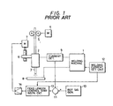
- Fig. 1 of the accompanying drawinqs is a block dia q ram showing a conventional feed length control device used in consumable electrode weldinq operations.
- reference numeral 1 designates a welding machine; 2, a torch for holding a wire electrode; and 4, a wire electrode feeding motor which rotates a pair of drive rollers 5 'to feed the wire electrode 3. Further in Fig.
- reference numeral 6 designates a torch moving mechanism for moving the torch 2 vertically; 7, a torch moving motor for operating the torch moving mechanism 6; 8, a metal base; 9, a current detector for detecting the welding current flowing between the wire electrode 3 and the metal base 8 supplied by the welding machine 1 and outputting a welding current detection signal; 10, a reference signal having a state determined according to the wire electrode feed length set in the welding operation; and 11, a comparator which compares the welding current detection signal outputted by the current detector 9 with the reference signal 10 to provide a deviation signal. Further in Fig.
- reference numeral 12 designates a welding current setting unit for setting the peak current value, base current value, peak current time and base current time of a welding current; 13, a feed length control start instruction circuit which, in response to the deviation signal from the comparator and an output signal of the welding current setting unit 12 establishes the feed control timing; and 14, a motor drive circuit for amplifying the output signal of the circuit 13 to drive the torch moving motor 7.
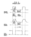
- feed length control device In the feed length control device thus constructed, while the wire electrode 3 is being fed by the wire electrode feeding motor 4, a welding current is caused to flow between the wire electrode 3 and the base 8 so that arcing occurs between the wire electrode 3 and the base 8 to achieve the welding operation. As shown in Fig. 2, feed length control is carried out while the welding current is in the base current period. While the welding current is in the peak current period, feed length control is not carried out, but the welding current is varied to control the weld penetration or the amount of deposition.
- the welding current set value is changed from a peak current set value to a base current set value instantaneously as shown in Fig. 2.
- the actual welding current set value cannot change from a peak current value to a base current value instantaneously. It has been found through measurement that it takes about 0.3 second for the welding current to change as described above.
- feed length control starts at the time instant when the welding current set value is changed from the peak current set value to the base current set value as shown in Fig. 2, in practice, feed length control is started before the welding current changes from the peak current value to the base current value. Further, the reference signal 10 for feed length control is made to coincide with the base current value. Therefore, disadvantageously the feed length is extremely short when feed length control starts.
- An object of the invention is to eliminate the above-described difficulties accompanying a conventional feed length control device used in a consumable electrode welding operation.
- a feed length control device for use in consumable electrode welding operations in which the start of feed length control is delayed for a predetermined period of time from the time instant when the welding current set value changes from the peak current set value to the base current set value; that is, feed length control is started when the actual welding current reaches the base current value. Accordingly, the feed length will not be extremely long when feed length control is started.
- a feed length control device used in consumable electrode welding operations comprises a delay circuit which delays the start of electrode wire feed length control for a predetermined period of time from the start of the base current set period.
- feed length control is carried out when the actual welding current reaches the base current value. Therefore, the feed length will not be excessively long at the start of feed length control, and the resultant weld will be satisfactory, having a deep weld penetration.
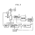
- Fig. 3 is a block diagram showing a welding machine constructed according to the invention.
- reference numerals 1 through 14 designate the same components as those in the above-described conventional device, and reference numeral 15 designates a delay circuit for delaying the start time of the feed length control signal.
- the start of feed length control is delayed by the delay circuit 15 for a predetermined period of time, for instance, about 0.4 second, from the time instant when the welding current set value is changed from the peak current set value to the base current set value; that is, feed length control is started when the actual welding current reaches the base current value. Therefore, the feed length will not be excessively long, and it is substantially constant at all times.
- the delay circuit 15 is added to the conventional device.
- a method of changing the reference signal 10 according to the actual welding current waveform may be employed, or a reverse bias voltage in the base current period of the welding current detection signal may be applied to make the welding current detecting signal constant for the base current period.
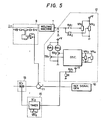
- Fig. 5 is a circuit diagram illustrating the circuits 9, 12, 13 and 15 in detail.
- the current detector 9 is implemented with Hall elements wherein a welding current I flowing therethrough generates a magnetic field in a direction vertical to the flow direction of the welding current due to Hall effect and a Hall voltage whose amplitude is proportional to the strength of the magnetic field is generated. This voltage signal is outputted as the output of the current detector after amplification.
- This type current detector is commercially available.
- the welding current setting unit 12 includes a base current instruction voltage adjustor (variable resistor) VR 1 , a peak current instruction voltage adjustor (variable resistor) VR 2 , a base current time adjustor (variable resistor) VR 3 and a peak current time adjustor (variable resistor) VR 4 .
- an oscillator OSC is provided to periodically turn ON and OFF transistors TR 1 and TR 2 alternately in accordance with set times adjusted by the time adjustors VR 3 and VR 4 .
- the transistor TR 1 is rendered conductive during the base current time
- the transistor TR 2 is rendered conductive during the peak current time.
- Relay circuits RA l and RA 2 are selectively actuated in response to the ON/OFF operation of the transistors TR 1 and TR 2 .
- a first terminal of each of the relay circuits RA 1 and RA 2 is coupled to the wiper terminals of VR 1 and VR 2 , to vary the base current value and the peak current value. The thus adjusted values are applied to the welding apparatus 1.
- the first terminal of the relay circuit RA l is further coupled to a power source +V and a resistor R.
- the junction point between the relay circuit RA l and the resistor R is coupled to the delay circuit 15.
- the feed length control start instruction circuit 13 is a gate circuit which functions to output the output of the comparator 11 to the motor drive circuit 14 at an appropriate time.
- An example of the circuit 13 is an analog switch of a type commercially available.
- the feed length control start instruction circuit 13 is a gate circuit which outputs the output of the comparator 11 to a motor drive circuit 14 at an appropriate time.
- An example of the circuit 13 is an analog switch of a type commercially available.
- the delay circuit 15 functions to delay the output timing of the base time output of the welding current setting unit 12 for the period of time set by a delay time setting time adjustor (variable resistor) VR 5 .
- the welding apparatus 1 When the base current and peak current instruction voltage, set by VR 1 to VR 4 in the welding current setting unit 12, are applied to the welding apparatus 1, the welding apparatus 1 operates to allow a welding current I to flow between the wire electrode 3 and the base metal 8.
- the welding current I is detected by the current detector 9 and compared with a reference signal from the circuit 10. This comparison result is amplified and then outputted as a difference signal.
- the output of the circuit 12 is directly connected to the circuit 13 to control the movement of the torch in both upward and downward directions during the base current period of the welding current.
- this apparatus is disadvantageous in that an undesired delay may occur between the output voltage signal of the circuit 12 and the actual welding current waveform signal, which is caused by the inertial force of the wire feeding motor. This undesired delay results in making it impossible to carry out a suitable control operation.
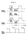
- the delay circuit 15 is provided to eliminate the difference of 0.3 sec. shown in Fig. 4.
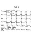
- the timing chart of Fig. 6 shows the ON/OFF operations of the transistors and relay circuits, the output of the timer 15, and the current instruction output signal.
- the start of feed length control is delayed for a predetermined period of time from the time instant when the welding current set value changes from the peak current set value to the base current set value; that is, feed length control is started only after the actual welding current reaches the base current value. Therefore, the feed length will never be excessively long, and therefore the resultant weld will be satisfactory, having a deep weld penetration.
Landscapes
- Engineering & Computer Science (AREA)
- Physics & Mathematics (AREA)
- Plasma & Fusion (AREA)
- Mechanical Engineering (AREA)
- Arc Welding Control (AREA)
Applications Claiming Priority (2)
| Application Number | Priority Date | Filing Date | Title |
|---|---|---|---|
| JP59219249A JPS6195775A (ja) | 1984-10-18 | 1984-10-18 | 消耗性電極溶接における突出長制御装置 |
| JP219249/84 | 1984-10-18 |
Publications (2)
| Publication Number | Publication Date |
|---|---|
| EP0178680A2 true EP0178680A2 (fr) | 1986-04-23 |
| EP0178680A3 EP0178680A3 (fr) | 1988-01-07 |
Family
ID=16732560
Family Applications (1)
| Application Number | Title | Priority Date | Filing Date |
|---|---|---|---|
| EP85113251A Withdrawn EP0178680A3 (fr) | 1984-10-18 | 1985-10-18 | Dispositif de contrôle de la longueur de dépassement pour des opérations de soudage à électrode consommable |
Country Status (3)
| Country | Link |
|---|---|
| US (1) | US4636610A (fr) |
| EP (1) | EP0178680A3 (fr) |
| JP (1) | JPS6195775A (fr) |
Cited By (1)
| Publication number | Priority date | Publication date | Assignee | Title |
|---|---|---|---|---|
| WO1999046078A1 (fr) * | 1998-03-10 | 1999-09-16 | Fronius Schweissmaschinen Produktion Gmbh & Co. Kg | Procede pour amorcer un arc entre une piece et une electrode fusible et dispositif permettant de mettre ledit procede en oeuvre |
Families Citing this family (5)
| Publication number | Priority date | Publication date | Assignee | Title |
|---|---|---|---|---|
| DE3545505C2 (de) * | 1985-12-20 | 1995-08-10 | Kuka Schweissanlagen & Roboter | Verfahren und Vorrichtung zum Aufsuchen und Verfolgen einer Kehlnaht beim Schutzgas-Lichtbogenschweißen |
| JPS63220979A (ja) * | 1987-03-06 | 1988-09-14 | Sankyo Seiki Mfg Co Ltd | Tig溶接方法 |
| CN1222395C (zh) * | 2003-08-19 | 2005-10-12 | 潘际銮 | 永磁履带自主全位置爬行式弧焊机器人的控制方法 |
| US7105776B2 (en) * | 2004-01-22 | 2006-09-12 | Illinois Tool Works Inc | Method and apparatus for welding with start control |
| US11383318B2 (en) | 2018-02-02 | 2022-07-12 | Liburdi Engineering Limited | Filler wire position control |
Family Cites Families (8)
| Publication number | Priority date | Publication date | Assignee | Title |
|---|---|---|---|---|
| FR1368492A (fr) * | 1963-09-03 | 1964-07-31 | Union Carbide Corp | Réglage du rapprochement de l'électrode dans un poste de soudage à l'arc |
| JPS53129141A (en) * | 1977-04-19 | 1978-11-10 | Matsushita Electric Ind Co Ltd | Controller for welding arc voltage or arc length |
| JPS5415449A (en) * | 1977-07-06 | 1979-02-05 | Osaka Transformer Co Ltd | Method and apparatus for nonconsumable electrode arc welding |
| JPS5719168A (en) * | 1980-07-08 | 1982-02-01 | Mitsubishi Electric Corp | Pulse arc welding machine |
| JPS5762865A (en) * | 1980-09-22 | 1982-04-16 | Mitsubishi Electric Corp | Pulse arc welding machine |
| JPS58179571A (ja) * | 1982-04-14 | 1983-10-20 | Mitsubishi Electric Corp | パルスア−ク溶接機 |
| DE3219726C2 (de) * | 1982-05-26 | 1992-07-23 | Universal Tiefpunkt Schweißmaterial GmbH & Co, 7812 Bad Krozingen | Vorrichtung zum Lichtbogenschweißen mit einer nachgeführten abschmelzenden Elektrode |
| JPS5985374A (ja) * | 1982-11-09 | 1984-05-17 | Mitsubishi Heavy Ind Ltd | 溶接線自動倣い方法 |
-
1984
- 1984-10-18 JP JP59219249A patent/JPS6195775A/ja active Pending
-
1985
- 1985-10-18 EP EP85113251A patent/EP0178680A3/fr not_active Withdrawn
- 1985-10-18 US US06/789,257 patent/US4636610A/en not_active Expired - Fee Related
Cited By (1)
| Publication number | Priority date | Publication date | Assignee | Title |
|---|---|---|---|---|
| WO1999046078A1 (fr) * | 1998-03-10 | 1999-09-16 | Fronius Schweissmaschinen Produktion Gmbh & Co. Kg | Procede pour amorcer un arc entre une piece et une electrode fusible et dispositif permettant de mettre ledit procede en oeuvre |
Also Published As
| Publication number | Publication date |
|---|---|
| US4636610A (en) | 1987-01-13 |
| JPS6195775A (ja) | 1986-05-14 |
| EP0178680A3 (fr) | 1988-01-07 |
Similar Documents
| Publication | Publication Date | Title |
|---|---|---|
| KR840002190B1 (ko) | 펄스아아크 용접장치 | |
| US3731049A (en) | Control apparatus for short-circuit arc welding | |
| US3551637A (en) | Magnetic control of a welding arc | |
| JP2809683B2 (ja) | パルスアーク溶接機 | |
| CA1187562A (fr) | Dispositif et methode de soudage | |
| US4647754A (en) | Consumable electrode type pulse arc welding machine | |
| EP0178680A2 (fr) | Dispositif de contrôle de la longueur de dépassement pour des opérations de soudage à électrode consommable | |
| US4476376A (en) | Direct-current arc welding machine having current control for preventing arc extinction following short circuits | |
| JPS61203222A (ja) | 放電加工用工具電極の消耗率を測定する方法及び装置 | |
| EP0007968A1 (fr) | Ameliorations aux methodes et appareils d'usinage par electroerosion. | |
| SU1496945A1 (ru) | Способ определени вылета электрода и устройство дл его осуществлени | |
| SU693346A1 (ru) | Система управлени скоростью вращени электродвигател механизма подачи электродной проволоки | |
| KR890001682A (ko) | 비이드 제어방법 | |
| JPS57202974A (en) | Controlling method for arc welding machine using consumable electrode | |
| JPS57171574A (en) | Arc welding machine | |
| JPS6344490B2 (fr) | ||
| JPS5762865A (en) | Pulse arc welding machine | |
| JPS57130771A (en) | Pulse arc welding device | |
| KR880001188B1 (ko) | 글로브럴 용접기 및 쇼티드 아아크 용접기를 사용하는 아아크센싱 시스템에서의 전류 검출 신호처리회로 | |
| SU463524A1 (ru) | Устройство дл автоматического управлени процессами сварки-пайки | |
| SU759288A1 (ru) | Автоматический регулятор ме.жэлектродного . промежутка' ........ ·'« 1 | |
| JPS57168775A (en) | Short circuit transfer arc welding machine | |
| SU1488152A1 (ru) | Устройство дл слежени за рассто нием от горелки до издели | |
| JPH0661662B2 (ja) | ワイヤカツト放電加工装置 | |
| SU1171247A1 (ru) | Устройство дл регулировани напр жени импульсной дуги |
Legal Events
| Date | Code | Title | Description |
|---|---|---|---|
| PUAI | Public reference made under article 153(3) epc to a published international application that has entered the european phase |
Free format text: ORIGINAL CODE: 0009012 |
|
| AK | Designated contracting states |
Kind code of ref document: A2 Designated state(s): DE FR GB |
|
| PUAL | Search report despatched |
Free format text: ORIGINAL CODE: 0009013 |
|
| AK | Designated contracting states |
Kind code of ref document: A3 Designated state(s): DE FR GB |
|
| 17P | Request for examination filed |
Effective date: 19880202 |
|
| 17Q | First examination report despatched |
Effective date: 19880923 |
|
| STAA | Information on the status of an ep patent application or granted ep patent |
Free format text: STATUS: THE APPLICATION IS DEEMED TO BE WITHDRAWN |
|
| 18D | Application deemed to be withdrawn |
Effective date: 19891205 |
|
| RIN1 | Information on inventor provided before grant (corrected) |
Inventor name: NAKANE, RYUJIC/O MITSUBISHI DENKI K.K. Inventor name: SUWAHARA, HIROSHIC/O MITSUBISHI DENKI K.K. Inventor name: KAMO, KAZUHIKOKOBE SHIPYARD ENGINE WORKS |